Hai bisogno delle specifiche complete?
Scarica il nostro Catalogo prodotti 2025 per disegni dettagliati e parametri tecnici di tutti i componenti dei quadri elettrici.
Richiedi il catalogo
Scarica il nostro Catalogo prodotti 2025 per disegni dettagliati e parametri tecnici di tutti i componenti dei quadri elettrici.
Richiedi il catalogo Scarica il nostro Catalogo prodotti 2025 per disegni dettagliati e parametri tecnici di tutti i componenti dei quadri elettrici.
Richiedi il catalogo
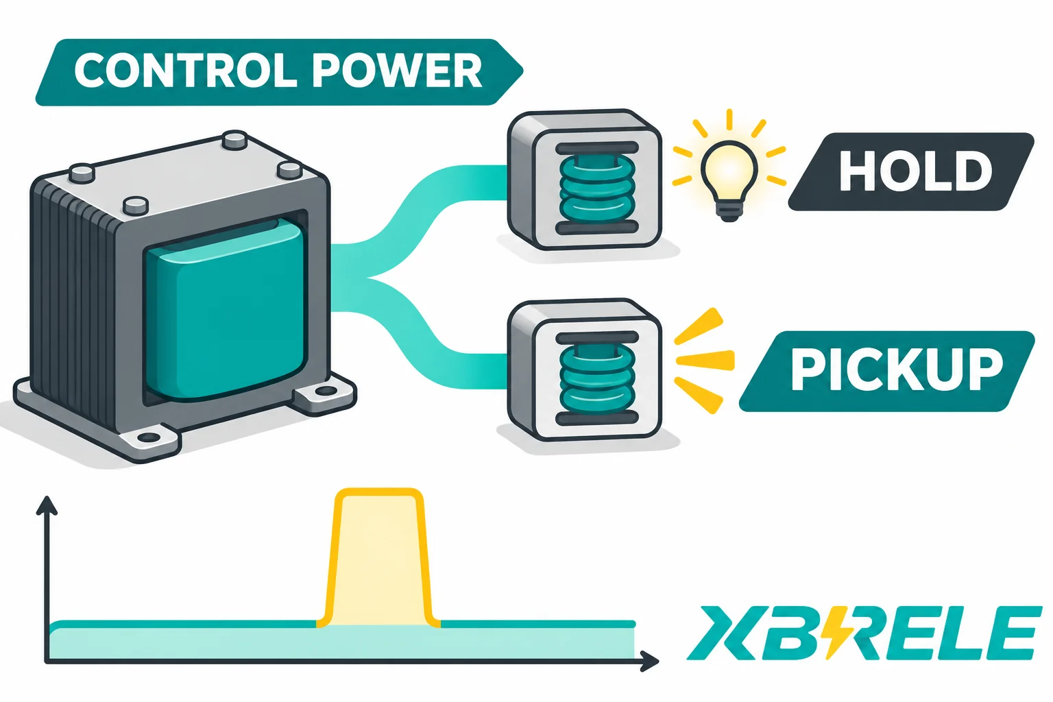
Size MV contactor control power around sealed VA, simultaneous pickup events, regulation and coil-terminal voltage, with a worked load-event worksheet.
A control power transformer feeding medium-voltage contactor coils has to pass two different tests, and only one of them is about heat. The continuous test is thermal: every coil that stays closed, plus relays, lamps and electronic modules, draws current for hours, and the transformer, its enclosure and its upstream protection must tolerate the resulting losses and temperature rise. The transient test is electrical: with a conventional AC coil, at the instant one or more contactors are commanded to close, the armatures are still open, coil impedance is low and demand rises above the sealed burden. The resulting voltage depression depends on the coil and source; rectified, electronic and direct DC drives require their own input data. If that sag takes the voltage at the coil terminals below what the coil needs to pull in, the contactor chatters, hesitates or fails to close. Getting the selection right means satisfying both tests at the actual coil terminals, for the worst credible combination of loads, rather than applying one oversizing factor to the largest coil.
A control power transformer is a small dry-type transformer whose job is to create a control-voltage bus from the primary source available in the switchgear. Its secondary supplies the contactor coils, auxiliary relays, timers, indicating lamps, position indicators, small motors such as spring-charging or shutter motors where fitted, and increasingly the electronic modules that supervise and drive the coils. Everything on that secondary shares one source impedance, which is the key fact behind the whole selection problem: one coil closing affects the voltage seen by every other device on the bus.
Motor kilowatts and the main contactor ampere rating do not give the coil burden. The main circuit and the control circuit are electrically separate. The coil is an electromagnet sized for the contactor mechanism, and its burden is set by its winding, its armature geometry and, for electronic drives, by the driver design. Two contactors with very different main-circuit ratings can use the same coil; a larger contactor may use a larger coil, but the relationship is not derivable from the ampere rating. Reasoning from 400 A or 630 A to a coil VA figure is guesswork dressed as an estimate.
When an AC contactor is fully closed, the armature is seated, the air gap in the magnetic circuit is minimal, the inductance is high and the current falls to the sealed value. That sealed current produces copper loss in the coil and in the transformer winding, and it flows for as long as the contactor stays closed. The continuous check is therefore a heating check: sum the sealed VA of every held coil, add the other continuous loads, apply the ambient and enclosure conditions, and compare the total with the transformer’s continuous capability.
Pickup burden is set by the open magnetic circuit. Before the contactor closes, the armature is held apart by the return spring and the air gap is large. A large air gap means low inductance, and low inductance at the same applied voltage means a much higher current. That current exists only until the armature seats — tens to a few hundred milliseconds — and then collapses to the sealed value. The immediate pickup check is voltage regulation: can the source deliver the burst while keeping the secondary voltage high enough to close the contactor? Repeated or prolonged pickups also contribute to heating and must remain within the transformer and coil duty limits.
Because the two currents differ in magnitude and in duration, they answer different questions and cannot be collapsed into one number. A transformer that carries the continuous load comfortably may still dip too far during a multi-coil pickup; a transformer large enough to hold voltage during that pickup may be far larger than the continuous duty requires.
Electronic and DC coil drives need their own data. A coil with a built-in rectifier, an economizer circuit or a full electronic drive can present a different input burden from a simple AC coil. Its current may be non-sinusoidal or deliberately limited after pull-in, and its pickup behaviour depends on the complete input circuit rather than on the air gap alone. Multiplying an AC coil’s sealed VA by a generic inrush factor is not a valid substitute for the drive’s published input data. The winding VA inside the contactor and the input VA at the transformer are not the same quantity.
No transformer can be selected before every load on the secondary has been identified in both of its states. The inventory is a table, one row per device type, and each row must carry enough data to support both the thermal check and the event check.
The following reduced inventory uses assumed values for the worked example below; it is not a coil datasheet or a selected equipment specification. A project inventory should also record pickup duration, the exact input voltage and frequency, and the manufacturer document for every entry.
| Load | Quantità | Pickup input burden, assumed | Held input burden, assumed | Coincidence to assess |
|---|---|---|---|---|
| Contactor A | 1 | 180 VA | 20 VA | Separate and simultaneous pickup with B |
| Contactor B | 1 | 120 VA | 15 VA | Separate and simultaneous pickup with A |
| Other continuous loads, aggregate | 1 | 40 VA throughout the event | 40 VA | Present in every event |
Two unit problems appear immediately in that table. The first is VA versus W. Volt-amperes measure the product of RMS voltage and RMS current and include the reactive component; watts measure real power only. A sealed AC coil has a power factor well below unity, so its watt figure and its VA figure are not interchangeable, and the current it actually carries drives winding I²R losses, while core and other losses also contribute to heating. VA therefore matters alongside the load waveform and operating conditions. Where a device is specified in watts only — lamps, heaters, some electronic supplies — convert with the device’s own power factor or obtain the VA figure from the manufacturer instead of guessing.
The second is AC versus DC or rectified input. A rectifier or electronic driver can change the waveform and power factor seen by the transformer; the result depends on the input circuit, smoothing and load. Direct DC-coil current alone does not describe that AC input burden. The correct entry in the table is the manufacturer’s stated input VA or input current at the stated supply, defined the same way the transformer chart expects. If the coil is fed from a DC bus with its own power supply, the inventory must describe the DC supply input, not the coil output.
Missing data is a design gap, not a blank to fill with a factor. Where pickup VA or pickup duration is unknown, the coil or contactor manufacturer is the only useful source; a value inferred from the main-circuit rating or borrowed from another contactor family is an assumption that has to be written down and accepted as one. Coil duty is model-specific: two coils with the same nominal voltage may differ in sealed VA, pickup VA, permissible voltage window and duty cycle.
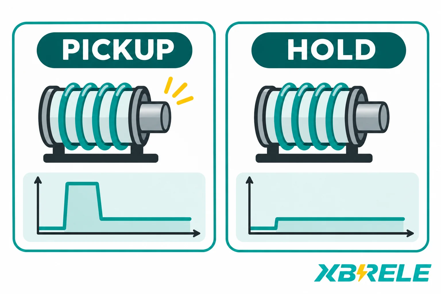
The continuous total and the worst event total are different numbers and serve different purposes. The continuous total sets the minimum thermal size; the event total, combined with the transformer’s own regulation data, decides whether the coils will actually close.
Take a switchgear section with two vacuum contactors, A and B, plus an auxiliary relay bank, lamps and a monitoring module. Using the explicitly assumed inventory above — A pickup 180 VA with 20 VA held, B pickup 120 VA with 15 VA held, and an aggregate 40 VA of other continuous load — the arithmetic is straightforward.
| Event | Loads counted | Total burden |
|---|---|---|
| All contactors closed, steady state | A held 20 + B held 15 + other 40 | 75 VA |
| A picks up while B holds | A pickup 180 + B held 15 + other 40 | 235 VA |
| B picks up while A holds | B pickup 120 + A held 20 + other 40 | 180 VA |
| A and B pick up in the same event | A pickup 180 + B pickup 120 + other 40 | 340 VA |
These figures are design assumptions for illustrating the method. They are not catalogue values for any particular coil, and a real inventory will produce different numbers.
The rule that prevents error is simple: a coil is counted once, in the state it occupies during that event. A coil that is picking up is entered at its pickup burden and not at pickup plus held. A coil that is already closed is entered at its held burden. Continuous loads that never change state are entered once in every event. Applied consistently, this rule avoids the common double count in which the largest coil’s inrush is added on top of a total that already includes that coil’s sealed burden.
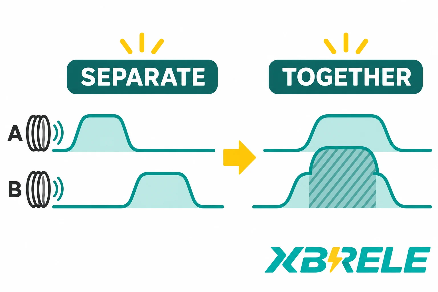
The arithmetic total is not a transformer rating. A 340 VA event figure does not mean a 340 VA transformer is adequate, and it does not mean a 340 VA transformer is inadequate. What the figure does is define the burden that a candidate transformer’s regulation data must be consulted with: a given transformer produces a particular secondary voltage when that burden is drawn at the event’s power factor, from the primary voltage that actually exists. Selecting the transformer means reading that relationship, not matching the arithmetic total to a nameplate.
The highest-total event is also not always the one an operator would predict. Coils that are normally closed one at a time can be commanded together after a supply dip, after a control-bus transfer, after a protection trip and reset, or when an operator closes several feeders during commissioning. A restart event in which every contactor that dropped out re-energizes at once is often the worst credible case, and it can be substantially larger than any planned sequence. A manufacturer’s largest-inrush shortcut holds only when the real operating event is consistent with the assumption behind it; it does not demonstrate that multiple commanded coils cannot start together.
Regulation is the drop in secondary voltage between no load and the load in question, expressed as a percentage of nominal, and for a small transformer feeding a low-power-factor burst it can be large. Four quantities decide whether the coils will close.
The transformer’s own inrush regulation data. Schneider Electric’s control-transformer selection guide separates continuous burden from the simultaneous pickup event, then checks the candidate against its own regulation table. The table belongs to that transformer family; it is not a general MV contactor rating.
Manufacturers publish regulation curves for each transformer family: secondary voltage drop as a function of inrush burden, at a stated inrush power factor, for each size, each primary voltage and each output frequency. A candidate is checked against its own chart, and when that chart shows the secondary voltage collapsing under the event burden, the correct move is to step to a larger size and read that chart in turn. These charts are revision-controlled documents; the revision, the size column, the primary voltage column and the frequency must be recorded, because a different chart gives a different answer.
The transient power factor of the event. Pickup current is dominated by the magnetizing branch of the coil, so the event power factor is low compared with the steady-state load. Regulation curves are drawn for a specified inrush power factor, and the drop depends on it: the voltage change depends on the load power factor and the transformer impedance. For a given transformer, the manufacturer chart defines which conditions its inrush capacity covers. A chart used outside its stated power-factor conditions can misrepresent the dip; the direction and size of the error depend on the transformer impedance and actual load.
The minimum primary voltage. The regulation curve gives a drop as a proportion, and that proportion is applied to the voltage actually present at the primary. If the primary is already at the bottom of its permitted band — a depressed bus during a motor start elsewhere in the plant, or a long control supply run — the secondary during the event is lower than in the chart’s nominal-primary case. The check must use the minimum credible primary voltage, not nominal.
The downstream path. Transformer secondary terminals are not coil terminals. Cable resistance and reactance, fuse and breaker contacts, control contacts, terminal blocks and the return conductor all consume voltage while the burst current flows. A long run to a remote starter enclosure can add a drop comparable to the transformer’s own. On DC or rectified coil paths, the rectifier bridge contributes a roughly fixed forward drop that becomes significant at low voltages. The distribution path has to be calculated separately and subtracted, so that the acceptance decision is made where the coil actually sits.
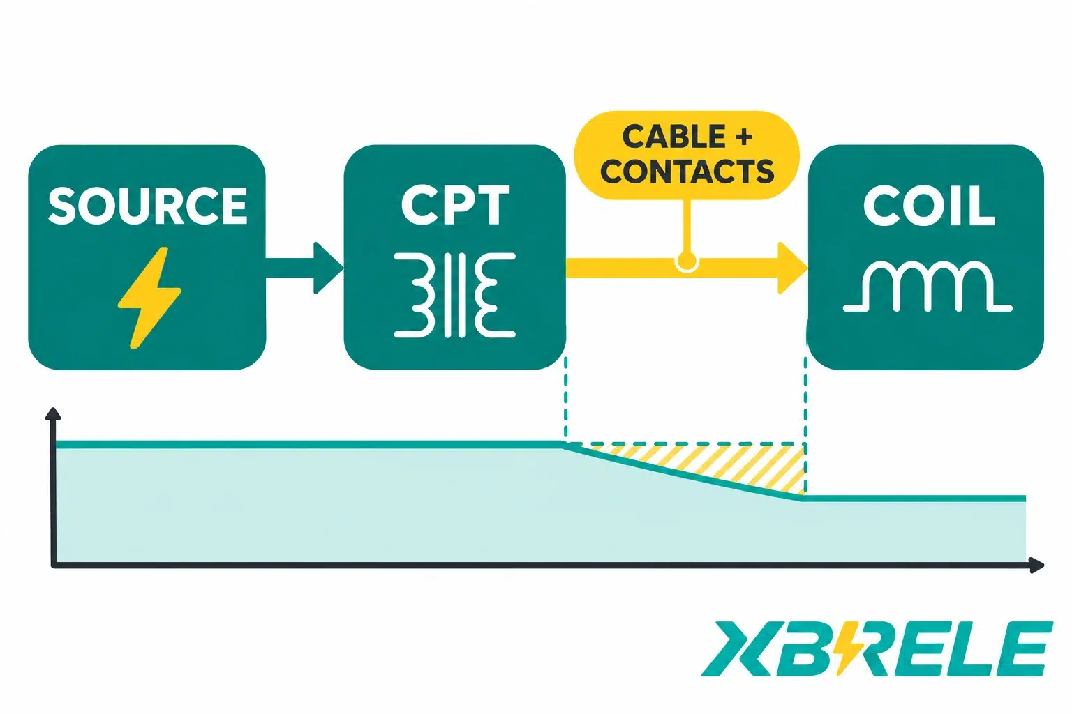
Only then does the coil’s own acceptance criterion apply. An AC contactor coil has a minimum pickup voltage — below it the contactor will not close reliably — and a specified holding or dropout characteristic for the closed state. Those characteristics describe different operating conditions. An electronic drive specifies an input voltage window with its own minimum and maximum, and may specify a minimum source capability or a maximum supply impedance. Those limits belong to the specific coil and driver, and they are not transferable between models or between voltage classes. Low-voltage control examples and simple percentage rules should not be carried over to every medium-voltage contactor as though they were universal; the required figure is the one in the documentation for the coil being used.
A selection is complete when the worksheet below is filled with evidence rather than intentions. Each line corresponds to a decision that can change the answer.
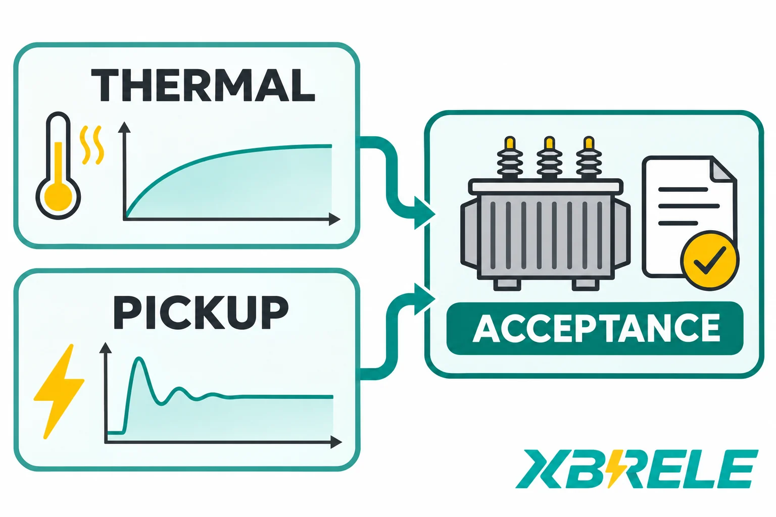
Two design choices sit behind line 3. If the electrical design permits simultaneous restart, the transformer must be accepted for the simultaneous event, and the assessment above does that directly. If the design instead relies on a staged restart, with interlocks holding some contactors off until others have sealed, the design depends on that sequencing, so loss of staging must be evaluated: relay logic with a single failed auxiliary contact, a loose terminal or a firmware default can silently collapse the staging and recreate the simultaneous event. A written operating procedure is weaker evidence than hardened logic, and either way the assumption belongs on the drawing rather than in someone’s memory.
Upsizing is not a cure for a control circuit that is wrong in other ways. A larger transformer does not fix corroded or loose coil terminals, a coil of the wrong voltage or frequency, a supply frequency that does not match the transformer or coil rating (a transformer does not convert frequency), a binding armature, a worn shading ring or contamination in the magnet path. Those faults produce the same symptom — a contactor that will not close or will not hold — and they persist after the transformer has been changed.
The light-load condition deserves a line of its own, because the check is usually written only at the bottom end. At light load the secondary voltage rises above nominal, by the same regulation mechanism running in reverse, and a primary sitting at the top of its band pushes it higher still. Coils, economizer circuits, electronic drives, lamps and small power supplies all have maximum voltage limits, and a control bus designed only against the worst dip can exceed them in a lightly loaded condition. Both ends of the operating range belong in the worksheet.
A contactor supplier or switchgear builder can only confirm a coil-driven design when the inquiry contains the actual operating conditions. A useful package contains:
XBRELE’s vacuum contactor range — the CKG, JCZ and LCZ series together with the low-voltage and solid series — is catalogued at the vacuum contactor family page; coil and control-supply documentation for a specific model and configuration is requested per project rather than assumed from the family listing. Send the load inventory and the event table to the contact page together with the primary supply data, so the coil characteristics and the control supply are reviewed against the same event definition.
Because the coil is not in the main circuit. The main contacts carry the motor current and are sized for it; the coil is a separate electromagnet that operates the mechanism, and its burden is fixed by its own winding, magnetic circuit and driver. A 400 A and a 630 A contactor can share a coil, and a larger contactor may use a larger coil, so the ampere rating gives no usable conversion to VA. The coil’s pickup and sealed VA come from its documentation, and that is the only entry that belongs in the continuous and event arithmetic.
Only if the real operating event is one coil at a time. If two or more coils can be commanded together — after a supply dip, a control-bus transfer, a protection reset or manual closing during commissioning — their pickup burdens overlap and the combined event exceeds the largest single coil. The overlap case also carries every coil already held plus the other continuous load. Size against the largest credible combination, not the largest individual device.
VA is the product of RMS voltage and RMS current and includes the reactive component; W is real power. A coil’s sealed burden has a power factor well below unity, so its W and its VA are different numbers, and the winding I²R losses depend on the current the transformer carries, with core and other losses also contributing. Lamps, heaters and electronic supplies are often specified in W, and those figures must be converted using the device’s own power factor or replaced with the manufacturer’s VA figure. Mixing the two units in one column produces a total that is neither.
No. A rectifier or electronic driver can change the input current waveform and may limit or shape current after pull-in. A direct DC coil also has different transient behaviour from a simple AC coil. Pickup and held input burdens are design characteristics, not a universal multiple of an AC coil’s values. Input VA at the transformer is also not the same as winding VA inside the contactor. Use the drive’s published input data, including the supply conditions under which it was defined, and enter it at the transformer in the units the regulation chart expects.
It can, but only when the staging is enforced by validated interlocks rather than by procedure alone. A simultaneous restart is often the worst credible event precisely because it arrives when normal sequencing is unavailable. If the design relies on holding some contactors off until others have sealed, the design review must evaluate what happens if staging is lost through a stuck auxiliary contact, loose terminal or default parameter. The event table and drawings should record that dependency and any required response. Whether staging also performs a safety function depends on the application and its requirements.
It can be. The same regulation that produces the pickup dip produces a rise at light load, and a primary at the top of its tolerance band adds to it. Coils, economizer circuits, electronic drives and small power supplies have maximum voltage limits as well as minimums, so the worksheet should check the lightly loaded condition as well as the worst dip. A control bus verified only at the low end of its range is only half verified.