Hai bisogno delle specifiche complete?
Scarica il nostro Catalogo prodotti 2025 per disegni dettagliati e parametri tecnici di tutti i componenti dei quadri elettrici.
Richiedi il catalogoScarica il nostro Catalogo prodotti 2025 per disegni dettagliati e parametri tecnici di tutti i componenti dei quadri elettrici.
Richiedi il catalogoScarica il nostro Catalogo prodotti 2025 per disegni dettagliati e parametri tecnici di tutti i componenti dei quadri elettrici.
Richiedi il catalogo
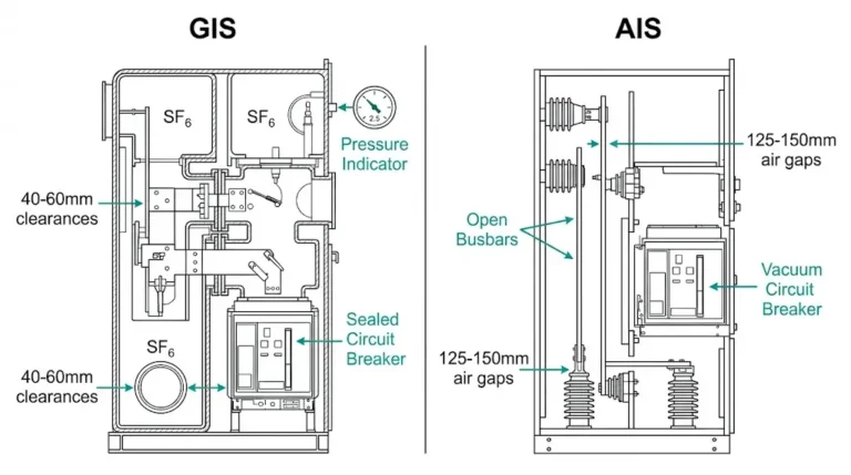
Un interruttore sottovuoto da 12 kV è arrivato in un cementificio sulle Ande, installato a 2.800 metri di altezza. Sei mesi dopo, si è guastato durante una commutazione di routine, non per un difetto di fabbricazione, ma per un flashover su superfici isolanti che si erano comportate perfettamente durante i test di fabbrica a livello del mare.
La causa principale: un livello di impulso di base inadeguato per le sollecitazioni combinate di alta quota e polvere di cemento. Il BIL standard da 75 kV, sufficiente a 1.000 metri in aria pulita, non poteva sopportare sovratensioni transitorie quando la densità dell'aria scendeva a 30% e l'inquinamento ricopriva ogni superficie esposta.
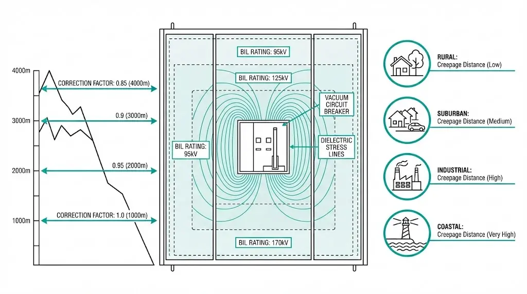
Il coordinamento dell'isolamento previene esattamente questa modalità di guasto. Il coordinamento dell'isolamento previene proprio questa modalità di guasto, adeguando la rigidità dielettrica dell'apparecchiatura alle reali sollecitazioni di tensione, tenendo conto del luogo in cui l'apparecchiatura opera, non solo della tensione che trasporta. Il BIL quantifica la capacità di resistenza alle sovratensioni transitorie, espressa in kilovolt di picco per una forma d'onda standardizzata di impulso di fulmine.
Tre fattori dominano la selezione dei BIL di media tensione: l'altitudine (riduzione della densità dell'aria), la gravità dell'inquinamento (contaminazione superficiale) e le caratteristiche del sistema di cavi (adattamento dell'impedenza di sovratensione). Questa guida fornisce metodi pratici di selezione per ciascuno di essi, con calcoli e tabelle decisionali basati sulle norme IEC che gli ingegneri possono applicare direttamente alle specifiche di approvvigionamento.
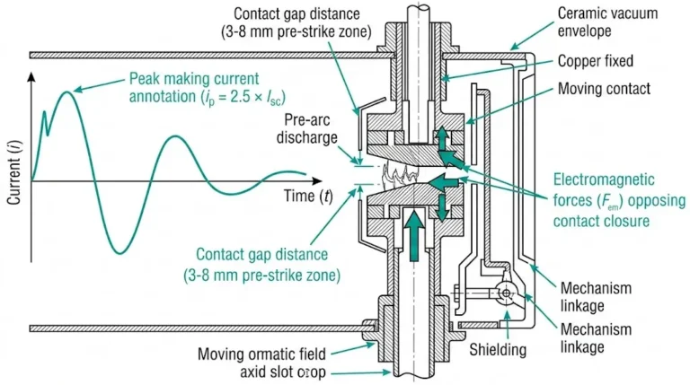
Per una comprensione fondamentale di principi di funzionamento degli interruttori in vuoto, La risorsa collegata copre i meccanismi di estinzione dell'arco e la progettazione dei contatti che influenzano i requisiti di isolamento.
Il Basic Impulse Level definisce la grandezza della tensione di picco che le apparecchiature elettriche devono sopportare durante gli eventi di sovratensione transitoria, in particolare i fulmini e le sovratensioni di commutazione. Per i sistemi a media tensione tra 3,6 kV e 36 kV, i valori BIL variano in genere da 40 kV a 170 kV, il che rappresenta un rapporto da 5:1 a 6:1 tra la resistenza agli impulsi e la tensione operativa nominale.
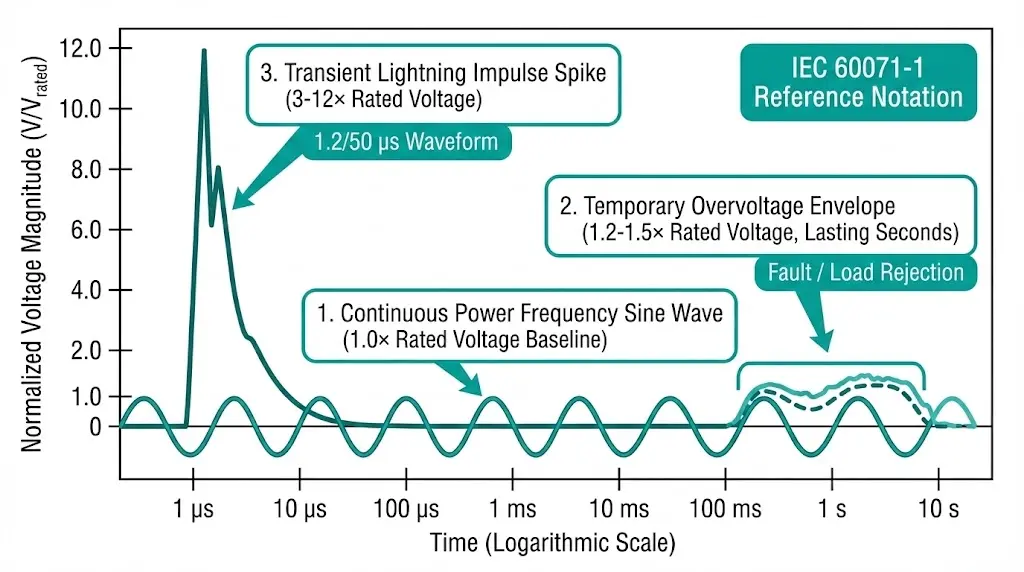
La fisica si concentra sulla relazione tensione-tempo durante gli eventi impulsivi. Un impulso standard di fulmine raggiunge il picco in 1,2 microsecondi e decade a 50% in 50 microsecondi (la forma d'onda 1,2/50 μs definita dalla norma IEC 60060-1). Questo rapido picco di tensione sollecita l'isolamento in modo diverso rispetto alla tensione continua a frequenza di alimentazione.
Tre categorie di sollecitazioni di tensione richiedono un coordinamento:
| Tipo di stress | Durata | Magnitudo tipica | Fonte |
|---|---|---|---|
| Frequenza di alimentazione | Continuo | 1,0 × tensione nominale | Funzionamento normale |
| Sovratensione temporanea | Da secondi a minuti | 1,2-1,5 × tensione nominale | Eliminazione dei guasti, rifiuto del carico |
| Sovratensione transitoria | Microsecondi | 3-12 × tensione nominale | Fulmini, commutazione |
Secondo la norma IEC 60071-1 (Coordinamento dell'isolamento-Parte 1: Definizioni, principi e regole), i valori BIL standard seguono una serie preferenziale. Per i sistemi Um = 36 kV, il BIL standard è di 170 kV, mentre i sistemi Um = 12 kV richiedono tipicamente valori di BIL di 75 kV o 95 kV a seconda della configurazione della messa a terra del neutro e della gravità della sovratensione prevista.
La capacità di resistenza dielettrica dipende da tre fattori interconnessi: la resistenza alla rottura del materiale isolante (in genere 20-40 kV/mm per i cavi XLPE), la configurazione geometrica che determina la distribuzione del campo elettrico e le condizioni ambientali, compresa la pressione atmosferica.
Valori nominali standard BIL per apparecchiature a media tensione:
| Tensione nominale (kV) | Opzioni BIL standard (kV di picco) |
|---|---|
| 3.6 | 20, 40 |
| 7.2 | 40, 60 |
| 12 | 60, 75, 95 |
| 17.5 | 75, 95 |
| 24 | 95, 125, 145 |
| 36 | 145, 170 |
La scelta tra le opzioni dipende dal metodo di messa a terra del sistema, dalla frequenza di esposizione ai fulmini e da fattori ambientali critici che riducono la rigidità dielettrica effettiva.
La densità dell'aria diminuisce con l'altitudine, riducendo proporzionalmente la rigidità dielettrica. Al livello del mare (1.013 hPa), l'aria standard offre una capacità di isolamento di base. Con l'aumentare dell'altitudine, le molecole si allontanano e la tensione di rottura diminuisce. Un'apparecchiatura con un valore nominale di 75 kV BIL al livello del mare può effettivamente fornire solo 60 kV BIL a 3.000 metri senza correzioni.
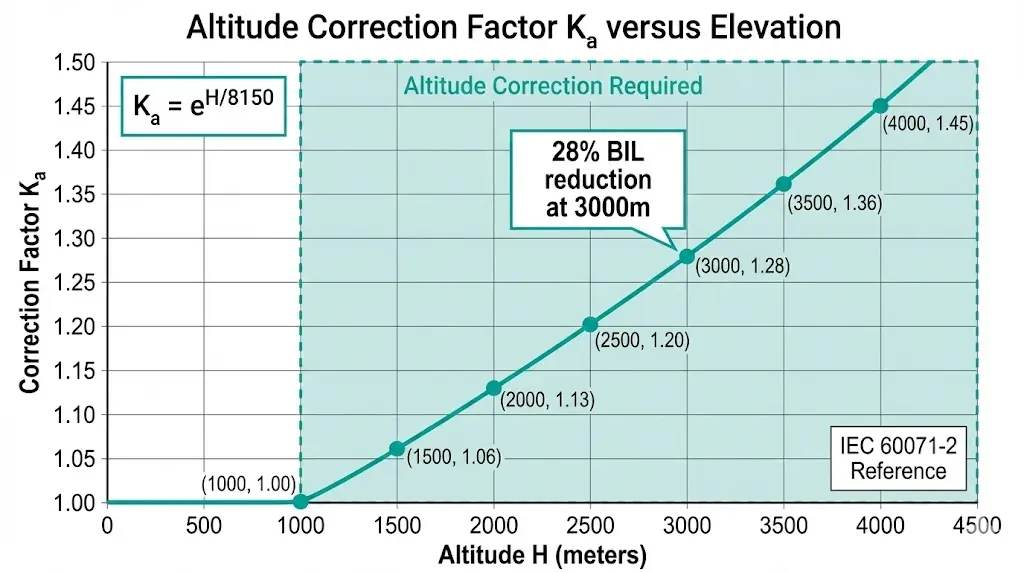
La correzione diventa obbligatoria al di sopra dei 1.000 metri secondo la norma IEC 60071-2. La formula:
K_a = e^(H/8150)
Dove K_a equivale al fattore di correzione dell'altitudine e H rappresenta l'altitudine in metri.
Fattori di correzione dell'altitudine precalcolati:
| Altitudine (m) | Fattore di correzione K_a | Riduzione effettiva del BIL |
|---|---|---|
| 1,000 | 1,00 (riferimento) | 0% |
| 1,500 | 1.06 | 6% |
| 2,000 | 1.13 | 13% |
| 2,500 | 1.20 | 20% |
| 3,000 | 1.28 | 28% |
| 3,500 | 1.36 | 36% |
| 4,000 | 1.45 | 45% |
Applicazione pratica: Un VCB da 12 kV destinato a un sito di 2.500 m richiede un BIL di almeno 75 × 1,20 = 90 kV. Selezionare il rating standard successivo: 95 kV BIL.
Per la compensazione dell'altitudine esistono due opzioni di implementazione. In primo luogo, specificare apparecchiature di classe BIL più elevata: 95 kV invece di 75 kV a parità di tensione nominale. In secondo luogo, richiedere distanze di dispersione e di sicurezza più ampie e proporzionalmente maggiori. La maggior parte produttori di interruttori automatici sottovuoto Offrono varianti con altitudine. Specificare l'altitudine di installazione nei documenti RFQ: il riadattamento costa molto di più di una corretta specifica iniziale.
[Expert Insight: Selezione dell'altitudine]
- I siti al di sopra dei 2.000 m dovrebbero essere assegnati di default alla classe BIL immediatamente superiore, indipendentemente dai risultati dei calcoli.
- Gli ambienti secchi, a bassa umidità e ad alta quota, registrano un più rapido recupero della tensione dopo le scariche parziali
- Gli effetti combinati dell'altitudine e dell'inquinamento si sommano: applicare entrambe le correzioni in sequenza.
- Richiedere i certificati di prova in altitudine del produttore per le installazioni al di sopra dei 3.000 m
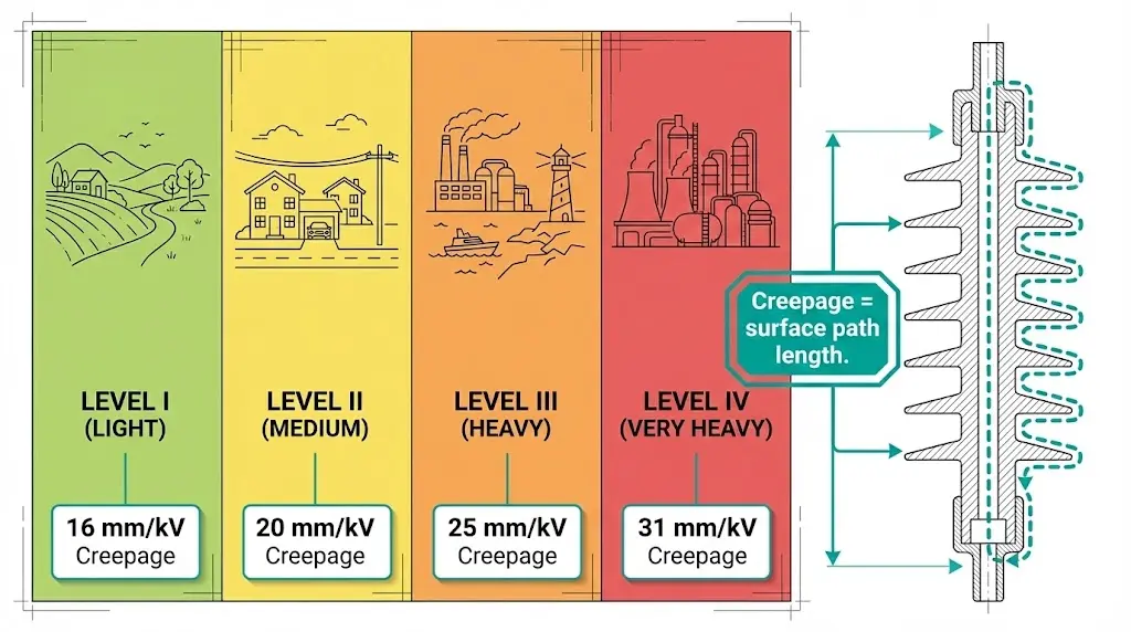
La contaminazione superficiale - spruzzi di sale, polvere di cemento, particolato industriale, prodotti chimici agricoli - crea percorsi conduttivi se combinata con l'umidità. La norma IEC 60815 definisce quattro livelli di gravità dell'inquinamento in base all'esposizione ambientale:
| Livello di inquinamento | Descrizione | Ambienti tipici |
|---|---|---|
| I - Luce | Inquinamento industriale minimo, assenza di sale | Aree rurali, bassa densità di traffico |
| II - Medio | Moderata esposizione industriale o al traffico | Zone suburbane, industria leggera |
| III - Pesante | Densa attività industriale, costa 1-10 km | Produzione pesante, vicino alla costa |
| IV - Molto pesante | Polvere conduttiva, nebbia salina diretta, sostanze chimiche | Cementifici, impianti costieri, lavorazione di prodotti chimici |
La distanza di dispersione, ovvero la lunghezza del percorso superficiale tra le parti in tensione e il suolo, deve aumentare con la gravità dell'inquinamento:
| Livello di inquinamento | Minimo scorrimento (mm/kV) |
|---|---|
| I - Luce | 16 |
| II - Medio | 20 |
| III - Pesante | 25 |
| IV - Molto pesante | 31 |
Esempio di calcolo: Le apparecchiature a 12 kV in ambiente di livello III richiedono uno scorrimento minimo di (12 ÷ √3) × 25 = 173 mm.
Le apparecchiature interne in locali di commutazione adeguatamente sigillati e a clima controllato sono in genere classificate per il livello di inquinamento I o II. Tuttavia, l'esperienza sul campo rivela che gli spazi interni scarsamente ventilati, in particolare nelle miniere e nelle cementerie, accumulano contaminazione nell'arco di 5-10 anni, creando percorsi di tracciamento in superficie. Valutare la qualità effettiva dell'aria piuttosto che dare per scontato che gli ambienti interni siano automaticamente puliti.
Per Selezione di VCB per esterni e per interni, La determinazione del livello di inquinamento influisce in modo significativo sia sul costo iniziale dell'apparecchiatura che sull'affidabilità a lungo termine.
I siti ad alta quota coincidono spesso con un grave inquinamento: operazioni minerarie a 3.500 m, cementifici nelle valli di montagna, impianti industriali remoti lontani dalle infrastrutture di rete. Entrambi i fattori di declassamento si sommano.
Metodo di applicazione sequenziale:
Esempio funzionante: VCB da 24 kV all'aperto a 3.500 m di altezza in un cementificio (livello di inquinamento IV):
Matrice decisionale di selezione combinata:
| Condizioni del sito | Azione raccomandata |
|---|---|
| ≤1.000 m, Inquinamento I-II | BIL standard, strisciamento standard |
| 1.000-2.000 m, Inquinamento I-II | Prossima classe BIL superiore |
| >2.000 m, qualsiasi inquinamento | Calcolare il K_a esatto, specificare l'equipaggiamento classificato per l'altitudine |
| Inquinamento III-IV, qualsiasi altitudine | Isolatori a dispersione estesa, considerare l'alloggiamento in silicone |
| Combinazione di alta quota + alto inquinamento | Entrambe le correzioni sono state applicate, è necessaria la consultazione del produttore |
Gli isolatori in gomma siliconica superano la porcellana negli ambienti di livello III e IV grazie alle proprietà idrofobiche della superficie che fanno sì che l'acqua si depositi anziché formare pellicole conduttive.
[Expert Insight: Distribuzione in ambienti difficili].
- I dati sui guasti in campo mostrano che gli effetti combinati dell'altitudine e dell'inquinamento sono responsabili di oltre 60% di guasti all'isolamento al di sopra dei 2.000 metri.
- Gli alloggiamenti in silicone mantengono l'idrofobicità per 15-20 anni; la porcellana richiede una pulizia periodica.
- Specificare il livello di inquinamento nei documenti di appalto: i produttori non possono indovinare le condizioni del sito.
- Test regolari di resistenza dell'isolamento (almeno una volta all'anno) per individuare il degrado prima del guasto.
I cavi di alimentazione presentano problemi di coordinamento dell'isolamento diversi rispetto alle apparecchiature isolate in aria. I cavi XLPE ed EPR hanno una costante dielettrica più elevata (ε_r ≈ 2,3-3,5), un'impedenza di sovratensione più bassa (20-50 Ω contro i 300-400 Ω delle linee aeree) e un margine BIL minimo oltre i valori nominali.
Valori BIL del cavo standard:
| Tensione nominale del cavo U₀/U (kV) | BIL (kV di picco) |
|---|---|
| 3.6/6 | 60 |
| 6/10 | 75 |
| 8.7/15 | 95 |
| 12/20 | 125 |
| 18/30 | 170 |
Quando le onde in movimento incontrano una discontinuità di impedenza - giunzione tra cavo e linea aerea, terminazione aperta del cavo - si verifica una riflessione di tensione. In un'estremità aperta, la tensione può teoricamente raddoppiare. Le terminazioni dei cavi e i dispositivi di commutazione collegati ai cavi subiscono sollecitazioni transitorie più elevate rispetto alle apparecchiature dei sistemi puramente a linea aerea.

Strategie di protezione:
Le tratte di cavo brevi (200 m) richiedono un'analisi dei parametri distribuiti per il coordinamento delle sovratensioni. Per le reti di distribuzione sotterranee con sezioni miste cavo/sovrappeso, collocare scaricatori di sovratensione in ogni giunzione cavo-linea.
Il Lista di controllo VCB RFQ include requisiti di coordinamento dei cavi che gli specialisti dell'approvvigionamento devono verificare prima di finalizzare le specifiche.
Passo 1: determinare la classe di tensione del sistema
Identificare la tensione massima del sistema (U_m) secondo gli standard della rete locale e la posizione delle apparecchiature all'interno della rete.
Fase 2: Selezionare il BIL di base
Scegliere il BIL standard dalle tabelle IEC 60071-1 per la classe di tensione. I sistemi con messa a terra efficace consentono BIL più bassi; i sistemi senza messa a terra o con messa a terra a resistenza richiedono valori più elevati.
Fase 3: Calcolo della correzione dell'altitudine
Applicare K_a = e^(H/8150) per installazioni al di sopra dei 1.000 m. Arrotondare al valore BIL standard successivo.
Fase 4: Determinare la gravità dell'inquinamento
Valutare l'ambiente del sito utilizzando i criteri della norma IEC 60815. In caso di incertezza, selezionare un livello superiore alla valutazione iniziale.
Fase 5: calcolo dello scorrimento minimo
Moltiplicare la tensione fase-terra per il fattore di dispersione per il livello di inquinamento.
Fase 6: mappatura della catena di coordinamento delle attrezzature
Verificare i valori di BIL su: Trasformatore (più alto) → Quadro (intermedio) → Cavi (protetti da scaricatori) → Scaricatori di sovratensione (livello di protezione inferiore a tutti i BIL delle apparecchiature).
Fase 7: Specificare i livelli di protezione degli scaricatori di sovratensione
La tensione residua degli scaricatori deve rimanere 15-20% al di sotto del BIL dell'apparecchiatura protetta con la massima corrente di scarica.
Fase 8: documentazione delle specifiche complete
Includere l'altitudine, il livello di inquinamento, il BIL richiesto, la distanza di dispersione e il coordinamento degli scaricatori nei documenti di appalto.
Il calcolo del margine di protezione è il seguente: Margine (%) = [(BILattrezzatura - Vlivello di protezione) ÷ Vlivello di protezione] × 100. Per la protezione dagli impulsi di fulmine, la norma IEC 60071-2 raccomanda margini minimi di 15-25% a seconda della criticità dell'installazione e dei fattori di correzione dell'altitudine.
Schema di guasto 1: sottostima dell'altitudine
Le apparecchiature specificate per le prestazioni a livello del mare falliscono nelle miniere ad alta quota o nelle strutture montane. La riduzione del BIL del 28% a 3.000 m supera i margini di progettazione standard. Il flashover di commutazione si verifica durante le normali operazioni, non solo in condizioni di guasto.
Prevenzione: Documentare sempre l'altitudine di installazione nelle specifiche di approvvigionamento. Richiedere apparecchiature classificate in base all'altitudine o alla classe BIL immediatamente superiore.
Schema di guasto 2: Creep da inquinamento
Le ipotesi di camera bianca per i quadri elettrici interni ignorano la realtà della ventilazione. Le infiltrazioni di polvere nell'arco di 5-10 anni creano percorsi di tracciamento della superficie che appaiono improvvisamente dopo eventi di pioggia o umidità prolungati.
Prevenzione: Eseguire test annuali di resistenza dell'isolamento. Stabilire programmi di pulizia per gli ambienti polverosi. Considerare progetti di quadri elettrici sigillati per i luoghi di livello III+.
Schema di guasto 3: mancata manutenzione delle terminazioni dei cavi
Scaricatori di sovratensione installati ai terminali dei trasformatori ma mancanti nelle giunzioni cavo-switchgear. La terminazione del cavo - il collegamento di isolamento più debole - si guasta durante i transitori di commutazione piuttosto che durante i fulmini.
Prevenzione: Installare gli scaricatori di sovratensione a ogni terminazione del cavo. Verificare che il valore energetico dello scaricatore corrisponda al carico di sovratensione previsto.
Lista di controllo per la verifica della messa in servizio:
Un adeguato coordinamento dell'isolamento traduce la realtà ambientale in specifiche dell'apparecchiatura. La scelta del BIL senza correzione dell'altitudine garantisce un eventuale fallimento in quota. Ignorare la gravità dell'inquinamento invita al tracciamento della superficie e al flashover. Se si trascurano le caratteristiche dell'impedenza di sovratensione dei cavi, le terminazioni sono vulnerabili.
Elementi critici delle specifiche per i documenti di appalto:
Standard di riferimento: IEC 60071-1/2 (coordinamento dell'isolamento), IEC 60815 (classificazione dell'inquinamento), IEC 62271-1 (quadri di alta tensione), IEEE C62.82.1 (applicazioni nordamericane).
La consulenza del produttore è importante per i siti difficili. I valori di altitudine personalizzati, le opzioni di creepage estese e gli aggiornamenti degli alloggiamenti in silicone richiedono un supporto tecnico applicativo che va oltre le offerte standard del catalogo.
XBRELE offre interruttori sottovuoto con altitudine testata fino a 4.000 m, progetti resistenti all'inquinamento con alloggiamenti in silicone per gli ambienti di livello IV e assistenza tecnica sulle specifiche per requisiti complessi di coordinamento dell'isolamento. Contattate il nostro team di ingegneri per una revisione del coordinamento dell'isolamento nel vostro prossimo progetto di media tensione.
Riferimento esterno: IEC 60071 insulation coordination standard page — International Electrotechnical Commission technical publication for insulation coordination.
D: Qual è la differenza tra BIL e tensione di tenuta della frequenza di alimentazione?
R: Il BIL misura la resistenza a rapide sovratensioni transitorie della durata di microsecondi, mentre la resistenza alla frequenza di alimentazione verifica la tensione sostenuta a 50/60 Hz per un minuto; le apparecchiature devono superare entrambi i test, poiché ciascuno di essi valuta diversi meccanismi di rottura dell'isolamento.
D: A quale altitudine diventa obbligatorio il declassamento dell'isolamento?
R: Gli standard IEC richiedono una correzione per l'altitudine al di sopra dei 1.000 metri; a 2.000 m il fattore di correzione raggiunge 1,13, il che significa che le apparecchiature necessitano di un BIL superiore di circa 13% rispetto ai valori nominali a livello del mare per mantenere una protezione equivalente.
D: I quadri elettrici per interni possono ignorare i requisiti relativi al livello di inquinamento?
R: Non in modo affidabile: gli spazi interni scarsamente ventilati, soprattutto negli impianti industriali che trattano polveri o che si trovano in prossimità di zone costiere, possono accumulare per anni contaminazione che crea percorsi di tracciamento in condizioni di elevata umidità.
D: Come si determina il livello di inquinamento corretto per il sito di installazione?
A: Valutare la vicinanza alle fonti di inquinamento (distanza dalla costa, emissioni industriali, attività agricole), i modelli climatici locali (umidità, frequenza delle precipitazioni) e i dati storici di contaminazione delle installazioni vicine; quando la valutazione è incerta, selezionare un livello superiore alla stima iniziale.
D: Perché le terminazioni dei cavi si guastano più frequentemente di altri punti di isolamento?
R: Le terminazioni dei cavi subiscono un raddoppio della tensione a causa della riflessione delle sovratensioni in caso di disadattamento dell'impedenza tra il cavo (20-50 Ω) e l'apparecchiatura collegata (300+ Ω), rendendole il collegamento coordinato più debole, a meno che non siano protette da scaricatori di sovratensione adeguatamente dimensionati.
D: Devo specificare un'apparecchiatura classificata per l'altitudine o utilizzare un creepage esteso per i siti ad alta quota?
R: Le apparecchiature classificate in base all'altitudine con una classe BIL più elevata sono in genere preferibili al di sopra dei 2.000 m, in quanto affrontano contemporaneamente sia l'isolamento interno che quello esterno; l'estensione del creepage da sola migliora solo le prestazioni della superficie esterna, lasciando invariati i margini di isolamento interno.
D: Con quale frequenza deve essere testata la resistenza dell'isolamento in ambienti difficili?
R: Il test annuale rappresenta la prassi minima per gli ambienti con livello di inquinamento III e IV, mentre il test trimestrale è consigliato per i cementifici, le strutture costiere e altri luoghi in cui la contaminazione si accumula rapidamente tra i cicli di pulizia.