Vous avez besoin des spécifications complètes ?
Téléchargez notre catalogue de produits 2025 pour obtenir les schémas détaillés et les paramètres techniques de tous les composants des appareillages de commutation.
Obtenir le catalogue
Téléchargez notre catalogue de produits 2025 pour obtenir les schémas détaillés et les paramètres techniques de tous les composants des appareillages de commutation.
Obtenir le catalogue Téléchargez notre catalogue de produits 2025 pour obtenir les schémas détaillés et les paramètres techniques de tous les composants des appareillages de commutation.
Obtenir le catalogue

Select MV busbar supports using peak fault duty, geometry, cantilever load height and mounting evidence. Build a drawing-based enquiry instead of choosing by amperes.
A busbar support insulator looks like a short, stiff column standing between a live conductor and a grounded frame. That description hides the actual engineering object. What an OEM buys is a chain of interfaces: the bar clamp sits on a threaded insert, the insert is cast into an epoxy body, the body carries a second insert at its base, and the base is bolted to a panel or bracket that flexes under load. The interfaces transmit force and moment into the frame, and a weak interface can govern the assembly response.
Two duties arrive at that column, and they are commonly confused. The electrical duty sets how far apart the phases must sit, how much creepage the surface must provide and how much voltage the body must withstand. The mechanical duty sets how much force the support must carry, at what height, in which direction, and with what reaction the structure can supply. Continuous current rating answers a separate thermal question about the conductor and temperature rise. It cannot specify the support’s mechanical capacity.
This is a design and specification review for engineers writing an enquiry or comparing offers. It is not a procedure for working on installed equipment; anything done inside a live or partially energised compartment follows the site’s own switching, earthing and safety rules, which nothing here replaces.
The current rating of a busbar system sizes the conductor. It answers a thermal question: how much copper or aluminium is needed to keep the temperature rise acceptable at the specified ambient, and what section keeps the bar within its limits under continuous load. That same section also sets the mass, the stiffness and the surface area of the bar, which is why current rating feels like it should describe the support as well. It does not. A support is sized by force and by the geometry through which that force is delivered.
The force travels through the following chain, and each element changes what the next one sees.
Conductor. The bar is simultaneously the source of the fault force and a structural member. Its section, material and span between supports determine how much of the electromagnetic force reaches each post and how that force is shared along the run. The distribution depends on the stiffness of the bars, supports and frame together; it cannot be inferred from bar stiffness alone.
Clamp. The clamp converts a distributed or travelling force in the bar into a concentrated force at the top of the post. Its length, its bolt and the exact point where it grips the bar define the height and the eccentricity of the applied force. A clamp that grips the bar rigidly behaves differently from one that allows sliding under thermal movement, and the difference changes the load at every support in the run.
Upper insert. The insert is the transition from a metal thread to cast resin. Thread engagement, insert material and the way the insert is anchored in the body decide whether the top of the post pulls out or tears the surrounding resin before the body bends.
Epoxy body. The body carries the bending moment and the shear between the two inserts, plus any axial load from bar weight, thermal restraint or vertical fault components. Section, ribbing and temperature affect stiffness; sustained load raises the separate question of creep, which is why a short-duration fault test and a long-term static load are not the same evidence.
Lower insert and base. The base transfers the moment into the panel through a bolt pattern. Bolt class, hole clearance, washer size and the flatness of the mating surface all change how much of the theoretical moment the bolts actually carry rather than the surrounding structure.
Panel or bracket. The structure supplies the reaction. A stiff frame keeps the post base square. Local panel deflection can allow base rotation and alter the bolt reactions and load sharing assumed in the support calculation.
No part of that chain may be omitted from the review, for four reasons. First, equilibrium: every force needs a reaction, and the reaction lives in the panel, not in the post. Second, the path is a series chain, so capacity is set by the weakest link — a high-strength body on a soft bracket is a soft support. Third, stiffness compatibility: the way force is distributed among the supports of a run depends on their relative stiffness, so the same post behaves differently in a rigid frame and in a flexible one. Fourth, the interfaces are where preload, misalignment and wear live, and those effects do not appear in a single component rating.
The practical consequence is that a load figure attached to a post on its own describes a component, not a joint.

Parallel conductors carrying current in the same direction attract each other; conductors carrying current in opposite directions repel. In a three-phase fault the currents in adjacent phases are displaced, so the bars of a parallel run push against each other and then swing back as the current alternates and the DC component decays. The support feels that as a pulsating transverse load, and the clamping hardware feels it too.
For otherwise comparable simple geometry — two straight parallel conductors in air — the electrodynamic force scales with the square of the instantaneous current and inversely with the distance between the conductor centrelines. The squared term is the part most often underestimated. Doubling the peak current quadruples the force. Using an RMS value where an instantaneous peak is required can therefore substantially understate the force.
That is the core distinction. RMS short-circuit current and duration are needed for thermal withstand checks, while the switching device has its own applicable making and breaking duties. The mechanical review of the support needs the peak, because the force peak follows the current peak. The ratio between the two depends on the instant of fault initiation relative to the voltage wave, on the network time constant and on the decay of the DC component. It is not a fixed multiplier that can be carried from one project to another, and it is certainly not a conversion from kA to kN.
Beyond the two-conductor approximation, a real assembly adds several effects. Multiple bars per phase mean subconductors that push against each other as well as against the neighbouring phase. Three phases rather than two change the force distribution across the middle and outer bars. Spans are rarely equal, supports along a run are rarely identical in stiffness, and the bar-support system has its own dynamic response: if the force pulse and the natural frequency of a span are close, the response can exceed the static force calculated from the peak. Current transfer at joints, offset clamps and end connections add local effects that a simple formula does not see.
IEC 60865-1:2011 addresses this territory: it covers AC short-circuit mechanical and thermal effects, including electromagnetic effects on rigid and flexible conductors and thermal effects on bare conductors, and it provides a calculation framework. Use the applicable calculation method and assembly verification to establish the support demand, then compare it with a supplier’s load declaration for the actual mounting arrangement.
This is why no generic kA-to-kN rule is usable. Two panels with identical fault levels but different phase spacing, different bar sections, different spans and different clamp conditions can produce support loads that differ by a large factor in either direction. The fault current is an input to the calculation, not a substitute for it.

A post insulator behaves as a cantilever: fixed at the base, free at the top, loaded sideways by the busbar clamp. The quantity that matters at the base is not the force alone but the moment it produces, and for a simple static free body that moment is the force multiplied by the height at which it is applied:
M = F × h
With F in newtons and h in metres, M comes out in newton-metres. Take a transverse force of 2 kN applied 0.15 m above the base plane: the base moment is 300 N·m. Apply the same 2 kN at 0.25 m — because the clamp sits higher, because a spacer was added, because the bar is deeper or because the post is taller to reach a required clearance — and the base moment becomes 500 N·m. Two thirds more moment from an identical force. Those two values are arithmetic illustrations of the lever arm; they are not allowable loads for any product and they are not the result of a fault calculation.
The effect on comparing offers is immediate. A catalogue value in kN means little on its own, because it could have been measured at an application height of 0.1 m on a short post, or at the top of a much taller one, with the base bolted to a rigid steel block rather than to a folded sheet. A post quoted at 8 kN with a low application point may be the weaker support in your assembly compared with one quoted at 6 kN at a higher point. To compare, ask three questions of every figure: at what height was the force applied, in which direction was it applied, and on what basis is the number stated.
Basis is the second half of that question. A proof-load result shows survival against the stated test acceptance criteria. A failing-load result records failure in a defined test arrangement. A working or allowable-load declaration states a usable limit under its stated conditions and design basis. These are three different quantities and they are not interchangeable: a large failing load is not automatically a large usable capacity, and a small working load does not necessarily indicate a weak post. The failure mode matters as much as the number, because the quoted value describes whichever mode the test reached — body cracking, upper insert pull-out, base insert shear, or deformation of the fixture — and your assembly may reach a different one first.
Direction matters as much as magnitude. Do not assume equal capacity in every direction: body shape, flats, insert layout and mounting arrangement may make the bending axes different. A post adequate for a transverse force along the run may be marginal for the same force applied across it. Combined loading then has to be handled as a combination rather than as one number checked against one limit: transverse fault force, axial compression from bar weight, a vertical component during the fault, and whatever restraint the clamps impose on thermal expansion all act at the same time.

Because the load path is a series chain, the interfaces decide the outcome as much as the body does.
Upper insert and thread engagement. The bolt holding the clamp is loaded in tension by the clamp reaction, in shear by the transverse force, and in bending if the clamp is offset. Engagement depth, insert material and thread class set the pull-out capacity. Thread engagement alone does not establish the capacity of the insert-to-resin anchorage. Where the clamp bears on a machined face rather than on the insert rim, preload and friction share the load differently, and the bolt sees a different proportion of the total.
Hardware. Bolt grade, washer diameter and the presence of a spring or disc washer change how preload is retained over thermal cycles. Use the hardware configuration in the approved insulation design. Introducing a conductive fastener through an insulating body can alter the dielectric arrangement as well as the load path; it is not a generic substitute for an insert.
Clamp offset. If the bar centreline does not pass over the post axis, the transverse force arrives with an eccentricity and the clamp itself bends. This is common where bars are laminated or a phase is shifted for clearance, and it is easy to miss because the offset is a horizontal dimension on the drawing while the height is the vertical one everyone looks at.
Lower mounting and panel stiffness. The base bolts transfer moment into the structure. Review hole geometry, panel stiffness, stiffener locations and the specified bearing surfaces because they affect joint reactions and local deformation. A post that is perfectly adequate on a rigid frame can rock on a flexible one, and rocking converts a moment into alternating bolt load — a fatigue question rather than a static one.
Forced alignment deserves separate mention. If the bar does not line up with the clamp and the assembly is pulled into place with the bolts, the post is preloaded before any fault current flows. That preload consumes part of the mechanical margin, distorts the insert seating and may crack the resin around the insert. The correction belongs at the bracket and the bar position, not in a bigger post: a stronger resin body cannot repair a weak insert, a soft bracket or a forced misalignment.
Thermal expansion connects this section back to the electrical design. A copper run expands measurably between a cold panel and a warm one. If both ends are rigidly clamped, the expansion becomes an axial force in the bar and a shear or bending input at every support. If the clamps allow sliding, the axial force drops but the clamp and the bar surface see relative movement. Which case applies changes the load sharing between supports, and a run of several spans rarely shares load equally in either case.
That is why no universal support pitch, bolt torque or safety factor can be read off a catalogue page, and why adding supports is not a free improvement. Changing the span can change the reaction per support, the stiffness and dynamic response of the run, and the thermal movement path. Any change of that kind needs its own assessment against the assembly drawing rather than an assumption carried over from a similar panel.
Mechanical capacity and dielectric capability are two independent verification paths that happen to share one geometry. Mixing them is a frequent source of bad selection.
The mechanical check asks what force arrives, at what height, in which direction, and whether the whole chain — insert, body, base insert, bolts, panel — can carry it with an acceptable margin, including the sustained component. The dielectric check asks a different set of questions: power-frequency withstand, lightning impulse withstand where applicable, creepage distance for the actual pollution and condensation condition, clearance to adjacent phases and to earth, and the correction of external insulation for altitude. Each has its own reference conditions and its own failure consequence. Passing one says nothing about the other, and a report for one is not evidence for the other.
Height is where the two interact, and the interaction runs both ways. A taller post can increase the relevant insulation distances in a particular layout and relieve a clearance problem, but for the same transverse force it lengthens h and raises the base moment in direct proportion. A slender taller post also often has less bending capacity than a short, thicker one. Upgrading to a taller post to fix a clearance issue without rechecking the moment is one of the classic ways a support ends up marginal. Shortening a post can change creepage and clearance too; check the actual surface profile and surrounding geometry.
The relevant test scope for indoor organic posts is narrow and worth reading precisely. IEC 60660:1999 concerns tests on indoor organic post insulators for AC installations operating in air at atmospheric pressure above 1000 V and below 300 kV, at a frequency no greater than 100 Hz; composite insulators are excluded. Within that scope it defines how its tests are carried out. It does not by itself validate the short-circuit behaviour of a complete cabinet, and it does not convert one supplier’s load figure into a working load for a different assembly. A test performed in the correct scope is evidence about that insulator under the conditions of that test, not a certificate that your support will carry your fault current inside your panel.
For the electrical side — how creepage and clearance are selected and verified for 12 kV, 24 kV and 40.5 kV indoor equipment — the creepage and clearance guide goes deeper than a mechanical article should.
The table below is the minimum input set that lets a supplier answer with a specific configuration rather than a generic one. Each row is an input the buyer controls and an evidence item the supplier should return.
| Project input | What it changes in the review | Evidence to request |
|---|---|---|
| RMS symmetrical fault current and its duration | Thermal duty in the bar, interrupting duty of the device, and the level from which the peak is derived | Declared fault level and duration, with the source of the value |
| Peak current, or the basis for deriving it | Force magnitude, since force scales with the square of the peak | Network X/R or DC time constant, or the declared peak factor |
| Bar section, phase spacing, subconductors per phase | Force between phases and between subconductors; stiffness of the run | Bar drawing with phase centre distances and bar arrangement |
| Support span and clamp restraint | Force per support, load sharing between supports, thermal movement | Span drawing, clamp type, sliding or fixed condition |
| Load application height and direction | Base moment M = F × h and which bending axis is loaded | Dimensioned section through clamp, post and bar |
| Bolt, insert and base interface | Pull-out, shear, prying and preload retention | Base and insert drawing, bolt size and grade, panel thickness |
| Ambient, altitude and pollution condition | Creepage and clearance selection, external insulation correction | Site conditions and the intended pollution level |
| Report definition and drawing revision | Whether two quoted numbers are comparable at all | Test basis (proof, failing or working), date, and the drawing revision it belongs to |
Two conditional cases show why the table cannot be short-circuited.
Case A. An indoor panel at a given voltage and fault level uses three short spans, bars clamped close to the post tops, and a stiff folded-steel frame. Each support sees a moderate moment, the upper insert is loaded mostly in shear, and the panel contributes little rotation at the base.
Case B. The same voltage and the same fault level, but the run uses fewer and longer spans, the posts are taller to lift the bars above a deeper cable zone, and the clamps are offset to clear a current transformer. The same fault current now produces a larger force per support, applied higher and off-axis, on a base that sits farther from any stiffener.
Nothing about Case B is solved by choosing a post with a larger number on the catalogue page. It needs the drawing-level comparison: base moment, direction, insert demand, panel stiffness, and the report basis behind each offered figure. The two cases may legitimately end with different posts, different clamps or a different support layout. That is the correct outcome, not a failure to standardise.

A useful enquiry carries the section drawing with phase spacing and support positions, the fault level with its peak basis, the clamp arrangement with the load application height and direction, the panel or bracket the base bolts to, and the environmental condition. With those inputs a supplier can name a specific configuration and state the basis of its load figure, and you can check the answer against your own moment calculation.
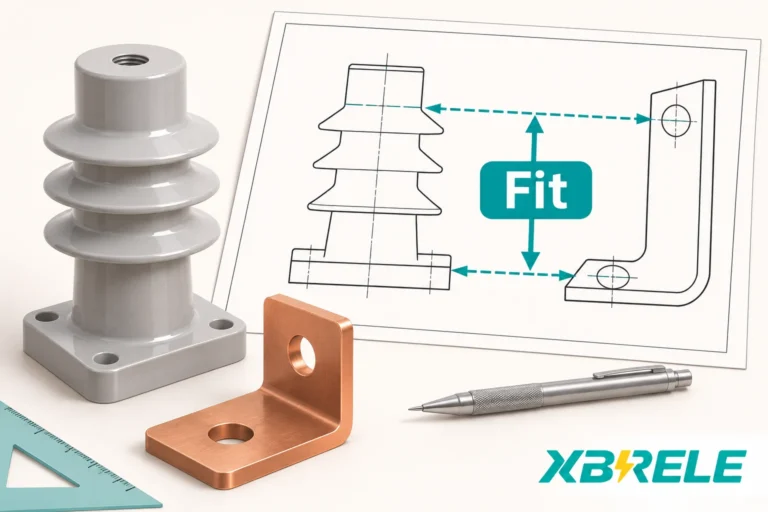
XBRELE’s catalogue separates two families that are easy to confuse at the enquiry stage. The ZJ post insulators are used for mechanical busbar support; the CG5 capacitive sensors add a voltage-indication function. Some sensor designs also provide mechanical support, but that role requires the offered model’s mechanical rating and mounting evidence. The post insulator catalogue page shows the families and their dimensions, and the switchgear parts catalogue shows the surrounding components. Send the assembly geometry and duty through the contact page so that the offered drawing and load basis can be matched to your panel rather than to a generic rating.
The deliverable worth asking for is a drawing revision plus a load statement that names the application height, the direction and the basis — proof, failing or working. Anything less cannot be checked against the moment your own fault study produces.
No. Current rating is a thermal statement about the conductor and its allowable temperature rise; it tells you how much section the bar needs and, indirectly, how large a bar the support must hold. The mechanical duty of the support comes from the fault force, the height and direction at which that force is applied, and the stiffness of the mounting structure. Two busbar assemblies with identical continuous-current ratings can require very different support capacities, and a post that is adequate for a large bar on a short span can be inadequate for a smaller bar on a long one. Verify mechanical demand and dielectric requirements together, with separate evidence for each.
No, and treating them as one is unsafe in one direction and wasteful in the other. A failing load records where the test piece broke and says nothing about permanent deformation at lower loads. An allowable or working-load declaration needs its stated conditions and design basis. A proof-load result is a third thing: survival against a defined test’s acceptance criteria. When comparing offers, compare like with like, and ask which basis the number uses, at what application height and in which direction.
Usually not. A taller post lengthens the lever arm, so the same transverse force produces a larger base moment — M = F × h grows in direct proportion to height — and taller posts are often more slender, so capacity may fall at the same time. Height does help with clearance and strike distance, and sometimes that is the binding constraint. Treat height as a variable that changes both the electrical and the mechanical result, and recheck the moment, the insert loads and the panel reaction for each height considered. If clearance forces a taller post, the clamp position and support span may need to change with it.
Only if the particular sensor is also designed and rated as a support for that assembly. A voltage-indication function alone establishes no mechanical capacity. For a combined sensor/support, confirm the load application height, direction, inserts and mounting evidence as well as the electrical sensing-system compatibility. Do not replace a support with a sensor on appearance or voltage class alone.
First compare the force-and-height pairs at their declared test arrangements. A moment calculation helps expose different lever arms, but it does not establish that a supplier’s load rating can be transferred to your application height. That means confirming the height and direction of the test force, the basis of the figure (proof, failing or working), the fixing condition at the base, and the failure mode the test actually reached. If any of those is missing, the numbers are not comparable, and the enquiry should go back for the missing detail rather than proceed on the larger value.