Vous avez besoin des spécifications complètes ?
Téléchargez notre catalogue de produits 2025 pour obtenir les schémas détaillés et les paramètres techniques de tous les composants des appareillages de commutation.
Obtenir le catalogue
Téléchargez notre catalogue de produits 2025 pour obtenir les schémas détaillés et les paramètres techniques de tous les composants des appareillages de commutation.
Obtenir le catalogue Téléchargez notre catalogue de produits 2025 pour obtenir les schémas détaillés et les paramètres techniques de tous les composants des appareillages de commutation.
Obtenir le catalogue
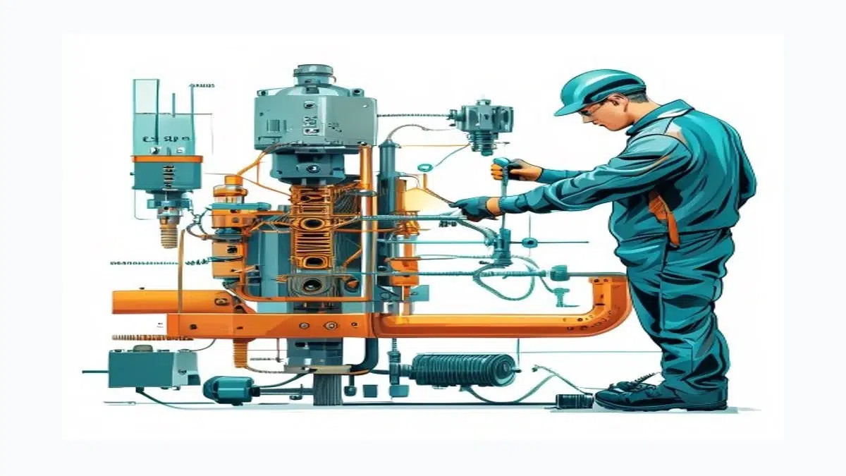
La préparation de la surface des joints de barres omnibus en vue d’obtenir des connexions à faible résistance consiste à éliminer de manière contrôlée les oxydes, les contaminants, et des irrégularités de surface sur les faces des conducteurs à assembler, combinée à l’application de matériaux d’interface compatibles, afin d’obtenir une résistance de contact stable inférieure ou égale à 10 micro-ohms pour les assemblages boulonnés en cuivre et inférieure à 20 micro-ohms pour les assemblages en aluminium de section équivalente.
Le courant traverse un assemblage boulonné par l'intermédiaire de points de contact discrets au niveau des aspérités, et non sur l'ensemble de la surface géométrique. Les couches d'oxyde, les résidus d'usinage et la contamination atmosphérique augmentent la résistivité au niveau de ces micro-points de contact, ce qui accroît la résistance de diffusion qui est le principal facteur à l'origine de l'échauffement de l'assemblage et de sa dégradation à long terme. La préparation de surface permet d'augmenter à la fois le nombre et la qualité des points de contact métalliques.

Avant de passer aux procédures détaillées, utilisez ce tableau pour identifier la cause première la plus probable et la mesure à prendre lorsque la mesure d'un joint ou une inspection visuelle soulève un problème.
| Symptôme | Premier test | Cause première probable | Action suivante |
|---|---|---|---|
| Résistance > 50 micro-ohms lors de la mise en service | Resserrer au couple spécifié, puis vérifier à nouveau | Préparation insuffisante de la surface ou couple de serrage insuffisant | Démonter, poncer à nouveau, réappliquer le produit de polissage, resserrer au couple prescrit, refaire le contrôle |
| Résistance comprise entre 25 et 50 micro-ohms, mais supérieure à 150% pour les jonctions adjacentes | Comparer les relevés de couple et le journal d'application des composés | Étape de préparation ignorée ou composé omis | Vérifier le couple et la surface avant l'acceptation ; consigner tout écart |
| Point chaud ΔT > 10 °C sur l'image thermographique réalisée en charge | Mesurer la résistance de contact avec le DLRO | Oxyde d'interface formé par cycles thermiques | Mettre hors tension, démonter, préparer à nouveau toute la surface du joint |
| Poudre blanche ou grise au niveau du périmètre du joint en aluminium | Inspection visuelle et test par essuyage à l'IPA | Infiltration d'humidité au niveau du bord du joint ; le mastic n'a pas été appliqué sur toute la surface de contact | Éliminer la corrosion, préparer à nouveau la surface, appliquer le composé sur la zone de contact 100% ainsi que sur une bordure de 5 mm |
| Patine verte sur un raccord en cuivre accompagnée d'une augmentation de la chute de millivolts | Photo avant démontage ; mesure DLRO | Oxydation atmosphérique ou attaque par les sulfures | Ponçage mécanique complet, nettoyage à l'IPA, nouvelle application du produit de polissage |
| La résistance augmente brusquement sous charge, puis diminue brièvement après le resserrage | Vérifier le type de revêtement et l'historique des vibrations | Usure par frottement due à des microglissements sur un placage d’étain tendre | Passer à un placage nickel-étain ou argent-étain ; utiliser un composé thixotrope |
| La résistance est conforme lors de la mise en service, mais augmente de plus de 20% lors de la première inspection | Vérifier la température des joints pendant le cycle de charge et le type de composé | Migration du composé au-delà de la limite thermique, ou qualité de composé inadaptée | Déterminez la température maximale d'utilisation du composé ; remplacez-le si celle-ci est inférieure à 80 °C. |
Il n'existe pas de norme universelle unique couvrant tous les aspects de la préparation des surfaces des raccords de barres omnibus ; les ingénieurs doivent donc recouper les exigences figurant dans plusieurs documents qui se recoupent, en fonction de la classe de tension, du matériau et du contexte d'installation.
| Standard | Organisme émetteur | Disposition(s) pertinente(s) | Champ d'application | Critères d'acceptation clés |
|---|---|---|---|---|
| Norme IEEE 605 | IEEE | Article 7, article 9 | Conception des conducteurs de bus et construction des jonctions pour les sous-stations | Résistance de contact ≤ 10% au-dessus de la ligne de base ; exigences relatives à l'état de surface avant le serrage des boulons |
| IEC 61439-1 | CEI | Clause 10.11 | Ensembles d'appareillage de commutation et de commande à basse tension | Élévation de température au niveau des raccords ; delta-T ≤ 105 °C sur les barres de cuivre |
| NEMA CC 1 | NEMA | Section 5 | Connecteurs électriques pour sous-stations | Rapport de résistance des jonctions (JRR) ≤ 1,0 par rapport à la résistance du conducteur sur une longueur équivalente |
| ANSI/NETA ATS | NETA | Section 7.9 | Essais de réception des raccordements de bus boulonnés | Résistance de contact ≤ 50 micro-ohms pour la plupart des assemblages boulonnés MT/HT ; élimination de l'oxyde vérifiée visuellement et à l'aide d'un micro-ohmmètre |
| Norme IEEE 80 | IEEE | Article 16 | Conducteurs et raccordements du système de mise à la terre | La résistance des jonctions ne doit pas dépasser celle d'une longueur équivalente de conducteur |
| ASTM B193 | ASTM | Document complet | Méthode d'essai de résistivité pour les matériaux conducteurs d'électricité | Résistivité de référence de la roche mère pour le calcul de la contribution des joints |
| OSHA 29 CFR 1910.269 | OSHA | (a)(1)(i), (t)(4) | Production, transport et distribution d'électricité | Les raccords doivent être réalisés conformément aux spécifications du fabricant en matière de couple de serrage et de finition de surface avant la mise sous tension. |
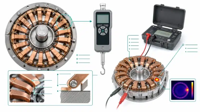
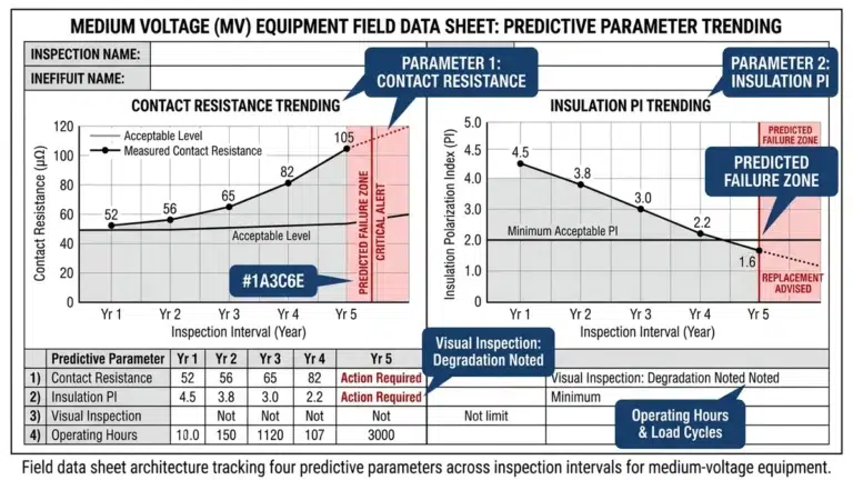
Essai au micro-ohmmètre (DLRO) : Appliquer un courant continu de valeur connue (généralement 100 A) aux bornes du raccord et mesurer la chute de tension. Un résultat supérieur à 150% de la valeur de référence obtenue sur un raccord identique fraîchement préparé indique une préparation de surface inadéquate, une oxydation ou une force de contact insuffisante.
Thermographie infrarouge : Un écart de température supérieur à 10 °C par rapport à un raccord identique adjacent soumis à la même charge nécessite la mise hors tension et une inspection. La thermographie permet de vérifier le résultat de la préparation, mais ne peut se substituer aux essais de résistance effectués avant le raccordement.
La préparation adéquate de la surface des raccords de barres omnibus dépend de la disponibilité des instruments appropriés sur le lieu d'intervention. Le tableau ci-dessous répertorie à la fois les instruments de terrain et les sources de référence.
| Instrument / Source | Objectif | Seuil d'acceptation | Condition de rejet |
|---|---|---|---|
| Micro-ohmmètre numérique, courant d'essai >= 10 A | Mesurer la résistance de contact des jonctions | <= 10 micro-ohms cuivre-cuivre ; <= 15 micro-ohms aluminium-aluminium | La valeur mesurée dépasse le seuil après le resserrage |
| Clé dynamométrique, étalonnée à +/- 41 TP3T | Vérifier que le couple de serrage des boulons est conforme aux spécifications | Conformément à la classe de résistance des éléments de fixation et au diamètre des boulons indiqués sur le plan d'assemblage | Toute valeur de couple s'écartant de +/- 10% de la valeur spécifiée |
| Brosse métallique en acier inoxydable (spécialement conçue pour l'aluminium) | Élimination mécanique de l'oxyde de l'aluminium | Métal brillant, aucune trace d'oxydation visible | Des dépôts sombres, des piqûres ou des traces de corrosion persistent |
| Brosse métallique en acier inoxydable ou en acier au carbone (spécialement conçue pour le cuivre) | Élimination mécanique de l'oxyde du cuivre | Métal brillant, aucune trace d'oxydation visible | Taches ou dépôts résiduels |
| Profilomètre de surface ou comparateur Ra | Vérifier la rugosité de la surface après la préparation mécanique | Ra 1,6-3,2 µm pour les surfaces plaquées ; Ra 3,2-6,3 µm pour le cuivre ou l'aluminium nu | Ra 6,3 µm (les pics s'effondrent sous l'effet de la compression) |
| Jauge d'épaisseur de revêtement (à courants de Foucault) | Vérifier l'épaisseur du revêtement sur les barres omnibus pré-plaquées | Étainnage : 5 à 25 micromètres ; argenture : 5 à 15 micromètres | Revêtement inférieur à 5 micromètres ou absent dans la zone de contact |
| Thermomètre à contact ou thermomètre infrarouge | Valeur de référence de la température au moment de la mesure de la résistance | Température ambiante ± 5 °C par rapport à la température de référence de mesure | Température de surface hors de cette plage sans correction appliquée |
| Analyseur de temps ou chronomètre | Vérifier le temps écoulé entre la préparation et le serrage des boulons | <= 15 min pour l'aluminium nu ; <= 30 min pour le cuivre nu | Délai dépassé sans nouvelle préparation |
| Plan d'assemblage d'origine / tableau des couples de serrage | Spécifications de couple et confirmation de la classe de résistance des éléments de fixation | Valeurs de couple et ordre de serrage conformément au schéma | Aucun plan n'est disponible sur place |
| NETA ATS, section 7.9 | Seuil d'acceptation de la résistance de contact | <= 50 micro-ohms ou <= 150% du joint de référence adjacent | Aucun des deux critères n'a été rempli après deux tentatives de préparation |
| Spécification du projet | Préparation de la surface en fonction du site et limites de résistance | Comme indiqué dans le plan qualité du projet | Résultats hors des limites du projet, indépendamment du respect des normes |
| Fichier du certificat d'étalonnage | Vérifier la traçabilité des instruments | Courant d'étalonnage dans les limites de l'intervalle indiqué par le fabricant (généralement 12 mois) | Certificat expiré ou indisponible sur le site |
Le tableau ci-dessous récapitule les paramètres de préparation qui varient selon les types de matériaux et constitue le principal outil de référence rapide sur le terrain.
| Paramètre | Cuivre (nu) | Cuivre (étamé) | Aluminium (brut) | Aluminium (étamé ou argenté) |
|---|---|---|---|---|
| Problème lié à la dureté de l'oxyde | Faible à modéré | Faible | Élevé (Al₂O₃, très dur) | Faible à modéré |
| Une abrasion mécanique est nécessaire | Oui, la lumière | Se contenter d'inspecter ; éviter d'abîmer le revêtement | Oui, agressif | Vérifier ; éclairage uniquement |
| Outil abrasif | Brosse métallique en acier inoxydable (spécifique pour le cuivre) | Scotch-Brite ou équivalent | Brosse métallique en acier inoxydable (spécialement conçue pour l'aluminium) | Tampon abrasif fin |
| Nettoyage au solvant après abrasion | Exigée | Exigée | Exigée | Exigée |
| Type de pâte à joints | Graisse anti-oxydation (adaptée au cuivre) | Composé neutre ou classé « Cu » | Graisse anti-oxydation (classée Al) | Spécifié par le fabricant |
| Durée maximale entre la préparation et la fixation par boulons | <= 30 min (à température ambiante, à l'air libre) | <= 60 min | <= 10 à 15 min | <= 30 min |
| Résistance de contact cible (par jonction) | <= 10 micro-ohms | <= 10 micro-ohms | <= 20 micro-ohms | <= 15 micro-ohms |
| Déclencheur de nouvelle préparation | Résistance > 1,5 fois la valeur de référence ou formation de fossettes visibles | Idem, plus la perte due au placage | Idem | Idem |
Les conditions sur le terrain introduisent des variables que les procédures contrôlées en atelier ne peuvent pas reproduire. Une même technique de préparation appliquée dans un atelier d'assemblage à climatisation contrôlée et sur une installation de poste de couplage en extérieur peut donner lieu à des jonctions dont les valeurs de résistance diffèrent d'un facteur deux, voire plus.
| Type de contaminant | Première étape | Deuxième étape | Séquence d'abrasion |
|---|---|---|---|
| Carbone ou suie | Nettoyage à l'IPA, deux passages | Nettoyage avec un chiffon sec | Une brosse métallique classique, puis une éponge Scotch-Brite |
| Film de sulfure | Lingette imbibée d'acide citrique dilué (5%), neutraliser à l'eau claire, sécher soigneusement | Lingette IPA | Brosse métallique en acier inoxydable uniquement |
| Hydrocarbure ou pétrole | Nettoyer à l'acétone (vérifier au préalable la compatibilité des matériaux), puis à l'IPA | Nettoyage avec un chiffon sec | Scotch-Brite, puis une brosse métallique |
Situation : Au cours d'une inspection thermographique de routine d'un système de barres omnibus en aluminium de 2 000 A dans une usine de transformation des métaux, un écart de température de 23 °C a été enregistré au niveau d'un raccord entre le circuit principal et une dérivation d'alimentation. Des jonctions similaires situées à proximité présentaient des valeurs de delta-T comprises entre 3 et 5 °C sous la même charge. L'installation datait d'environ 18 mois.
Données mesurées : Le test DLRO, réalisé avec une injection de 100 A en courant continu, a enregistré une résistance de 47 micro-ohms au niveau du raccord suspect. Les raccords adjacents sur la même section de barre présentaient des valeurs comprises entre 11 et 14 micro-ohms. Selon la norme NETA ATS 150%, le seuil d'acceptation était fixé à environ 17-21 micro-ohms sur la base de ces valeurs de référence ; le joint suspect dépassait cette valeur de plus du double.
Diagnostic : Le démontage du joint a révélé une couche d’oxyde grise uniforme sur environ 60% de la surface de contact, la zone centrale présentant une partie plus propre mais légèrement en retrait où un composé avait été appliqué. Les zones périphériques étaient sèches et ne présentaient aucun résidu de composé. Le compte-rendu de préparation indiquait que du produit d’étanchéité avait été appliqué, mais ne mentionnait pas le temps écoulé entre le ponçage et le serrage des boulons. Les conditions ambiantes lors de l’installation initiale comprenaient une humidité relative enregistrée supérieure à 80%. Cause première : reformation d’oxyde à la surface de l’aluminium en raison d’un délai prolongé entre le ponçage et l’application du produit d’étanchéité, combinée à une couverture incomplète de ce dernier. Le composé de la zone centrale avait partiellement migré sous l’effet des cycles thermiques, ce qui correspond au fonctionnement à forte intensité de l’installation.
Le choix d'un composé ou d'un revêtement inadapté ne se limite pas à réduire la durée de vie : cela peut accélérer la corrosion, retenir des contaminants ou créer des couples galvaniques qui augmentent la résistance de contact plus rapidement que ne le ferait un raccord nu.
Graisse anti-oxydante (à base de pétrole ou synthétique) : La solution standard du secteur pour les raccords aluminium-aluminium et aluminium-cuivre. Ce composé agit comme une barrière à l'oxygène tandis que les aspérités métalliques y font passer le courant sous l'effet de la pression de serrage. Les composés à base de pétrole se ramollissent au-delà d'une température de service continu d'environ 60 à 70 °C ; dans les raccords à forte intensité qui atteignent régulièrement cette température, le composé s'échappe de l'interface, laissant un raccord sec et oxydé au bout d'un à deux cycles thermiques.
Composé anti-grippage (à base de cuivre ou de zinc) : Il offre une protection modérée contre la formation d'oxyde et réduit le grippage lors du montage. L'application d'un produit anti-grippage à base de cuivre sur la face d'une barre omnibus en aluminium accélère la corrosion galvanique dans les environnements humides — ne pas utiliser lorsque le métal de base et le composant de remplissage sont de nature différente.
| Type de placage | Épaisseur type | Meilleure application | Avantage de résistance | Risque principal |
|---|---|---|---|---|
| Étain (galvanisé) | 5 à 25 micromètres | Appareillage de commutation pour usage intérieur, canal de bus, température modérée | Faible résistance de contact à l'état neuf ; oxyde tendre éliminé sous l'effet du couple | Croissance des « whiskers » d'étain dans les dépôts d'étain pur ; l'usure par frottement augmente la résistance sous l'effet des vibrations |
| Argent | 10 à 50 micromètres | Connexions à courant élevé, températures élevées > 80 °C, postes de transformation en extérieur | Résistance de contact la plus faible parmi les revêtements courants ; l'oxyde est conducteur | Coût élevé ; se ternit dans les atmosphères riches en soufre |
| Nickel | 5 à 15 micromètres | Bus à haute température > 100 °C, environnements chimiques agressifs | Résistance stable en fonction de la température | L'oxyde dur nécessite une force de contact plus élevée ; il augmente la résistance si la pression de serrage est insuffisante |
| Étain par trempage à chaud | 25 à 75 micromètres | Environnements extérieurs ou corrosifs, raccords de réseaux | Une couche épaisse résiste aux dommages superficiels ; bonne protection contre la corrosion | Un profil de surface irrégulier peut réduire la surface de contact réelle s'il n'est pas réaplanifié après le placage. |
| Cuivre nu (non plaqué) | — | Installations intérieures à court terme uniquement | Faible résistance lorsqu'il est fraîchement préparé | Oxydation rapide ; nécessite l'application du produit à chaque assemblage ; ne convient pas aux joints étanches ou inaccessibles |
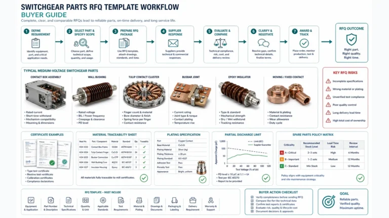
La documentation et les décisions d'approvisionnement comblent les deux lacunes restantes entre la procédure prévue et la mise en œuvre effective sur le terrain : vérifier que les étapes de préparation ont été correctement menées à bien et s'assurer que les barres omnibus livrées présentent des surfaces adaptées à un assemblage à faible résistance.
Vérification avant nettoyage : Les surfaces des joints doivent être visuellement exemptes de toute trace d'huile lourde, de graisse ou de lubrifiant ; aucune trace d'humidité ou de condensation ne doit être visible ; le matériau de base doit être identifié et validé conformément à la procédure de préparation ; la méthode de nettoyage abrasive ou chimique appropriée doit être choisie.
Préparation mécanique : Direction d'abrasion constatée ; grade de la brosse métallique ou du tampon abrasif confirmé ; aucune contamination croisée entre des métaux différents (utilisation d'outils dédiés) ; texture de surface visuellement homogène, sans rayures profondes ni bavures rabotées.
| Section | Champs clés |
|---|---|
| Identification des articulations | Projet/site, numéro d'identification du panneau, numéro de référence commun, date, numéro d'identification du technicien |
| Matériau et configuration | Matériau des barres omnibus, type de revêtement, section (mm²), configuration des raccords, surface de contact (mm²) |
| Processus de préparation | Produit de nettoyage, type et grade de l'abrasif, confirmation de l'outil utilisé, durée de traitement de la surface, marque et grade du composé, temps écoulé jusqu'à la fin de l'opération (en minutes) |
| Résultats de l'inspection | Résultat de la liste de contrôle (Conforme/Non conforme/Sous réserve), mesures correctives en cas de non-conformité, date de nouvelle inspection |
| Record de couple | Couple requis (N·m), couple appliqué (N·m), vérification des repères par position de boulon |
| Résultats des essais électriques | Modèle et numéro de série de l'appareil de mesure, courant d'essai (A), résistance mesurée (micro-ohms), limite spécifiée (micro-ohms), résultat de l'essai, date et résultat de l'inspection thermographique |
| Signature | Technicien d'exécution, contrôleur qualité, ingénieur superviseur (avec dates) |
| Domaine d'évaluation | Minimum acceptable | Indicateur de confiance accru | Motif d'exclusion |
|---|---|---|---|
| Spécifications de surface sur le dessin | Type de revêtement et épaisseur nominale indiqués | Plage d'épaisseur, Ra du substrat et norme applicable sont tous mentionnés | Surface décrite uniquement comme “ étamée ”, sans indication d'épaisseur ni de norme |
| Fiches d'essai | Certificat de conformité fourni | Mesures de l'épaisseur du revêtement par lot et résultats des essais d'adhérence | Aucun document ; simple assurance verbale |
| Contrôle de la planéité | Tolérance de planéité spécifiée pour la face d'assemblage | Données de planéité mesurées fournies avec la livraison | Il n'existe aucune spécification relative à la planéité |
| Emballage | Protection individuelle des faces d'assemblage | Emballage hermétique avec barrière anti-humidité et dessiccant | Des barres nues regroupées sans protection faciale |
| Adéquation environnementale | Revêtement choisi pour l'environnement indiqué | Le fournisseur confirme par écrit que ses produits sont adaptés aux conditions du chantier | Sélection à partir d'un catalogue générique sans analyse des conditions du site |
| Recommandations concernant la durée de conservation | Durée de stockage avant le nouveau contrôle indiquée | Procédure écrite de manipulation et de réinspection fournie | Aucune indication ; stockage pour une durée indéterminée supposé |
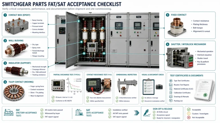
Utilisez ces références XBRELE pour relier la décision sur le terrain au produit correct, au test et au flux de travail de l'approvisionnement : Page produit XBRELE, Gamme de disjoncteurs à vide XBRELE, Guide de notation de la VCB, Liste de contrôle pour l'acceptation du TFA/TSA par le VCB, gamme de composants pour appareillages de commutation XBRELE.
Pour le contexte de la méthode externe, comparez la procédure du site avec la procédure publique. Page des normes IEEE C37.09 et appliquer le manuel de l'équipementier et les spécifications du projet pour l'équipement fourni.
Exemple de terrain : lors d'une inspection de service, une phase a été mesurée en dehors de sa ligne de base de mise en service, alors que les deux autres phases sont restées stables. L'équipe a répété la mesure avec des fils vérifiés, a contrôlé la synchronisation et la course du contact, et a utilisé la divergence mesurée pour distinguer un problème de pression de contact d'un problème générique de nettoyage de surface.
La valeur seuil d'acceptation la plus couramment appliquée sur le terrain est de 50 micro-ohms par jonction pour les assemblages boulonnés à moyenne et haute tension, comme indiqué dans la section 7.9 de la norme ANSI/NETA ATS. Il s'agit toutefois d'un critère de sécurité prudent, et non d'un objectif de conception.
L'aluminium nu doit être recouvert dans les 10 à 15 minutes suivant la fin du ponçage mécanique, dans des conditions ambiantes sèches. Dans les environnements où l'humidité relative est supérieure à 70% ou où la température de surface se situe à moins de 3 °C du point de rosée, ce délai est encore plus court.
Non. Le produit injecté à travers un trou percé au niveau du périmètre du joint après le serrage des boulons ne permet pas d'obtenir une couverture uniforme sur toute la surface de contact et ne constitue pas une méthode de réparation définitive reconnue.
Une mesure de résistance absolue consiste à comparer la valeur mesurée au niveau du raccord à un seuil fixe (par exemple, 50 micro-ohms). Le rapport de résistance au niveau du raccord (JRR), tel que défini dans la norme NEMA CC 1, compare la résistance du raccord à celle d'une section de conducteur de même longueur.
L'argenture est recommandée lorsque la température à la surface du raccord dépasse régulièrement 75 à 80 °C, lorsque l'installation se trouve dans un poste de distribution extérieur exposé de manière prolongée à l'humidité, ou lorsque le raccord est destiné à fonctionner pendant de longues périodes sans qu'il soit possible de le retravailler. L'étamage convient aux appareillages de commutation intérieurs secs soumis à une intensité admissible modérée.
Au minimum, le dossier de documentation doit inclure l'identification et l'emplacement de l'assemblage, la confirmation du matériau de base et du type de revêtement, une liste de contrôle de préparation dûment remplie ne présentant aucun « Échec » non résolu, le temps écoulé entre l'abrasion et la fermeture (élément critique pour l'aluminium), la valeur de couple enregistrée pour chaque position de boulon avec confirmation du marquage de référence, le modèle et le numéro de série de l’instrument DLRO accompagnés du certificat d’étalonnage en cours de validité, la résistance mesurée en micro-ohms, ainsi que le résultat « conforme » ou « non conforme » par rapport à la limite spécifiée. La signature du technicien chargé de l’intervention, de l’inspecteur du contrôle qualité et de l’ingénieur superviseur est requise avant l’archivage du dossier et l’homologation de l’assemblage pour la mise en service.