¿Necesita las especificaciones completas?
Descargue nuestro Catálogo de productos 2025 para obtener planos detallados y parámetros técnicos de todos los componentes de los equipos de conmutación.
Obtener catálogo
Descargue nuestro Catálogo de productos 2025 para obtener planos detallados y parámetros técnicos de todos los componentes de los equipos de conmutación.
Obtener catálogo Descargue nuestro Catálogo de productos 2025 para obtener planos detallados y parámetros técnicos de todos los componentes de los equipos de conmutación.
Obtener catálogo
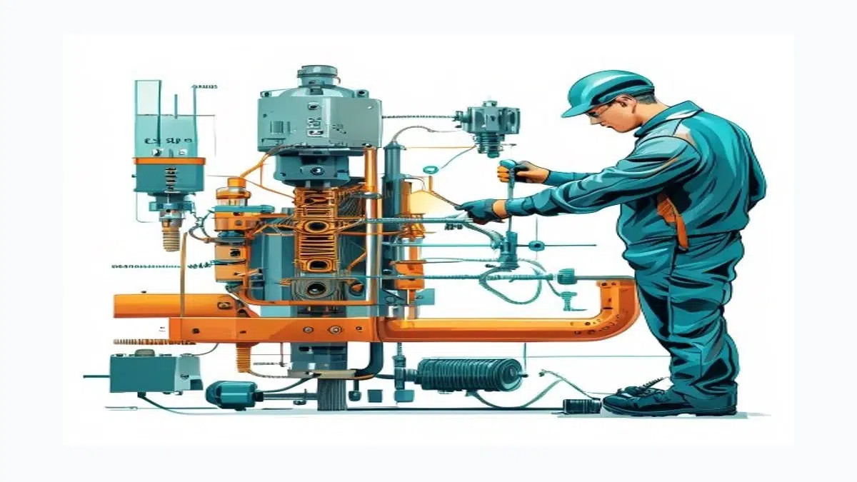
La preparación de la superficie de las uniones de barras colectoras para conseguir conexiones de baja resistencia consiste en la eliminación controlada de óxidos, contaminantes, e irregularidades superficiales de las caras de los conductores que se acoplan, combinada con la aplicación de materiales de interfaz compatibles, con el fin de lograr una resistencia de contacto estable igual o inferior a 10 microohmios para uniones atornilladas de cobre e inferior a 20 microohmios para uniones de aluminio de sección transversal equivalente.
La corriente atraviesa una unión atornillada a través de puntos de contacto discretos en las asperezas, y no a lo largo de toda la superficie geométrica. Las capas de óxido, los residuos de mecanizado y la contaminación atmosférica aumentan la resistividad en estos micropuntos de contacto, lo que eleva la resistencia de dispersión que determina el calentamiento de la unión y su degradación a largo plazo. La preparación de la superficie aumenta tanto el número como la calidad de los puntos de contacto metálicos.
Antes de seguir los procedimientos detallados, utiliza esta tabla para identificar la causa raíz más probable y la acción a seguir cuando una medición de juntas o una inspección visual indiquen un problema.
| Síntoma | Primera prueba | Causa probable | Próxima acción |
|---|---|---|---|
| Resistencia > 50 microohmios en el momento de la puesta en servicio | Vuelve a apretar según las especificaciones y vuelve a medir. | Preparación insuficiente de la superficie o par de apriete insuficiente | Desmontar, volver a lijar, volver a aplicar el compuesto, volver a apretar con el par de apriete adecuado y volver a comprobar |
| Resistencia de 25-50 microohmios, pero > 150% de las uniones adyacentes | Comparar registros de par y el registro de aplicación de compuestos | Se ha omitido un paso de la preparación o se ha omitido un compuesto | Comprueba el par y la superficie antes de aceptarlo; documenta cualquier desviación. |
| Punto caliente con ΔT > 10 °C en la exploración termográfica bajo carga | Medir la resistencia de contacto con el DLRO | Óxido de interfaz formado mediante ciclos térmicos | Desconectar la alimentación eléctrica, desmontar y volver a preparar toda la superficie de la junta |
| Polvo blanco o gris en el perímetro de la junta de aluminio | Inspección visual y prueba de limpieza con alcohol isopropílico | Entrada de humedad por el borde de la junta; el compuesto no se ha aplicado en toda la superficie de contacto | Eliminar la corrosión, volver a preparar la superficie y aplicar el compuesto en el área de contacto 100% más un borde de 5 mm. |
| Pátina verde en la unión de cobre con una caída de milivoltios creciente | Fotografía antes del desmontaje; medición del DLRO | Oxidación atmosférica o ataque por sulfuros | Limpieza mecánica completa, pasar un paño con alcohol isopropílico y volver a aplicar el compuesto |
| La resistencia se dispara bajo carga y desciende brevemente tras volver a aplicar el par de apriete. | Comprueba el tipo de recubrimiento y el historial de vibraciones | Desgaste por fricción debido a microdeslizamientos en un recubrimiento blando de estaño | Cambia a un recubrimiento de níquel-estaño o plata-estaño; utiliza un compuesto tixotrópico |
| La resistencia supera la prueba de puesta en servicio y supera los 20% en la primera inspección | Comprueba la temperatura de la junta durante el ciclo de carga y el tipo de compuesto | Migración del compuesto por encima del límite térmico, o grado incorrecto del compuesto | Determina la temperatura máxima de servicio del compuesto; sustitúyelo si es inferior a los 80 °C indicados. |
No existe una norma universal única que abarque todos los aspectos de la preparación de la superficie de las uniones de barras colectoras, por lo que los ingenieros deben identificar los requisitos en varios documentos que se solapan, en función de la clase de tensión, el material y el contexto de la instalación.
| Estándar | Organismo emisor | Cláusulas pertinentes | Ámbito de aplicación | Criterios clave de aceptación |
|---|---|---|---|---|
| Norma IEEE 605 | IEEE | Cláusula 7, Cláusula 9 | Diseño de conductores de bus y construcción de uniones para subestaciones | Resistencia de contacto <= 10% por encima de la línea de referencia; requisitos de acabado superficial antes del atornillado |
| IEC 61439-1 | IEC | Cláusula 10.11 | Conjuntos de aparamenta de baja tensión | Aumento de la temperatura en las uniones; delta-T ≤ 105 °C en las barras de cobre |
| NEMA CC 1 | NEMA | Sección 5 | Conectores eléctricos para subestaciones | Relación de resistencia de la unión (JRR) ≤ 1,0 en relación con la resistencia del conductor en una longitud equivalente |
| ANSI/NETA ATS | NETA | Apartado 7.9 | Pruebas de aceptación de las conexiones de barridos atornilladas | Resistencia de contacto <= 50 microohmios para la mayoría de las uniones atornilladas de media y alta tensión; eliminación del óxido comprobada visualmente y con un microohmímetro |
| Norma IEEE 80 | IEEE | Cláusula 16 | Conductores y conexiones del sistema de puesta a tierra | La resistencia de la unión no debe superar la de una longitud equivalente de conductor |
| ASTM B193 | ASTM | Documento completo | Método de ensayo de resistividad para materiales conductores de electricidad | Resistividad de referencia del material de origen para el cálculo de la contribución de las juntas |
| OSHA 29 CFR 1910.269 | OSHA | (a)(1)(i), (t)(4) | Generación, transporte y distribución de energía eléctrica | Las uniones deben realizarse de acuerdo con las especificaciones del fabricante en cuanto a par de apriete y superficie antes de la puesta en servicio. |
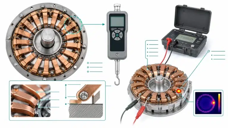
Prueba con microohmímetro (DLRO): Aplique una corriente continua conocida (normalmente de 100 A) a través de la unión y mida la caída de tensión. Un resultado superior a 150% del valor de referencia en una unión idéntica recién preparada indica una preparación inadecuada de la superficie, oxidación o una fuerza de contacto insuficiente.
Termografía infrarroja: Una diferencia de temperatura superior a 10 °C con respecto a una unión idéntica adyacente sometida a la misma carga requiere la desconexión de la tensión y una inspección. La termografía confirma el resultado de la preparación, pero no puede sustituir a las pruebas de resistencia previas a la conexión.
La preparación adecuada de la superficie de unión de las barras colectoras depende de que se disponga de los instrumentos adecuados en el lugar de trabajo. La tabla siguiente recoge tanto los instrumentos de campo como las fuentes de verificación.
| Instrumento / Fuente | Propósito | Umbral de aceptación | Condición de rechazo |
|---|---|---|---|
| Microohmímetro digital, corriente de prueba >= 10 A | Medir la resistencia de contacto de la unión | <= 10 microohmios cobre-cobre; <= 15 microohmios aluminio-aluminio | La lectura supera el umbral tras volver a apretar con el par adecuado |
| Llave dinamométrica, calibrada a +/- 4% | Comprueba que el par de apriete de los tornillos se ajuste a las especificaciones | Según la clase del elemento de fijación y el diámetro del perno que figuran en el plano de montaje de la unión | Cualquier lectura que se desvíe más de +/- 10% del par especificado |
| Cepillo de alambre de acero inoxidable (específico para aluminio) | Eliminación mecánica del óxido del aluminio | Metal brillante, sin signos visibles de oxidación | Persisten una película oscura, picaduras o productos de corrosión |
| Cepillo de alambre de acero inoxidable o de carbono (específico para cobre) | Eliminación mecánica del óxido del cobre | Metal brillante, sin signos visibles de oxidación | Decoloración residual o incrustaciones |
| Perfilómetro de superficie o comparador Ra | Comprobar la rugosidad de la superficie tras la preparación mecánica | Ra de 1,6 a 3,2 micrómetros para superficies recubiertas; Ra de 3,2 a 6,3 micrómetros para cobre o aluminio sin recubrimiento | Ra 6,3 micrómetros (los picos se colapsan bajo compresión) |
| Medidor de espesor de recubrimiento (tipo de corrientes parásitas) | Comprobar el espesor del recubrimiento en las barras colectoras pregalvanizadas | Estañado: 5-25 micrómetros; plateado: 5-15 micrómetros | Recubrimiento inferior a 5 micrómetros o ausente en la zona de contacto |
| Termómetro de contacto o termómetro infrarrojo | Registro de la temperatura basal en el momento de la medición de la resistencia | Temperatura ambiente: +/- 5 °C respecto a la temperatura de referencia de la medición | Temperatura superficial fuera de este rango sin aplicar corrección |
| Analizador de tiempos o cronómetro | Comprobar el tiempo transcurrido desde la preparación hasta el montaje con pernos | <= 15 min para el aluminio sin recubrimiento; <= 30 min para el cobre sin recubrimiento | Se ha superado el plazo sin que se haya vuelto a preparar |
| Plano de montaje de juntas OEM / tabla de pares de apriete | Especificaciones de par de apriete y confirmación de la clase de los elementos de fijación | Valores de par y secuencia según el plano | No hay planos disponibles en las instalaciones |
| NETA ATS, sección 7.9 | Umbral de aceptación de la resistencia de contacto | <= 50 microohmios o <= 150% de la junta de referencia adyacente | No se cumplió ninguno de los dos criterios tras dos intentos de preparación |
| Especificaciones del proyecto | Preparación de la superficie específica para cada emplazamiento y límites de resistencia | Tal y como se indica en el plan de calidad del proyecto | Resultados que se salen de los límites del proyecto, independientemente del cumplimiento de las normas |
| Archivo del certificado de calibración | Confirmar la trazabilidad de los instrumentos | Corriente de calibración dentro del intervalo indicado por el fabricante (normalmente 12 meses) | El certificado ha caducado o no está disponible en el sitio web |
La tabla siguiente resume los parámetros de preparación que varían según el tipo de material y sirve como principal guía de referencia rápida para el trabajo sobre el terreno.
| Parámetro | Cobre (sin recubrimiento) | Cobre (estañado) | Aluminio (sin recubrimiento) | Aluminio (estañado o plateado) |
|---|---|---|---|---|
| Preocupación por la dureza del óxido | Bajo-moderado | Bajo | Alto (Al₂O₃, muy duro) | Bajo-moderado |
| Se requiere abrasión mecánica | Sí, luz | Limítate a inspeccionar; evita dañar el recubrimiento | Sí, agresivo | Revisar; solo luz |
| Herramienta abrasiva | Cepillo de alambre de acero inoxidable (para cobre) | Scotch-Brite o equivalente | Cepillo de alambre de acero inoxidable (para aluminio) | Almohadilla abrasiva fina |
| Limpieza con disolvente tras la abrasión | Requerido | Requerido | Requerido | Requerido |
| Tipo de masilla para juntas | Grasa inhibidora de óxido (apta para cobre) | Compuesto neutro o clasificado como «Cu» | Grasa inhibidora de óxido (clasificación Al) | Especificado por el fabricante |
| Tiempo máximo desde la preparación hasta el montaje | <= 30 min (a temperatura ambiente, en seco) | <= 60 min | <= 10-15 min | <= 30 min |
| Resistencia de contacto objetivo (por unión) | <= 10 microohmios | <= 10 microohmios | <= 20 microohmios | <= 15 microohmios |
| Desencadenante de nueva preparación | Resistencia > 1,5 veces el valor basal o formación de hoyuelos visibles | Lo mismo, más la pérdida por galvanización | Lo mismo | Lo mismo |
Las condiciones sobre el terreno introducen variables que los procedimientos controlados en taller no pueden reproducir. La misma técnica de preparación aplicada en una nave de montaje con clima controlado y en una subestación al aire libre puede dar lugar a uniones con valores de resistencia que difieren en un factor de dos o más.
| Tipo de contaminante | Primer paso | Segundo paso | Secuencia de abrasión |
|---|---|---|---|
| Carbono o hollín | Limpieza con IPA, dos pasadas | Limpiar con un paño seco | Cepillo de alambre normal y, después, Scotch-Brite |
| Película de sulfuro | Limpiar con una toallita impregnada en ácido cítrico diluido (5%), neutralizar con agua limpia y secar bien. | Toallita con IPA | Solo cepillo de alambre de acero inoxidable |
| Hidrocarburo o petróleo | Limpiar con un paño impregnado en acetona (comprobar primero la compatibilidad del material) y, a continuación, con un paño impregnado en alcohol isopropílico | Limpiar con un paño seco | Scotch-Brite y, después, un cepillo de alambre |
Situación: Durante una inspección termográfica programada de un sistema de barras colectoras de aluminio de 2.000 A en una planta de procesamiento de metales, se registró un diferencial de temperatura de 23 °C en un empalme entre el tramo principal y una derivación de alimentación. Las uniones adyacentes similares presentaban valores de delta-T de entre 3 y 5 °C bajo la misma carga. La instalación tenía aproximadamente 18 meses de antigüedad.
Datos empíricos: La prueba DLRO, con una inyección de 100 A de corriente continua, registró 47 microohmios en la unión sospechosa. Las uniones adyacentes en la misma sección de la barra registraron valores de entre 11 y 14 microohmios. El criterio NETA ATS 150% establecía el umbral de aceptación en aproximadamente 17-21 microohmios basándose en esos valores de referencia; la unión sospechosa superaba este valor en más del doble.
Diagnóstico: El desmontaje de la unión reveló una capa de óxido gris uniforme que cubría aproximadamente 60% de la superficie de contacto, mientras que la zona central presentaba un área más limpia, aunque ligeramente rebajada, donde se había aplicado el compuesto. Las zonas perimetrales estaban secas y no presentaban residuos del compuesto. El registro de preparación indicaba que se había aplicado el compuesto, pero no se había anotado el tiempo transcurrido desde el lijado hasta el apriete de los pernos. Las condiciones ambientales durante la instalación original incluían una humedad relativa registrada superior al 80%. Causa principal: la reaparición de óxido en la superficie de aluminio debido al prolongado tiempo transcurrido entre el lijado y la aplicación del compuesto, junto con una cobertura incompleta del mismo. El compuesto de la zona central se había desplazado parcialmente debido a los ciclos térmicos, en consonancia con el funcionamiento de la instalación a alta intensidad.
Elegir un compuesto o un recubrimiento inadecuados no solo reduce la vida útil, sino que puede acelerar la corrosión, retener contaminantes o generar pares galvánicos que aumentan la resistencia de contacto más rápidamente que en una unión sin recubrimiento.
Grasa inhibidora de la oxidación (de base mineral o sintética): El estándar del sector para uniones de aluminio con aluminio y de aluminio con cobre. El compuesto actúa como barrera contra el oxígeno, mientras que las asperezas del metal conducen la corriente a través de él bajo presión de sujeción. Los compuestos derivados del petróleo se ablandan por encima de unos 60-70 °C en servicio continuo; en uniones de alta capacidad de corriente que alcanzan habitualmente esa temperatura, el compuesto se desplaza fuera de la interfaz, dejando una unión seca y oxidada en el plazo de uno o dos ciclos térmicos.
Compuesto antiadherente (con cobre o zinc): Ofrece una función moderada de inhibición de la oxidación y reduce el agarrotamiento durante el montaje. El compuesto antiagarrotamiento con relleno de cobre aplicado sobre la superficie de una barra colectora de aluminio acelera la corrosión galvánica en entornos húmedos; no lo utilices cuando el metal base y el relleno del compuesto sean de materiales diferentes.
| Tipo de recubrimiento | Espesor habitual | Mejor aplicación | Ventaja de resistencia | Riesgo principal |
|---|---|---|---|---|
| Estaño (galvanizado) | 5-25 micrómetros | Aparamenta para interiores, conducto de barras, temperatura moderada | Baja resistencia de contacto cuando está nuevo; el óxido blando se desplaza bajo el par de apriete | Crecimiento de «barbas de estaño» en depósitos de estaño puro; el desgaste por fricción aumenta la resistencia ante la vibración |
| Plata | 10-50 micrómetros | Conexiones de alta intensidad, temperaturas elevadas > 80 °C, subestaciones al aire libre | La resistencia de contacto más baja de entre los recubrimientos habituales; el óxido es conductor | Alto coste; se empaña en atmósferas ricas en azufre |
| Níquel | 5-15 micrómetros | Bus de alta temperatura > 100 °C, entornos químicos agresivos | Resistencia estable a la temperatura | El óxido duro requiere una mayor fuerza de contacto; aumenta la resistencia si la presión de sujeción es insuficiente |
| Estaño por inmersión en caliente | 25-75 micrómetros | Entornos al aire libre o corrosivos, uniones de servicios públicos | Su capa gruesa resiste los daños superficiales; ofrece una buena protección contra la corrosión | Un perfil irregular de la superficie puede reducir el área de contacto real si no se vuelve a alisar tras el recubrimiento. |
| Cobre desnudo (sin recubrimiento) | — | Solo para instalaciones en interiores de corta duración | Baja resistencia cuando está recién preparado | Oxidación rápida; requiere la aplicación del compuesto en cada ensamblaje; no es adecuado para juntas selladas o de difícil acceso |
La documentación y las decisiones de adquisición subsanan las dos deficiencias restantes entre el procedimiento previsto y la ejecución real sobre el terreno: verificar que las fases de preparación se hayan completado correctamente y garantizar que las barras colectoras suministradas presenten superficies adecuadas para un montaje de baja resistencia.
Verificación previa a la limpieza: Las superficies de las juntas no presentan a simple vista restos de aceite pesado, grasa ni lubricante; no hay humedad ni condensación visibles; se ha identificado y confirmado el material de base según el procedimiento de preparación; se ha seleccionado el método de limpieza abrasivo o químico adecuado.
Preparación mecánica: Se ha comprobado la dirección de la abrasión; se ha confirmado el grado de dureza del cepillo de alambre o la esponja abrasiva; no se ha producido contaminación cruzada entre metales diferentes (se han utilizado herramientas específicas); la textura de la superficie es visualmente homogénea, sin arañazos profundos ni rebabas redondeadas.
| Sección | Campos clave |
|---|---|
| Identificación de articulaciones | Proyecto/obra, ID del panel, número de referencia de la junta, fecha, ID del técnico |
| Material y configuración | Material de la barra colectora, tipo de recubrimiento, sección transversal (mm²), configuración de la unión, superficie de contacto (mm²) |
| Proceso de preparación | Producto de limpieza, tipo y grado de abrasivo, confirmación de la herramienta específica, tiempo de finalización del tratamiento de la superficie, marca y grado del compuesto, tiempo transcurrido hasta el cierre (minutos) |
| Resultados de la inspección | Resultado de la lista de comprobación (Aprobado/Suspenso/Condicional), medidas correctoras en caso de Suspenso, fecha de nueva inspección |
| Récord de par | Par de apriete requerido (N·m), par de apriete aplicado (N·m), confirmación mediante marcas de referencia para cada posición de tornillo |
| Resultados de las pruebas eléctricas | Modelo y número de serie del instrumento de ensayo, corriente de ensayo (A), resistencia medida (microohmios), límite especificado (microohmios), resultado del ensayo, fecha y resultado de la inspección termográfica |
| Firma | Técnico de ejecución, inspector de control de calidad, ingeniero supervisor con fechas |
| Área de evaluación | Mínimo aceptable | Indicador de mayor confianza | Condición de exclusión |
|---|---|---|---|
| Especificaciones de superficie en el plano | Se indica el tipo de recubrimiento y el espesor nominal | Se indican el rango de espesor, el Ra del sustrato y la norma aplicable | Superficie descrita únicamente como “estañada”, sin indicación de espesor ni norma. |
| Registros de pruebas | Se ha facilitado el certificado de conformidad | Mediciones del espesor del recubrimiento específicas de cada lote y resultados de las pruebas de adherencia | No hay documentación; solo una garantía verbal |
| Control de la planitud | Tolerancia de planitud especificada para la superficie de unión | Datos de planitud medidos incluidos en el envío | No existe ninguna especificación relativa a la planitud |
| Embalaje | Protección individual de las caras de las juntas | Envase sellado con barrera contra la humedad y desecante | Personas sin mascarilla en los bares |
| Idoneidad medioambiental | Recubrimiento seleccionado para el entorno indicado | El proveedor confirma por escrito que el producto es adecuado para las condiciones de la obra | Selección de productos del catálogo genérico sin revisión de las condiciones del emplazamiento |
| Recomendaciones sobre la vida útil | Plazo de almacenamiento antes de la nueva inspección indicado | Se ha facilitado el procedimiento escrito de manipulación y nueva inspección | No hay instrucciones; se supone que el almacenamiento es indefinido |
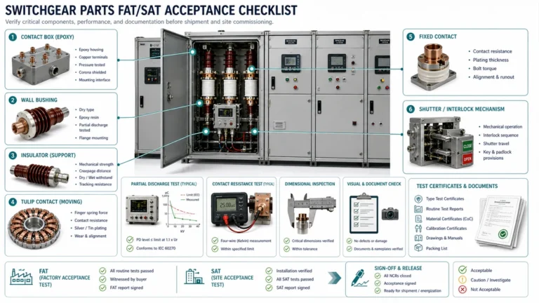
Utilice estas referencias XBRELE para conectar la decisión de campo con el producto correcto, la prueba y el flujo de trabajo de adquisición: Página del producto XBRELE, Gama de disyuntores de vacío XBRELE, Guía de calificaciones del VCB, Lista de comprobación para la aceptación del FAT/SAT de VCB, gama de componentes para aparamenta XBRELE.
Para el contexto del método externo, compare el procedimiento del sitio con el público Página de normas IEEE C37.09 y, a continuación, aplicar el manual exacto del OEM y las especificaciones del proyecto para el equipo suministrado.
Ejemplo práctico: durante una inspección de servicio, una fase midió fuera de su línea de base de puesta en servicio, mientras que las otras dos fases se mantuvieron estables. El equipo repitió la medición con cables verificados, comprobó la temporización y el recorrido de los contactos y utilizó la divergencia medida para separar un problema de presión de contacto de un problema genérico de limpieza de superficies.
El umbral de aceptación más utilizado en la práctica es de 50 microohmios por unión para las conexiones atornilladas de media y alta tensión, tal y como se indica en la sección 7.9 de la norma ANSI/NETA ATS. Sin embargo, se trata de un criterio conservador, no de un objetivo de diseño.
El aluminio sin recubrimiento debe sellarse en un plazo de 10 a 15 minutos tras finalizar el proceso de abrasión mecánica, en condiciones ambientales secas. En entornos con una humedad relativa superior al 70% o con temperaturas superficiales que se desvíen en menos de 3 °C del punto de rocío, este margen de tiempo se reduce aún más.
No. El compuesto inyectado a través de un orificio perforado en el perímetro de la junta tras el atornillado no logra una cobertura uniforme en toda la zona de contacto y no constituye un método de reparación permanente aceptado.
Una medición de resistencia absoluta compara el valor obtenido en la unión con un umbral fijo (por ejemplo, 50 microohmios). La relación de resistencia de la unión (JRR), tal y como se define en la norma NEMA CC 1, compara la resistencia de la unión con la resistencia de un tramo de conductor de igual longitud.
Se recomienda el recubrimiento de plata cuando la temperatura de la superficie de la unión supera habitualmente los 75-80 °C, cuando la instalación se encuentra en una subestación exterior con exposición prolongada a la humedad, o cuando la unión vaya a permanecer en servicio durante largos periodos sin posibilidad de volver a prepararla. El recubrimiento de estaño es adecuado para aparamenta interior seca con una capacidad de corriente moderada.
Como mínimo, el registro de documentación debe incluir la identificación y la ubicación de la unión, el material base y el tipo de recubrimiento confirmados, una lista de comprobación de la preparación debidamente cumplimentada en la que no figure ningún fallo sin resolver, el tiempo transcurrido desde la abrasión hasta el cierre (fundamental en el caso del aluminio), el valor de par registrado para cada posición de perno con confirmación de las marcas de referencia, el modelo y número de serie del instrumento DLRO con el certificado de calibración vigente, la resistencia medida en microohmios y el resultado de «aprobado» o «no aprobado» en relación con el límite de la especificación. Es necesaria la firma del técnico ejecutor, del inspector de control de calidad y del ingeniero supervisor antes de que se archive el registro y se apruebe la unión para su puesta en servicio.