¿Necesita las especificaciones completas?
Descargue nuestro Catálogo de productos 2025 para obtener planos detallados y parámetros técnicos de todos los componentes de los equipos de conmutación.
Obtener catálogo
Descargue nuestro Catálogo de productos 2025 para obtener planos detallados y parámetros técnicos de todos los componentes de los equipos de conmutación.
Obtener catálogo Descargue nuestro Catálogo de productos 2025 para obtener planos detallados y parámetros técnicos de todos los componentes de los equipos de conmutación.
Obtener catálogo
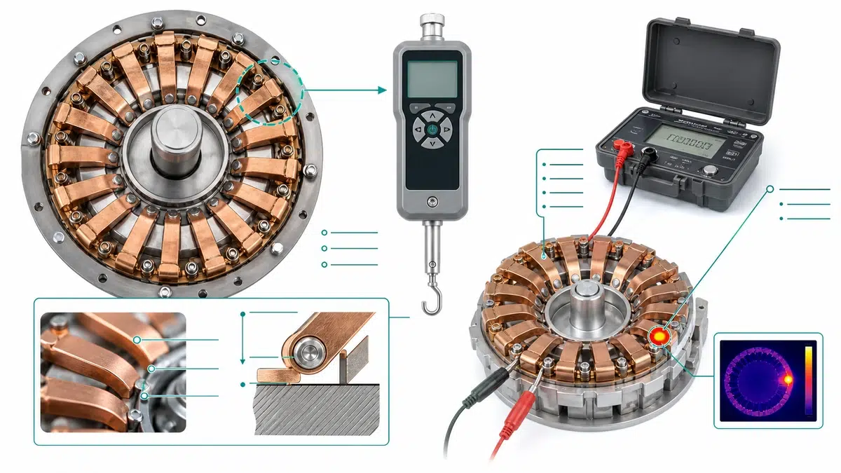
El calentamiento localizado en un conjunto de contactos enchufables o extraíbles es uno de los problemas más comunes y más mal diagnosticados en las instalaciones de conmutación de media y baja tensión. La termografía detecta el síntoma, pero la causa raíz es casi siempre mecánica: la disminución de la fuerza de sujeción del resorte en los dedos de contacto en forma de tulipán. Esta guía abarca todo el proceso de resolución de problemas y mantenimiento, desde el diagnóstico rápido hasta el procedimiento de medición, el análisis de la causa raíz, la programación de inspecciones, la lectura de especificaciones y la adquisición de piezas de recambio.
Antes de realizar una evaluación completa de la fuerza, utiliza esta tabla para confirmar en qué rama de síntomas te encuentras y cuál debería ser la primera prueba.
| Síntoma | Primera prueba | Causa probable | Próxima acción |
|---|---|---|---|
| La cámara térmica muestra un punto caliente solo en una o dos fases | Comprueba el equilibrio de carga en 3%; mide la fuerza del muelle en la fase afectada | La fuerza del resorte está por debajo del mínimo en uno o más dedos | Realizar una medición completa de la fuerza por dedo; sustituirlo si está por debajo del umbral |
| Decoloración o ennegrecimiento por calor en los dedos de contacto | Inspección visual y medidor de fuerza de resorte | Un episodio térmico anterior provocó el recocido; la deformación elástica ha avanzado | Comprobación de la fuerza y medición de la resistencia de contacto (microohmios); tratar ambos |
| Calentamiento uniforme en todas las fases en un mismo lugar | Comprobar la corriente de carga y el contenido armónico | Sobrecarga del sistema o distorsión armónica, no fallo del muelle | Descarta las causas relacionadas con la carga antes de descartar los contactos |
| Zonas problemáticas recurrentes tras la limpieza por contacto | Medidor de la fuerza del muelle tras cada ciclo de mantenimiento | Desgaste de los muelles debido a ciclos previos de sobrecalentamiento | Si la fuerza no se recupera tras la limpieza, sustituye el juego de dedos. |
| Dificultad para insertar o extraer la unidad extraíble | Medidor de fuerza frente al límite superior de fuerza del fabricante original | El exceso de fuerza del muelle provoca desgaste por fricción y rayaduras en el vástago | Comprueba que se respete el límite superior; revisa si la boquilla presenta desgaste |
| No presenta síntomas visibles, pero la antigüedad del conjunto supera los 15 años | Verificación programada de la fuerza del resorte | Relajación por tensión y fatiga relacionadas con la edad | Trátalo como medida preventiva; no te fíes únicamente de las imágenes térmicas |
| Picos de temperatura en momentos de máxima carga; valor de referencia en momentos de carga reducida | Medición de la profundidad de inserción con un medidor de profundidad | Profundidad de inserción insuficiente; área de contacto efectiva reducida bajo carga | Corregir la geometría del mecanismo de inserción; volver a comprobar la profundidad comparándola con el plano del fabricante original |
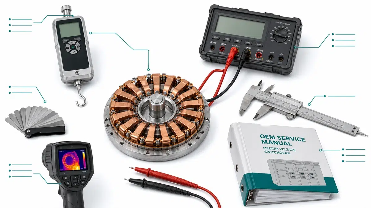
| Instrumento | Propósito | Fuente de aceptación | Especificación mínima |
|---|---|---|---|
| Medidor de fuerza de resorte calibrado (medidor de tracción) | Medir la fuerza radial por dedo | Manual de servicio del fabricante; serie IEC 62271 | Rango: 0-50 N; resolución: ±0,1 N; corriente de calibración |
| Medidor de resistencia de contacto en microohmios | Confirmar la resistencia en la interfaz de contacto | Manual del fabricante; IEEE C37.09 | Resolución de 1 microohmio; corriente de prueba >= 100 A CC |
| Calibres de vernier | Mide el diámetro interior del tulipán y la geometría del dedo | Plano dimensional del fabricante de equipos originales (OEM) | Resolución de 0,02 mm |
| Juego de calibres de espesores | Comprobación adicional del agarre con los dedos | Procedimiento OEM | Intervalo: 0,05-0,5 mm |
| Cámara térmica de infrarrojos | Identificar los conjuntos candidatos para el análisis de fuerzas | Guía sobre termografía de la norma IEC TR 62368 | Sensibilidad <= 0,1 °C; resolución mínima de 320 x 240 |
| Comprobador de resistencia de aislamiento | Comprueba la integridad dieléctrica tras el mantenimiento | Manual del fabricante; IEC 60060 | Salida de 5 kV para equipos de media tensión |
| Profundímetro | Comprueba la profundidad de inserción del conector | Tolerancia del plano de montaje del fabricante de equipos originales (OEM) | Resolución de 0,1 mm |
| Certificados de calibración | Verificar la trazabilidad de los instrumentos | Laboratorio acreditado según la norma ISO/IEC 17025 | Actualizado en los últimos 12 meses |
| Manual de servicio del fabricante original (OEM) | Umbrales de fuerza, criterios de aceptación, valores de par | Fabricante de equipos originales | Revisión específica del equipo |
| Especificaciones del proyecto o norma de mantenimiento | Umbrales de aceptación de emplazamientos | Norma del ingeniero del propietario o de la empresa de servicios públicos | Documento específico del sitio |
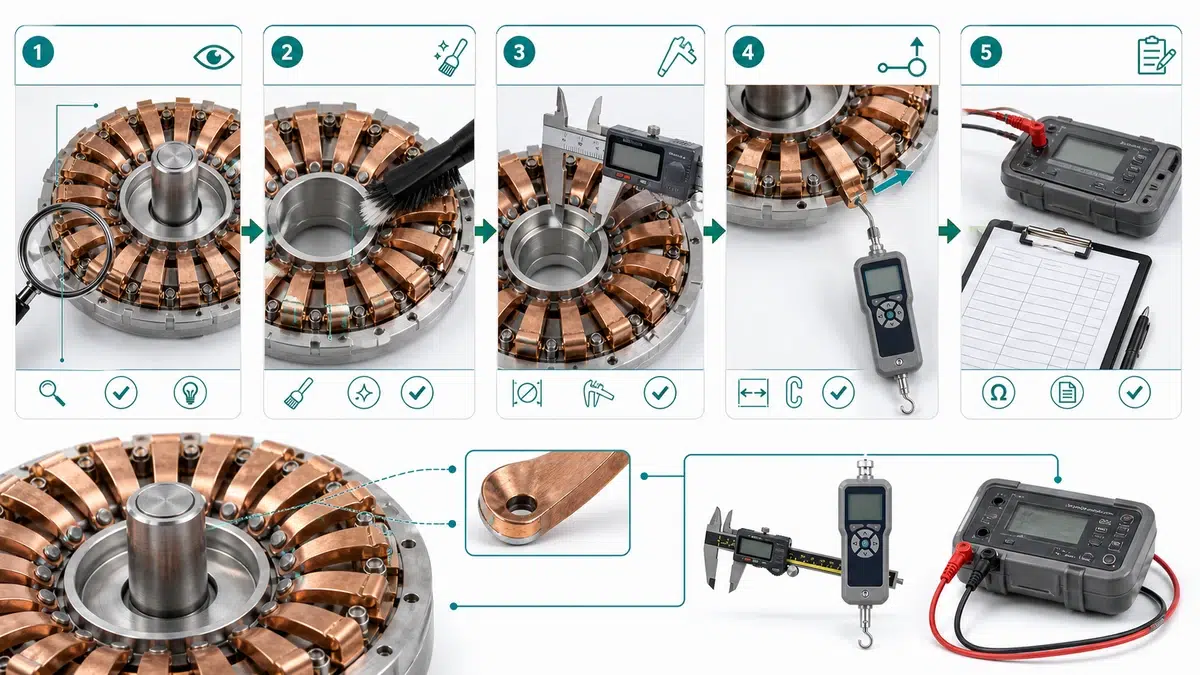
La termografía infrarroja detecta una huella térmica solo cuando la resistencia de contacto ya ha alcanzado un nivel perjudicial. La verificación de la fuerza del resorte de contacto «Tulip» es un indicador adelantado: identifica la reducción de la capacidad de sujeción antes de que las consecuencias térmicas sean visibles o antes de que el aislamiento y los componentes adyacentes sufran daños acumulativos por calor.
Antes de tocar cualquier elemento, se debe completar y verificar la desconexión y el aislamiento mediante el procedimiento de bloqueo y etiquetado de la instalación. Confirme que el mecanismo de enclavamiento esté activado y que se haya descargado la energía acumulada en los mecanismos accionados por resorte.
Paso 1: Revisión visual previa
Paso 2: Limpiar las superficies de contacto
| Parámetro | Pase | Monitor | Rechazar |
|---|---|---|---|
| Fuerza ejercida por cada dedo | >= valor nominal por dedo (normalmente entre 8 y 12 N) | 70-99% del valor nominal | < 70% del valor nominal |
| Fuerza de contacto total | >= 100% de fuerza de montaje nominal | 80-99% de fuerza de montaje nominal | < 80% de fuerza de montaje nominal |
| Dedos no superan el umbral (por debajo del umbral) | 0 | 1 dedo (sustituir el conjunto en la próxima interrupción del suministro) | >= 2 dedos |
| Calibre de espesores con hoja de 0,2 mm | Rechazado por todos los dedos | Se puede colocar la cuchilla con un solo dedo | >= 2 dedos encajan en la hoja |
| Desviación del diámetro interior | <= +0,1 mm de la medida nominal | de +0,1 a +0,3 mm | > +0,3 mm |
| Condición visual | Sin decoloración, sin deformación | Solo una ligera oxidación superficial | Azulamiento por calor, grietas, picaduras o dedos que faltan |
El calentamiento localizado en un conjunto de contactos tipo tulipán rara vez tiene una única causa, pero la pérdida de fuerza del muelle es siempre uno de los primeros factores que hay que descartar o confirmar.
| Fuerza de resorte medida frente al mínimo del fabricante original | Nivel de riesgo térmico | Acción recomendada |
|---|---|---|
| >= 100% de especificaciones mínimas | Bajo | No se requiere ninguna acción inmediata; registrar para analizar la tendencia |
| 90-99% con especificaciones mínimas | Moderado | Aumentar la frecuencia de las inspecciones; planificar la sustitución |
| 75-89% con especificaciones mínimas | Alto | Sustituir en la próxima interrupción programada del suministro; reducir la carga si es posible |
| < 75% de especificaciones mínimas | Crítico | Sustituir antes de volver a ponerlo en servicio |
Síntoma: El escáner de infrarrojos muestra un diferencial de temperatura de 22 °C en el racimo de tulipanes de la fase B en comparación con las fases A y C. Se confirma el equilibrio de carga en 3% en todas las fases.
Medidas: La medición con medidor de fuerza por dedo realizada en el conjunto de la fase B reveló que once de los dieciséis dedos se encontraban por debajo del mínimo establecido por el fabricante original. El valor nominal era de 18 N por dedo; el rango medido fue de 9 a 13 N en los dedos afectados. Se observó una curvatura visible y una longitud libre reducida en comparación con las piezas de repuesto sin usar del mismo lote de producción.
| Mecanismo de degradación | Causa raíz | Efecto cuantificable | Condición acelerada | Medidas correctoras |
|---|---|---|---|---|
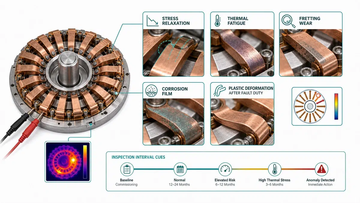
| Relajación de tensiones (fluencia) | La carga estática sostenida supera el límite elástico con el paso del tiempo | Reducción progresiva de la fuerza sin deformación visible | Temperatura ambiente elevada, pala sobredimensionada, tiempo de permanencia prolongado en posición cerrada | Sustituir el juego de muelles; comprobar la tolerancia dimensional de la cuchilla |
| Fatiga térmica | Los ciclos térmicos repetidos provocan la aparición de microfisuras en la base del muelle | Fuerza errática entre estados térmicos; se mide una fuerza menor en caliente que en frío | Alta frecuencia de encendido y apagado diario, sobrecarga continua, ventilación deficiente | Sustituir el juego de muelles; comprobar el equilibrio de corriente entre las fases |
| Deformación plástica (sobrecarga) | Un solo episodio de sobrecarga o una inserción mecánica excesiva bloquea el resorte de forma permanente | Dedos visiblemente separados o doblados; fuerza permanentemente baja | Incidentes de corriente a nivel de fallo, desplazamiento con barra colectora desalineada, geometría de las palas no original del fabricante | Sustituir el juego de muelles; analizar el historial de averías anteriores |
| Corrosión y película superficial | La oxidación o la sulfuración aumentan la resistencia superficial sin alterar la fuerza mecánica. | Calentamiento desproporcionado con respecto a la lectura de fuerza; resistencia de contacto elevada | Alta humedad, ambiente costero o industrial, funcionamiento esporádico | Limpiar las superficies; volver a comprobar la fuerza y la resistencia; sustituir si hay problemas estructurales |
| Fragilización del material de los resortes | Fragilización por hidrógeno o envejecimiento en una aleación de cobre sometida a grandes tensiones | Pérdida repentina de fuerza o rotura del muelle; cambio brusco, no gradual | Antigüedad superior a la vida útil, atmósfera rica en hidrógeno, residuos de recubrimiento | Sustituir el juego de muelles; marcar el lote para la inspección de la flota |
| Desgaste por fricción (pérdida de precarga) | Los micromovimientos entre el asiento del muelle y la carcasa provocan la pérdida de material | Fuerza baja; se observan restos de desgaste en la base del muelle | Entorno con fuertes vibraciones, sujeción de la carcasa poco firme | Comprobar la geometría del asiento; sustituir el juego de muelles y la carcasa si la profundidad del asiento está fuera de tolerancia |
| Montaje incorrecto | El muelle se ha instalado con una orientación incorrecta, en una cantidad incorrecta o sin las herramientas adecuadas | Aplicar una fuerza fuera de las especificaciones inmediatamente después del mantenimiento | Puesta en servicio tras el mantenimiento sin verificación de la fuerza | Vuelva a montarlo utilizando las herramientas originales del fabricante; compruebe la fuerza antes de la puesta en servicio. |
| Estado del campo | Intervalo de referencia (años) | Intervalo ajustado | Mecanismo de riesgo principal |
|---|---|---|---|
| Subestación interior limpia, humedad controlada (< 60% de humedad relativa), con un número mínimo de conmutaciones | 6 | 6 | Solo relajación de la resorte de referencia |
| Entorno costero o con elevada humedad (> 80% de humedad relativa, aire salino) | 6 | 2-3 | La corrosión acelera el ablandamiento de los dedos |
| Entorno industrial con polvo conductor o vapores químicos | 6 | 2 | La contaminación aumenta la carga de fricción; la fuerza del muelle disminuye más rápidamente |
| Alta frecuencia de conmutación (> 200 operaciones al año) | 6 | 2-3 | Fatiga mecánica provocada por la inserción y extracción repetidas |
| Situación tras un evento de fallo total (cualquier magnitud superior a la resistencia nominal) | Inmediato | Inmediato | Las fuerzas electromagnéticas pueden deformar de forma permanente las lengüetas elásticas |
| Instalación expuesta a vibraciones (cerca de maquinaria pesada, zona sísmica) | 6 | 3 | El desgaste por fricción provoca una degradación progresiva del contacto |
| No hay registros de mantenimiento o se desconoce el historial de mantenimiento | Desconocido | Inmediato | La verificación establece un punto de referencia conocido antes de continuar con el funcionamiento |
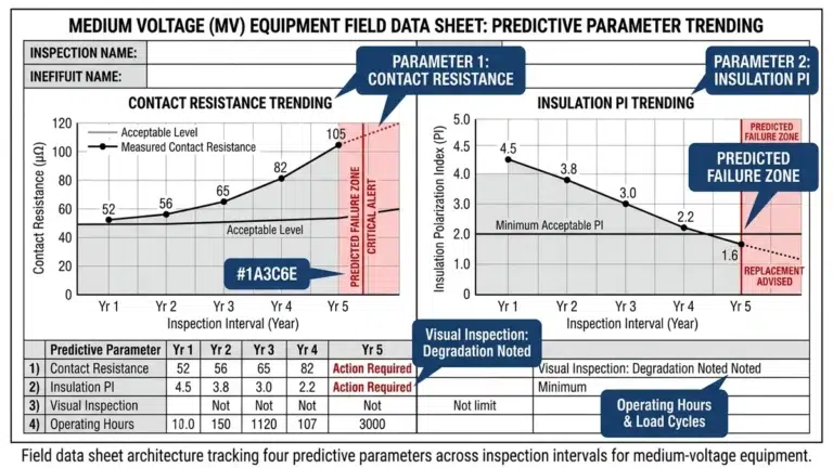
Si la fuerza medida disminuye en más de 5% por ciclo de inspección, acorte el intervalo siguiente en 30-40% en lugar de esperar a que se supere el umbral de fallo. La verificación de la fuerza del muelle también es obligatoria durante la puesta en servicio inicial y tras cualquier mantenimiento interno en el que se desmonten, limpien o lubriquen los dedos.
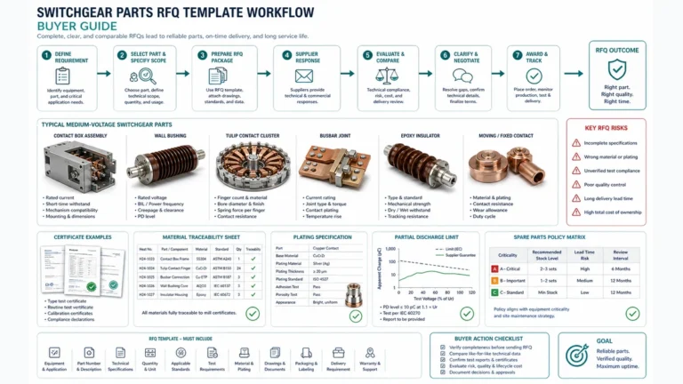
Para pedir un conjunto de muelles de contacto tipo tulipán de recambio, rara vez basta con indicar únicamente el número de modelo del cuadro eléctrico. Los fabricantes modifican la geometría de los muelles, el número de dedos y las especificaciones de precarga a lo largo de las distintas series de producción.
| Artículo que falta | Resultado probable |
|---|---|
| No se indica ninguna tolerancia de fuerza | El proveedor realiza los envíos según los valores nominales del catálogo; la fuerza real puede situarse en el límite de tolerancia. |
| No se ha confirmado el número de dedos | Se ha instalado un conjunto con un número incorrecto de dedos; se ha omitido el recálculo de la fuerza por dedo |
| No se especifica ningún recubrimiento | El recubrimiento sustitutivo ofrece una línea de base diferente para la resistencia de contacto |
| No se han facilitado datos sobre la calefacción | No se ha confirmado la causa principal; es posible que la sustitución no resuelva la anomalía térmica |
| No se solicita certificado de ensayo | No hay forma de comprobar que se cumplan los requisitos de fuerza antes de la instalación |
Identificación del equipo
– Número de referencia del fabricante, incluido el sufijo de revisión
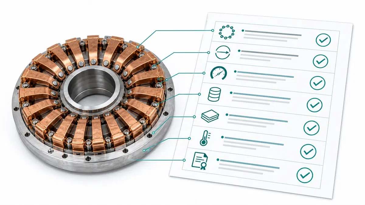
Utilice estas referencias XBRELE para conectar la decisión de campo con el producto correcto, la prueba y el flujo de trabajo de adquisición: Página del producto XBRELE, Gama de disyuntores de vacío XBRELE, Guía de calificaciones del VCB, Lista de comprobación para la aceptación del FAT/SAT de VCB, gama de componentes para aparamenta XBRELE.
Para el contexto del método externo, compare el procedimiento del sitio con el público Página de normas IEEE C37.09 y, a continuación, aplicar el manual exacto del OEM y las especificaciones del proyecto para el equipo suministrado.
Ejemplo práctico: durante una inspección de servicio, una fase midió fuera de su línea de base de puesta en servicio, mientras que las otras dos fases se mantuvieron estables. El equipo repitió la medición con cables verificados, comprobó la temporización y el recorrido de los contactos y utilizó la divergencia medida para separar un problema de presión de contacto de un problema genérico de limpieza de superficies.
La fuerza mínima aceptable la define el fabricante de equipo original (OEM) para cada conjunto específico y se expresa por dedo (normalmente entre 8 y 18 N, dependiendo de la intensidad nominal y la geometría de los contactos) y como total agregado para todo el conjunto. No existe un mínimo universal que se aplique a todos los diseños.
Se aplica un intervalo de referencia de 6 años a las instalaciones interiores limpias con un uso mínimo de los interruptores. Dicho intervalo se reduce a 2-3 años en entornos costeros, de alta humedad o de uso intensivo, y a una verificación inmediata tras cualquier evento de fallo de paso, tras cualquier mantenimiento interno del conjunto de contactos y durante la puesta en servicio inicial.
Sí. Un solo dedo que no aporte ninguna fuerza de sujeción útil concentra la corriente a través de los dedos adyacentes, lo que aumenta la densidad de corriente local y el calentamiento por I²R en esos puntos de contacto.
No. La sustitución de dedos individuales dentro de un conjunto ya existente provoca una discrepancia en la rigidez de los resortes entre los dedos nuevos y los desgastados, lo que redistribuye la presión de contacto de forma no uniforme.
La relajación por tensión es una reducción gradual y dependiente del tiempo de la fuerza de sujeción a una deformación constante: el muelle conserva su forma, pero ejerce una fuerza cada vez menor a lo largo de meses o años, especialmente a temperaturas elevadas. La deformación plástica es un cambio inmediato y permanente en la geometría del resorte provocado por un único episodio de sobrecarga, como una corriente de fallo o una inserción mecánica excesiva, y produce una curvatura o un ensanchamiento visible del dedo.
Una profundidad de inserción insuficiente desplaza la presión de contacto hacia las puntas de los dedos, en lugar de hacia la zona de contacto central prevista en el diseño, lo que reduce el área de contacto efectiva, aunque cada dedo genere su fuerza de sujeción nominal. Esto produce un calentamiento que, en un escáner térmico, resulta indistinguible de la degradación de la fuerza del muelle; por ello, la profundidad de inserción debe verificarse independientemente de la fuerza del muelle durante cada análisis de contacto.
La norma IEC 62271-100 establece los requisitos de rendimiento para los interruptores automáticos de CA, incluidas las especificaciones de los contactos, mientras que la norma IEC 62271-200 se refiere a los equipos de conmutación y control en envolventes metálicas. En las aplicaciones de América del Norte se aplican las normas de la serie ANSI/IEEE C37.