Нужны полные технические характеристики?
Загрузите наш каталог продукции 2025 года, чтобы ознакомиться с подробными чертежами и техническими параметрами всех компонентов распределительного устройства.
Получить каталог
Загрузите наш каталог продукции 2025 года, чтобы ознакомиться с подробными чертежами и техническими параметрами всех компонентов распределительного устройства.
Получить каталог Загрузите наш каталог продукции 2025 года, чтобы ознакомиться с подробными чертежами и техническими параметрами всех компонентов распределительного устройства.
Получить каталог
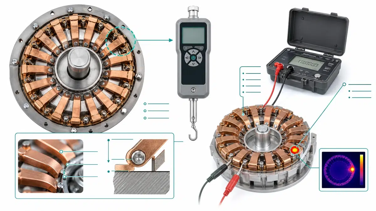
Локальный нагрев в разъемном или выдвижном контактном узле — одна из наиболее распространенных и часто неправильно диагностируемых неисправностей в распределительных устройствах среднего и низкого напряжения. Тепловизионное обследование позволяет выявить этот симптом, однако первопричина почти всегда носит механический характер: снижение усилие зажима пружины на контактных пальцах типа «тюльпан». В данном руководстве подробно описан полный процесс устранения неисправностей и технического обслуживания — от быстрой диагностики до процедуры измерений, анализа первопричин, планирования проверок, изучения технических характеристик и закупки запасных частей.
Прежде чем приступить к полноценному измерению силы, воспользуйтесь этой таблицей, чтобы определить, в какой ветви симптомов вы находитесь и каким должен быть первый тест.
| Симптом | Первое испытание | Вероятная первопричина | Следующее действие |
|---|---|---|---|
| Тепловизионная камера показывает горячую точку только на одной или двух фазах | Проверить распределение нагрузки в пределах 3%; измерить усилие пружины на затронутой фазе | Усилие пружины ниже минимального значения на одном или нескольких пальцах | Провести полное измерение силы на каждый палец; заменить, если показатель ниже порогового значения |
| Изменение цвета или появление синего налета на контактных контактах под воздействием тепла | Визуальный осмотр и измерение усилия пружины | Предыдущее тепловое воздействие привело к отжигу; деформация пружины усилилась | Проверка усилия и измерение контактного сопротивления (в микроомах); выполнить обе операции |
| Равномерный нагрев всех фаз в одной и той же точке | Проверить ток нагрузки и содержание гармоник | Перегрузка системы или гармонические искажения, а не поломка пружины | Прежде чем признавать контакты неисправными, исключите причины, связанные со стороной нагрузки |
| Периодическое появление «горячих точек» после очистки контактов | Проверка усилие пружины после каждого цикла технического обслуживания | Весенняя усталость материала, вызванная предыдущими циклами перегрева | Если после очистки усилие не восстанавливается, замените набор пальцев |
| Трудности при вставке или извлечении съемного блока | Силоизмеритель при предельном значении верхнего предела усилия, установленном производителем оборудования (OEM) | Избыточное усилие пружины, вызывающее износ от трения и появление царапин на втулке | Убедитесь в соответствии верхнего предела; проверьте патрубок на износ |
| Видимых симптомов нет, но срок эксплуатации агрегата превышает 15 лет | Плановая проверка усилие пружины | Возрастное релаксирование напряжений и усталость | Используйте в профилактических целях; не полагайтесь исключительно на тепловизионное обследование |
| Всплески температуры при пиковой нагрузке, базовый уровень при малой нагрузке | Измерение глубины посадки с помощью глубиномера | Недостаточная глубина вставки; уменьшение эффективной площади контакта под нагрузкой | Исправить геометрию механизма ввода стойки; повторно проверить глубину в соответствии с чертежом оригинального производителя |
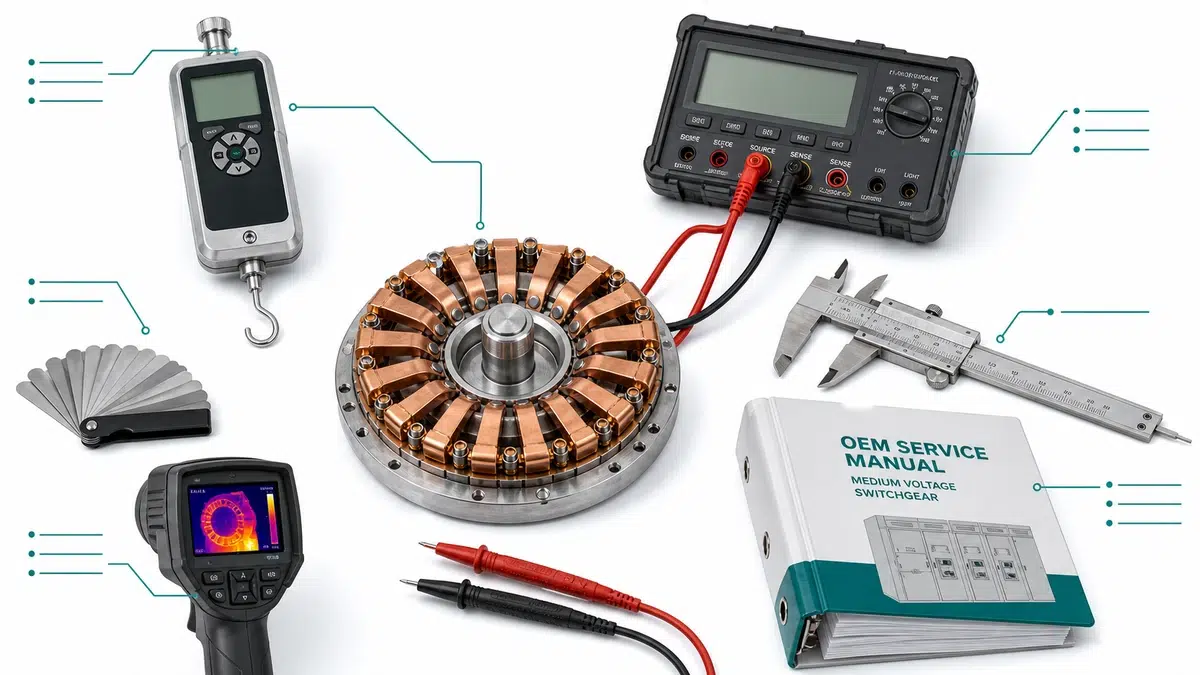
| Инструмент | Цель | Источник акцепта | Минимальная спецификация |
|---|---|---|---|
| Калиброванный измеритель усилие пружины (измеритель тяги) | Измерить радиальную силу, действующую на каждый палец | Руководство по техническому обслуживанию от производителя; серия стандартов IEC 62271 | Диапазон 0–50 Н; разрешение ±0,1 Н; калибровочный ток |
| Тестер контактного сопротивления в микроомах | Подтвердить наличие сопротивления на границе раздела | Руководство производителя; IEEE C37.09 | Разрешение 1 микроом; испытательный ток ≥ 100 А постоянного тока |
| Шкипельные штангенциркули | Измерить диаметр отверстия тюльпана и геометрию пальца | Размерный чертеж OEM | Разрешение 0,02 мм |
| Набор щупов | Дополнительная проверка зацепления пальцев | Процедура OEM | Диапазон 0,05–0,5 мм |
| Инфракрасная тепловизионная камера | Определить сборки, подходящие для исследования под действием силы | Руководство по термографии IEC TR 62368 | Чувствительность <= 0,1 °C; минимальное разрешение 320 × 240 |
| Тестер сопротивления изоляции | После проведения технического обслуживания проверьте целостность диэлектрика | Руководство производителя; IEC 60060 | Выходное напряжение 5 кВ для оборудования среднего напряжения |
| Глубиномер | Проверьте глубину вставки штекера | Допуски на сборочных чертежах OEM | Разрешение 0,1 мм |
| Сертификаты калибровки | Проверить прослеживаемость приборов | Лаборатория, аккредитованная по стандарту ISO/IEC 17025 | Текущие за последние 12 месяцев |
| Руководство по техническому обслуживанию от производителя | Предельные значения силы, критерии приемки, значения крутящего момента | Производитель оригинального оборудования | Версия для конкретного оборудования |
| Техническое задание проекта или стандарт технического обслуживания | Пороговые значения приемлемости объекта | Стандарт, разработанный инженером-заказчиком, или стандарт энергоснабжающей организации | Документ, относящийся к конкретному объекту |
Инфракрасная термография фиксирует тепловой след только после того, как контактное сопротивление уже возросло до уровня, способного привести к повреждению. Проверка усилие контактной пружины Tulip является опережающим показателем: она позволяет выявить снижение зажимной способности до того, как станут заметны тепловые последствия, или до того, как изоляция и соседние компоненты получат накопительные тепловые повреждения.
Перед любым контактом с оборудованием необходимо завершить и проверить отключение питания и изоляцию в соответствии с процедурой блокировки и маркировки объекта. Убедитесь, что механизм блокировки включен и что накопленная энергия в пружинных механизмах разряжена.
Шаг 1 — Визуальная предварительная проверка
Шаг 2 — Очистка контактных поверхностей
| Параметр | Пропуск | Монитор | Отклонить |
|---|---|---|---|
| Усилие отдельного пальца | >= номинальное значение на палец (обычно 8–12 Н) | 70-99% номинального значения | < 70% от номинального значения |
| Суммарная сила контакта | >= 100% номинального усилия сборки | 80–99% номинального усилия затяжки | < 80% номинального усилия сборки |
| Неудачные попытки (ниже порогового значения) | 0 | 1 палец (заменить комплект при следующем отключении) | >= 2 пальца |
| Щуп с лезвием толщиной 0,2 мм | Отвергнуто всеми пальцами | 1 паз для лезвия | >= 2 пальца удерживают лезвие |
| Отклонение диаметра отверстия | <= +0,1 мм от номинального значения | от +0,1 до +0,3 мм | > +0,3 мм |
| Состояние зрения | Без изменения цвета, без деформации | Лишь легкое окисление поверхности | Термическое синение, трещины, точечная коррозия или отсутствующие пальцы |
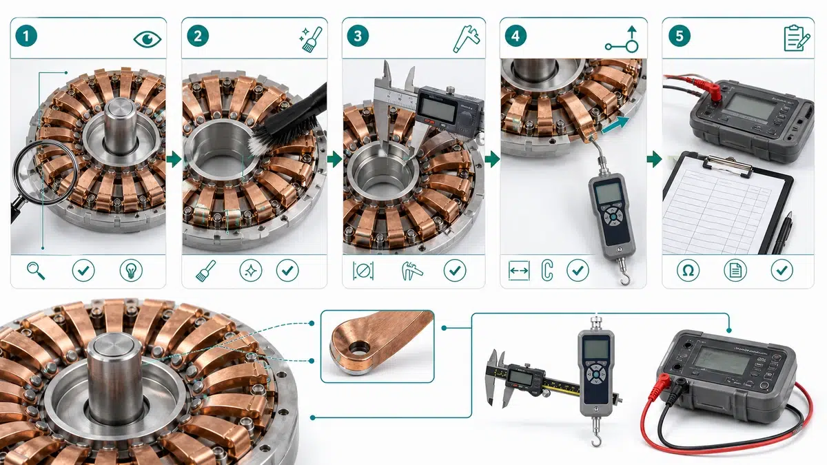
Локальный нагрев в узле «тюльпанного» контакта редко имеет одну единственную причину, однако снижение усилие пружины неизменно является одним из первых вариантов, которые следует исключить или подтвердить.
| Измеренное усилие пружины по сравнению с минимальным значением, указанным производителем | Уровень теплового риска | Рекомендуемые действия |
|---|---|---|
| >= 100% с минимальными техническими характеристиками | Низкий | Не требуется немедленных действий; зафиксировать для отслеживания динамики |
| 90-99% с минимальными техническими характеристиками | Умеренный | Увеличить частоту проверок; запланировать замену |
| 75-89% с минимальными техническими характеристиками | Высокий | Заменить во время следующего планового отключения; по возможности снизить нагрузку |
| < 75% по минимальным техническим характеристикам | Критический | Замените перед возвращением в эксплуатацию |
Симптом: Инфракрасное сканирование показывает разницу температур в 22 °C в кластере тюльпанов фазы B по сравнению с фазами A и C. Подтверждено равномерное распределение нагрузки в пределах 3% по всем фазам.
Размеры: Измерение усилия на каждом пальце кластера B-фазы показало, что у одиннадцати из шестнадцати пальцев значение было ниже минимального значения, установленного производителем. Номинальное значение составляло 18 Н на палец; диапазон измеренных значений для соответствующих пальцев составил 9–13 Н. Были отмечены видимое искривление и уменьшение свободной длины по сравнению с неиспользованными запасными частями из той же производственной партии.
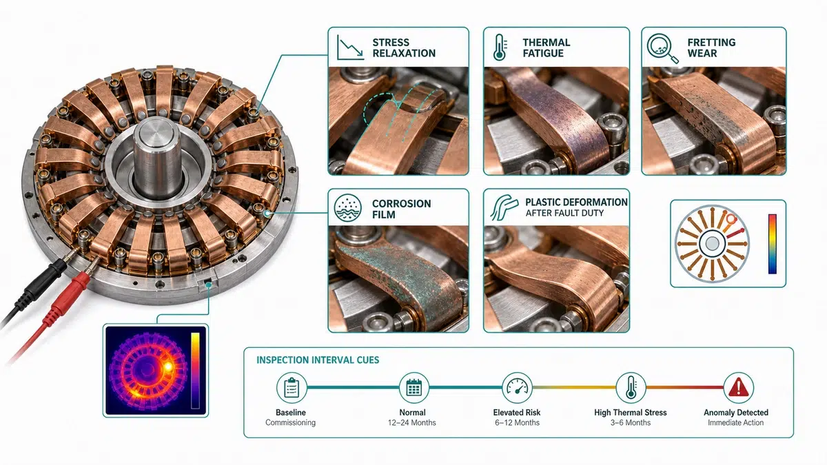
| Механизм разложения | Основная причина | Измеримый эффект | Ускоряющееся состояние | Корректирующие действия |
|---|---|---|---|---|
| Релаксация напряжений (ползучесть) | Длительная статическая нагрузка со временем превышает предел упругости | Постепенное снижение усилия без видимой деформации | Высокая температура окружающей среды, лопасть увеличенного размера, длительное нахождение в закрытом положении | Заменить комплект пружин; проверить допуски на размеры лезвия |
| Термическая усталость | Повторные термоциклы приводят к образованию микротрещин у основания пружины | Неравномерное взаимодействие между тепловыми состояниями; при высоких температурах сила взаимодействия меньше, чем при низких | Высокая частота включений и выключений в течение суток, постоянная перегрузка, плохая вентиляция | Замените комплект пружин; проверьте баланс тока между фазами |
| Пластическая деформация (превышение предела прочности) | Однократное перегрузочное воздействие или механическое введение на избыточную глубину приводит к необратимому закреплению пружины | Заметное расширение или искривление пальцев; сила постоянно низкая | События, связанные с током на уровне неисправности, установка в стойку с несоосностью шины, геометрия лопастей, не соответствующая спецификациям производителя | Заменить комплект пружин; проанализировать записи о неисправностях, произошедших ранее |
| Коррозия и поверхностная пленка | Окисление или сульфидирование приводит к увеличению поверхностного сопротивления без изменения механической силы | Нагрев, несоразмерный показаниям силы; повышенное сопротивление контакта | Высокая влажность, прибрежная или промышленная среда, нечастая эксплуатация | Очистите поверхности; повторно проверьте усилие и сопротивление; замените, если это касается конструкции |
| Весеннее охрупчивание материала | Водородное охрупчивание или старение в медном сплаве, подвергаемом высоким нагрузкам | Внезапная потеря усилие или разрыв пружины; скачкообразное изменение, а не постепенное | Превышение срока службы, атмосфера с высоким содержанием водорода, остатки гальванического покрытия | Заменить комплект пружин; отметить партию для проверки автопарка |
| Износ от трения (потеря предварительной нагрузки) | Микроперемещения между опорой пружины и корпусом приводят к потере материала | Напряжение низкое; на основании пружины виден износ | Среда с высоким уровнем вибрации, ненадёжная фиксация корпуса | Проверить геометрию седла; заменить комплект пружин и корпус, если глубина седла выходит за пределы допуска |
| Неправильная сборка | Пружина установлена в неправильном положении, в неправильном количестве или без использования соответствующего инструмента | Принудительное отключение в случае выхода за пределы технических характеристик сразу после технического обслуживания | Ввод в эксплуатацию после технического обслуживания без проверки усилие | Соберите устройство с использованием оригинального инструмента; перед подачей напряжения проведите проверку усилие |
| Состояние поля | Базовый интервал (годы) | Скорректированный интервал | Основной механизм риска |
|---|---|---|---|
| Чистая внутренняя подстанция, контролируемая влажность (< 60% относительной влажности), минимальное количество коммутационных операций | 6 | 6 | Только исходная пружинная релаксация |
| Прибрежная среда или среда с высокой влажностью (> 80% относительной влажности, соленый воздух) | 6 | 2-3 | Коррозия ускоряет размягчение пальцев |
| Промышленная среда с наличием проводящей пыли или химических паров | 6 | 2 | Загрязнение увеличивает нагрузку трения; усилие пружины снижается быстрее |
| Высокая интенсивность переключений (> 200 циклов в год) | 6 | 2-3 | Механическая усталость, вызванная многократным вставлением и извлечением |
| Состояние после пробоя (любая величина, превышающая номинальную выдерживаемую мощность) | Срочно | Срочно | Электромагнитные силы могут привести к необратимой деформации пружинных пальцев |
| Установка в условиях повышенной вибрации (вблизи тяжелого оборудования, в сейсмической зоне) | 6 | 3 | Износ от трения приводит к постепенному ухудшению контактных характеристик |
| Отсутствуют записи о техническом обслуживании или история обслуживания неизвестна | Неизвестно | Срочно | В ходе проверки устанавливается исходное состояние перед продолжением работы |
Если измеренное усилие снижается более чем на 5% за один цикл проверки, следует сократить следующий интервал на 30–40%, а не дожидаться превышения порогового значения отказа. Проверка усилие пружины также обязательна при первоначальном вводе в эксплуатацию и после любого внутреннего технического обслуживания, в ходе которого пальцы снимаются, очищаются или смазываются.
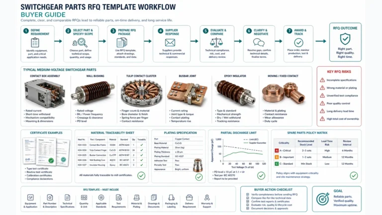
Для заказа запасного узла контактной пружины типа «тюльпан» одного только номера модели распределительного устройства, как правило, недостаточно. Производители в ходе различных серий производства вносят изменения в геометрию пружины, количество контактов и параметры предварительной нагрузки.
| Отсутствующий товар | Вероятный исход |
|---|---|
| Допуск по усилию не указан | Поставщик поставляет продукцию в соответствии с номинальными значениями, указанными в каталоге; фактическое усилие может находиться на пределе допуска |
| Количество пальцев не подтверждено | Установлена сборка с неверным количеством пальцев; пересчет силы на каждый палец пропущен |
| Покрытие не указано | Метод замещающего гальванического покрытия обеспечивает иную базовую линию сопротивления контакта |
| Данные об отоплении не предоставлены | Основная причина не подтверждена; замена может не устранить тепловую аномалию |
| Сертификат испытаний не требуется | Нет возможности проверить соответствие усилию перед установкой |
Идентификация оборудования
– Номер детали OEM с суффиксом версии
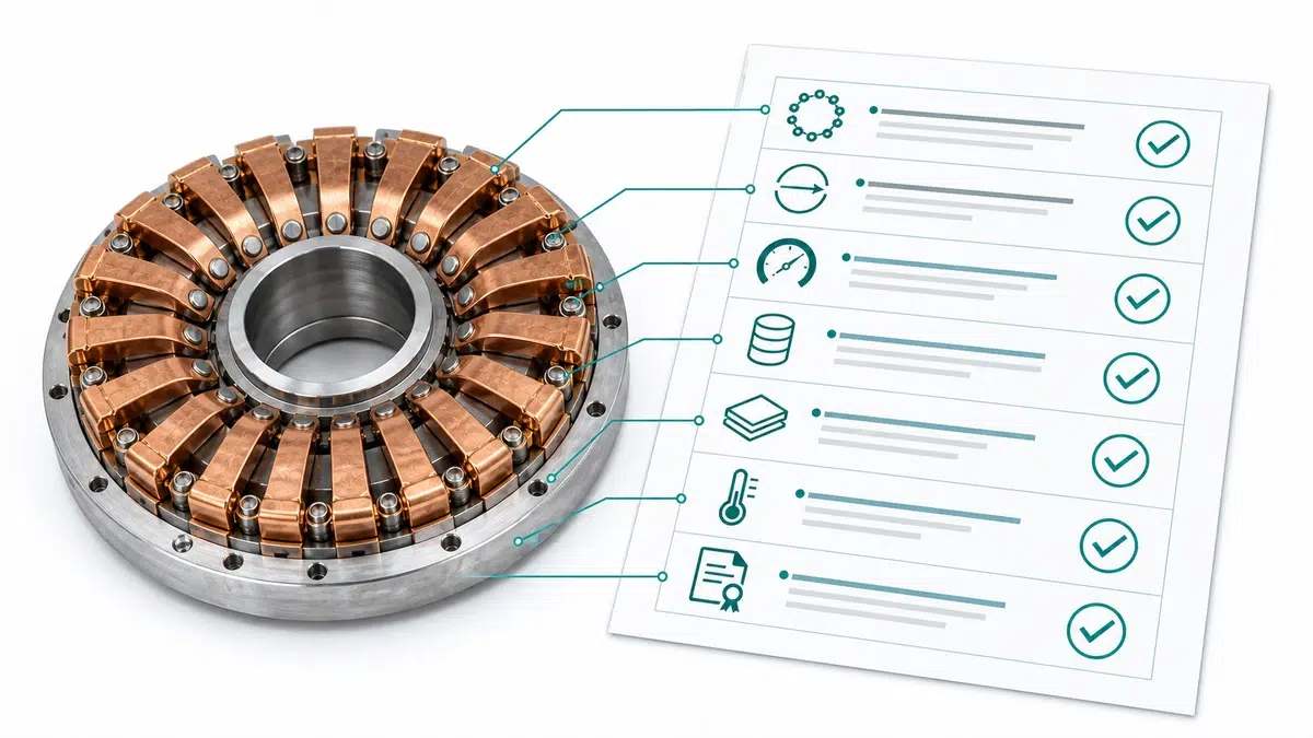
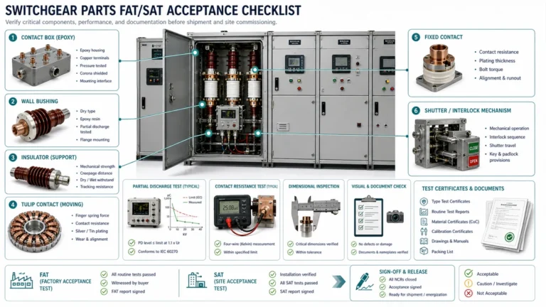
Используйте эти ссылки XBRELE, чтобы связать решение, принятое на месте, с правильным процессом производства, испытаний и закупок: Страница продукта XBRELE, Ассортимент вакуумных выключателей XBRELE, Руководство по рейтингам VCB, Контрольный список для сдачи экзамена VCB FAT/SAT, ассортимент деталей для распределительных устройств XBRELE.
Для внешнего контекста метода сравните процедуру сайта с публичной Страница стандартов IEEE C37.09 и затем применить точное руководство производителя и спецификацию проекта для поставляемого оборудования.
Пример из практики: во время сервисной проверки одна фаза измерялась вне базовой линии ввода в эксплуатацию, в то время как две другие фазы оставались стабильными. Команда повторила измерение с проверенными выводами, проверила время и ход контактов и использовала измеренное расхождение, чтобы отделить проблему контактного давления от общей проблемы очистки поверхности.
Минимальное допустимое усилие определяется производителем оригинального оборудования (OEM) для каждой конкретной сборки и указывается как значение на один контакт (обычно 8–18 Н в зависимости от номинального тока и геометрии контактов), а также в виде совокупного значения для всего блока. Универсального минимального значения, применимого ко всем конструкциям, не существует.
Базовый интервал в 6 лет применяется к чистым установкам в помещениях с минимальной частотой включения-выключения. Этот интервал сокращается до 2–3 лет в прибрежных условиях, в условиях высокой влажности или при интенсивной эксплуатации, а также требует немедленной проверки после любого случая сквозного замыкания, после любого внутреннего технического обслуживания контактного узла и при первоначальном вводе в эксплуатацию.
Да. Один палец, не оказывающий полезного зажимного усилия, концентрирует ток через соседние пальцы, что приводит к повышению локальной плотности тока и нагреву по формуле I²R в этих точках соприкосновения.
Нет. Замена отдельных пальцев в существующем блоке приводит к несоответствию жесткости пружин между новыми и изношенными пальцами, что вызывает неравномерное перераспределение контактного давления.
Релаксация напряжений — это постепенное, зависящее от времени снижение удерживающего усилия при постоянной деформации: пружина сохраняет свою форму, но в течение месяцев или лет оказывает всё меньшее усилие, особенно при повышенной температуре. Пластическая деформация — это мгновенное, необратимое изменение геометрии пружины, вызванное единичным перегрузочным воздействием, таким как ток замыкания на землю или механическое переуглубление, и приводящее к видимому изгибу или расширению «пальца».
Недостаточная глубина вставки приводит к переносу контактного давления на кончики пальцев, а не на предусмотренную конструкцией зону контакта в средней части, что уменьшает эффективную площадь контакта, даже если каждый палец создает номинальное усилие зажима. Это вызывает нагрев, который на тепловизионном скане невозможно отличить от снижения усилие пружины, поэтому при каждой проверке контактов глубину вставки необходимо проверять независимо от усилия пружины.
Стандарт IEC 62271-100 устанавливает эксплуатационные требования к автоматическим выключателям переменного тока, включая технические характеристики контактов, а стандарт IEC 62271-200 посвящен распределительным и управляющим устройствам в металлическом корпусе. В Северной Америке применяются стандарты серии ANSI/IEEE C37.