Hai bisogno delle specifiche complete?
Scarica il nostro Catalogo prodotti 2025 per disegni dettagliati e parametri tecnici di tutti i componenti dei quadri elettrici.
Richiedi il catalogoScarica il nostro Catalogo prodotti 2025 per disegni dettagliati e parametri tecnici di tutti i componenti dei quadri elettrici.
Richiedi il catalogoScarica il nostro Catalogo prodotti 2025 per disegni dettagliati e parametri tecnici di tutti i componenti dei quadri elettrici.
Richiedi il catalogo
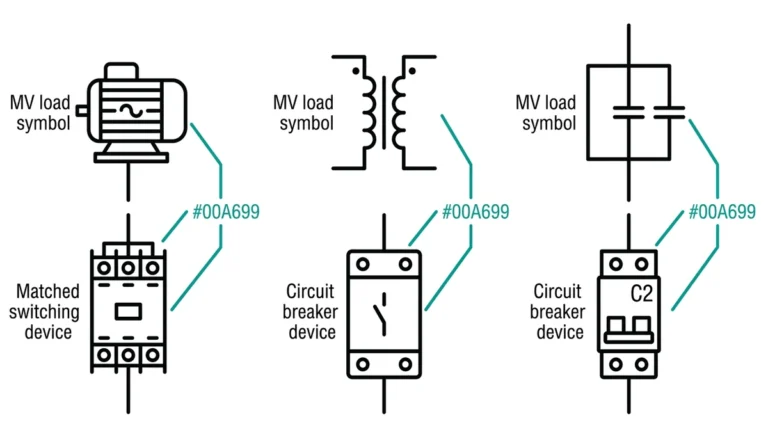
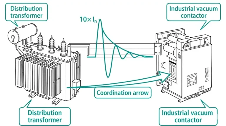
Pianificare il retrofit di un contattore aria-vuoto con controlli per l'adattamento, i valori nominali, il cablaggio di controllo, la protezione dalle sovratensioni e la messa in servizio.
Il passaggio dai contattori ad aria ai contattori sottovuoto rappresenta uno degli aggiornamenti più significativi disponibili per i centri di controllo motore a media tensione e le installazioni di quadri elettrici. Dopo aver trascorso quasi due decenni nella messa in servizio e nella ricerca guasti di questi retrofit in impianti petrolchimici, impianti di trattamento delle acque e attività produttive, posso affermare con certezza che questo aggiornamento offre notevoli vantaggi operativi, ma solo se eseguito con un'attenzione meticolosa alla compatibilità, alle modifiche dei circuiti di controllo e alle procedure di messa in servizio corrette.
I contattori d'aria, pur essendo stati affidabili nel loro tempo, presentano sfide crescenti per le strutture moderne. I requisiti di manutenzione più elevati, gli ingombri fisici maggiori e le capacità di interruzione limitate li rendono candidati alla sostituzione, soprattutto nelle installazioni risalenti agli anni '70 e '90. I contattori sottovuoto offrono un'interruzione dell'arco superiore, intervalli di manutenzione drasticamente ridotti e una maggiore sicurezza operativa.
Questo articolo fornisce una tabella di marcia tecnica dettagliata per gli ingegneri, i professionisti della manutenzione e i responsabili di progetto che intraprendono il retrofit dei contattori aria-vapore. Attingendo all'esperienza di progetti reali e alle pratiche consolidate del settore, esamineremo ogni aspetto critico di questo processo di aggiornamento.
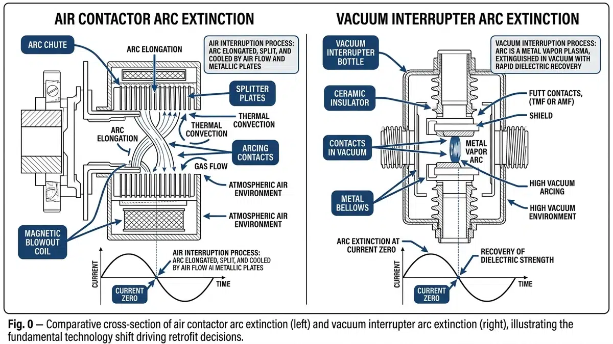
I contattori ad aria si basano su scivoli ad arco con piastre divisorie multiple per raffreddare e allungare l'arco durante la separazione dei contatti. L'arco si spegne quando la corrente passa a zero, ma il processo genera notevoli gas ionizzati ed erosione dei contatti. Questo meccanismo limita i contattori ad aria a circa 50.000 operazioni prima di richiedere una manutenzione importante.
I contattori sotto vuoto funzionano secondo un principio completamente diverso. I contatti si separano all'interno di un'interruzione sigillata sotto vuoto (tipicamente da 10-⁶ a 10-⁸ torr), dove l'assenza di mezzo ionizzante causa una rapida estinzione dell'arco, spesso entro mezzo ciclo. La durata dei contatti può raggiungere 1-2 milioni di operazioni meccaniche e oltre 100.000 operazioni elettriche alla corrente nominale.
| Parametro | Contattore aria | Contattore a vuoto |
|---|---|---|
| Durata dell'arco | 8-15 ms | 2-4 ms |
| Erosione da contatto per operazione | 0,1-0,3 mm³ | 0,001-0,01 mm³ |
| Recupero dielettrico | Graduale | Quasi istantaneo |
| Corrente di taglio | 5-15 A | 3-8 A (design moderno) |
| Probabilità di restrike | Basso | Molto basso |
La minore durata dell'arco dei contattori sotto vuoto comporta una minore energia di dispersione durante l'interruzione, ma crea anche un taglio di corrente più rapido che può generare transitori di tensione, un aspetto critico che affronteremo nella sezione dedicata alle modifiche di controllo.
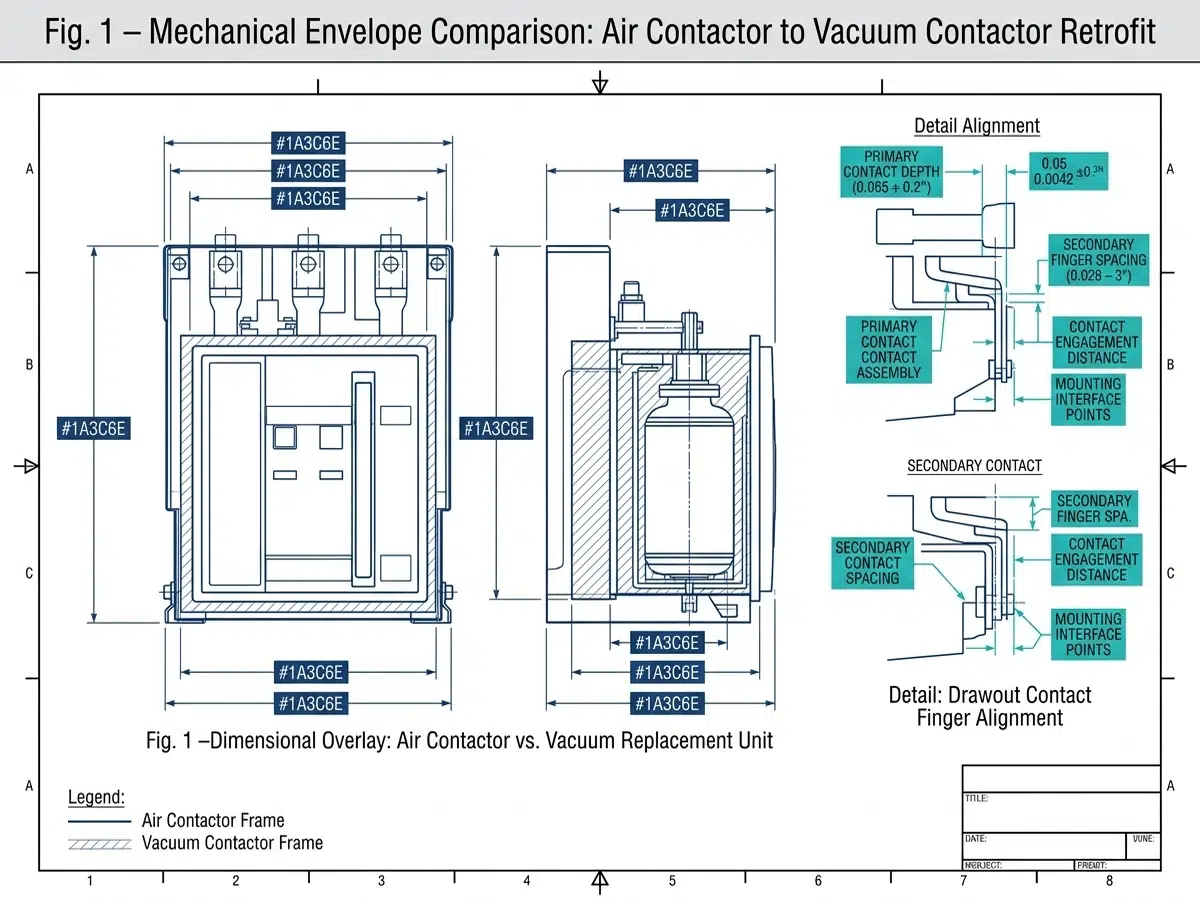
Prima di ordinare un'apparecchiatura sostitutiva, è necessario effettuare un'accurata analisi dimensionale dell'installazione esistente. I moderni contattori sottovuoto sono in genere più compatti delle loro controparti pneumatiche, ma le configurazioni di montaggio variano significativamente tra i vari produttori.
Le misure critiche includono:
– Spazio libero verticale: I contattori sotto vuoto hanno spesso requisiti di altezza diversi a causa della soppressione integrale delle sovratensioni o dei moduli elettronici della bobina.
– Schema dei fori di montaggio: Raramente identici; di solito sono necessarie piastre di adattamento.
– Spaziatura di fase: Deve corrispondere alle configurazioni bus esistenti o richiedere modifiche al bus.
– Spazio per la porta: Alcuni contattori a vuoto sono dotati di meccanismi di azionamento a proiezione frontale.
Durante un recente retrofit in una raffineria della Costa del Golfo, abbiamo scoperto che i contattori sottovuoto sostitutivi richiedevano 3 pollici di spazio aggiuntivo in profondità a causa dei blocchi di contatti ausiliari montati posteriormente. Ciò ha richiesto lo spostamento delle morsettiere e l'estensione del cablaggio di controllo, una modifica che ha aggiunto due giorni al programma del progetto.
La compatibilità dei valori nominali va oltre la semplice corrispondenza tra tensione e corrente:
I moderni contattori sotto vuoto incorporano spesso moduli di controllo elettronici che differiscono fondamentalmente dalle bobine elettromagnetiche dei contattori ad aria. Questi moduli richiedono in genere:
- Alimentatori CC o CA puliti
- Larghezze d'impulso minime specifiche per un funzionamento affidabile
- Diverse sequenze di temporizzazione dei contatti ausiliari
- Verifica della compatibilità con la logica di PLC o relè esistente
Le bobine dei contattori pneumatici tradizionali assorbono una notevole corrente di spunto (spesso 8-10 volte la corrente di tenuta) seguita da una corrente di mantenimento costante. La bobina stessa offre una resistenza intrinseca alle variazioni del circuito di controllo. Le bobine elettroniche dei contattori sotto vuoto funzionano in modo diverso:
Durante l'installazione, verificare che le fonti di alimentazione di controllo siano in grado di fornire una corrente adeguata durante il funzionamento simultaneo di più contattori, una situazione comune durante i trasferimenti del bus del motore.
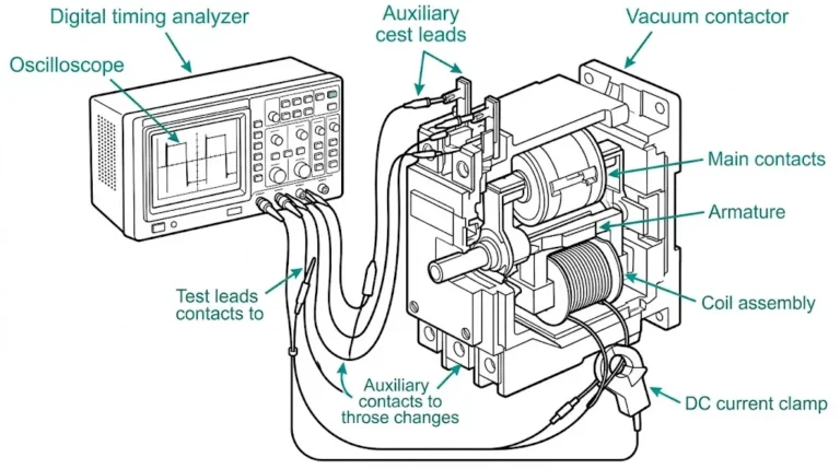
I contattori ad aria hanno in genere blocchi di contatti ausiliari dedicati con temporizzazione fissa rispetto al funzionamento del contatto principale. I contattori sotto vuoto offrono una maggiore flessibilità, ma richiedono un'attenta configurazione:
Contatti di prealimentazione deve chiudersi prima dei contatti del vuoto principale per consentire l'attivazione dei circuiti di protezione dalle sovratensioni. Contatti a tenuta stagna possono richiedere regolazioni della tempistica per tenere conto dei diversi tempi di funzionamento. Contatti di feedback sullo stato necessità di verificare l'adeguata capacità di trasporto della corrente per i carichi collegati.
Si consiglia di creare un documento dettagliato di mappatura dei contatti ausiliari che confronti le funzioni esistenti con le capacità del contattore sostitutivo prima di iniziare l'installazione fisica.
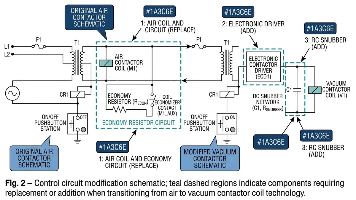
Le caratteristiche di commutazione rapida dei contattori sotto vuoto possono generare transitori di tensione quando si interrompono le correnti del motore. Questi transitori, causati da fenomeni di taglio della corrente e di taglio virtuale della corrente, possono sollecitare l'isolamento del motore e causare interferenze nel sistema di controllo.
La protezione contro le sovratensioni richiesta comprende in genere:
- Snubber RC (reti di resistenze-capacitori) su ogni fase
- Varistori in ossido di metallo (MOV) adatti ai requisiti di tensione e assorbimento di energia del sistema
- Condensatori di sovratensione per motori con sistemi di isolamento aggiornati
Per i motori costruiti prima della fine degli anni '90, che possono avere livelli di isolamento di base ad impulsi (BIL) più bassi, la protezione dalle sovratensioni è obbligatoria. Calcolare i requisiti energetici in base all'induttanza del motore e ai livelli di corrente di taglio.
Togliere la tensione e bloccare/etichettare tutte le fonti di alimentazione, compresi i circuiti di controllo e i trasformatori di potenziale. Verificare lo stato di energia zero utilizzando un'apparecchiatura di prova adeguatamente dimensionata.
Documentate tutti i collegamenti elettrici esistenti con fotografie ed etichette dettagliate prima di scollegarli. Questa documentazione si rivela preziosa durante la risoluzione dei problemi di messa in servizio e crea registrazioni permanenti per i sistemi di documentazione dell'impianto.
Rimuovere prima i gruppi di scivoli ad arco, poi i dispositivi ausiliari e infine il ritiro del contattore principale. Ispezionare le boccole delle celle e le sbarre per rilevare eventuali segni di surriscaldamento o danni che devono essere risolti prima di installare nuove apparecchiature.
La maggior parte dei retrofit richiede piastre di adattamento personalizzate per adattarsi agli schemi dei fori di montaggio. Queste piastre devono:
- Mantenere la corretta distanza tra le fasi e le distanze di dispersione
- Fornire un adeguato supporto meccanico alle forze operative
- Consentono un corretto allineamento con i montanti degli autobus esistenti
- Adattamento delle differenze nella posizione del meccanismo operativo
Le sbarre dei contattori sotto vuoto possono differire da quelle dei contattori ad aria. Verificare la corretta profondità di innesto e la pressione di contatto. Applicare il lubrificante di contatto appropriato secondo le specifiche del produttore. Serrare tutti i collegamenti ai valori specificati e documentare le letture.
Creare uno schema di cablaggio completo che confronti le designazioni dei terminali esistenti con i requisiti dei contattori di ricambio. Le aree chiave che richiedono attenzione includono:
Le differenze nei tempi di funzionamento e nel comportamento dei contatti ausiliari possono richiedere modifiche alla temporizzazione della logica:
Verificare che le impostazioni di protezione del motore esistenti rimangano appropriate. Alcuni contattori sotto vuoto includono trasformatori di corrente integrati per la protezione elettronica da sovraccarico, consentendo potenzialmente il ritiro dei gruppi di relè e TA discreti.
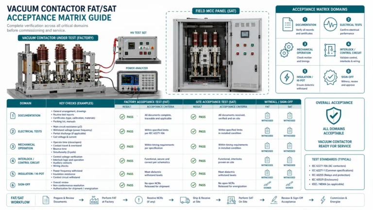
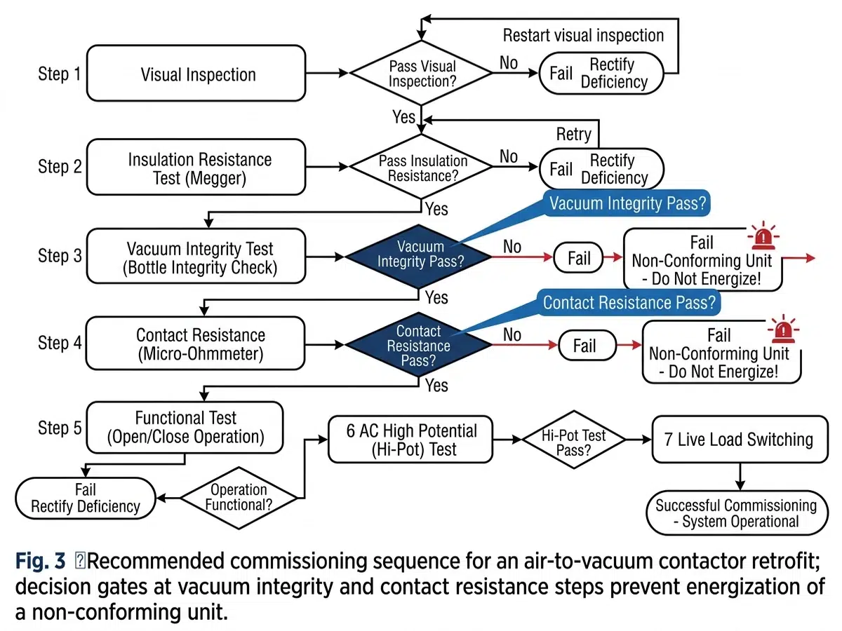
Prima di applicare l'alimentazione, completare le seguenti operazioni di verifica:
Alimentare solo l'alimentazione di controllo e verificare:
- Tensioni di pickup e dropout della bobina adeguate
- Temporizzazione della sequenza dei contatti ausiliari
- Funzionalità di interblocco con le apparecchiature associate
- Integrità del segnale di feedback PLC/DCS
- Funzionalità di controllo locale e remoto
Dopo aver eseguito con successo il test del circuito di controllo, procedere con il test di carico:
Documentare tutti i risultati dei test e confrontarli con le specifiche del produttore e i requisiti di base.
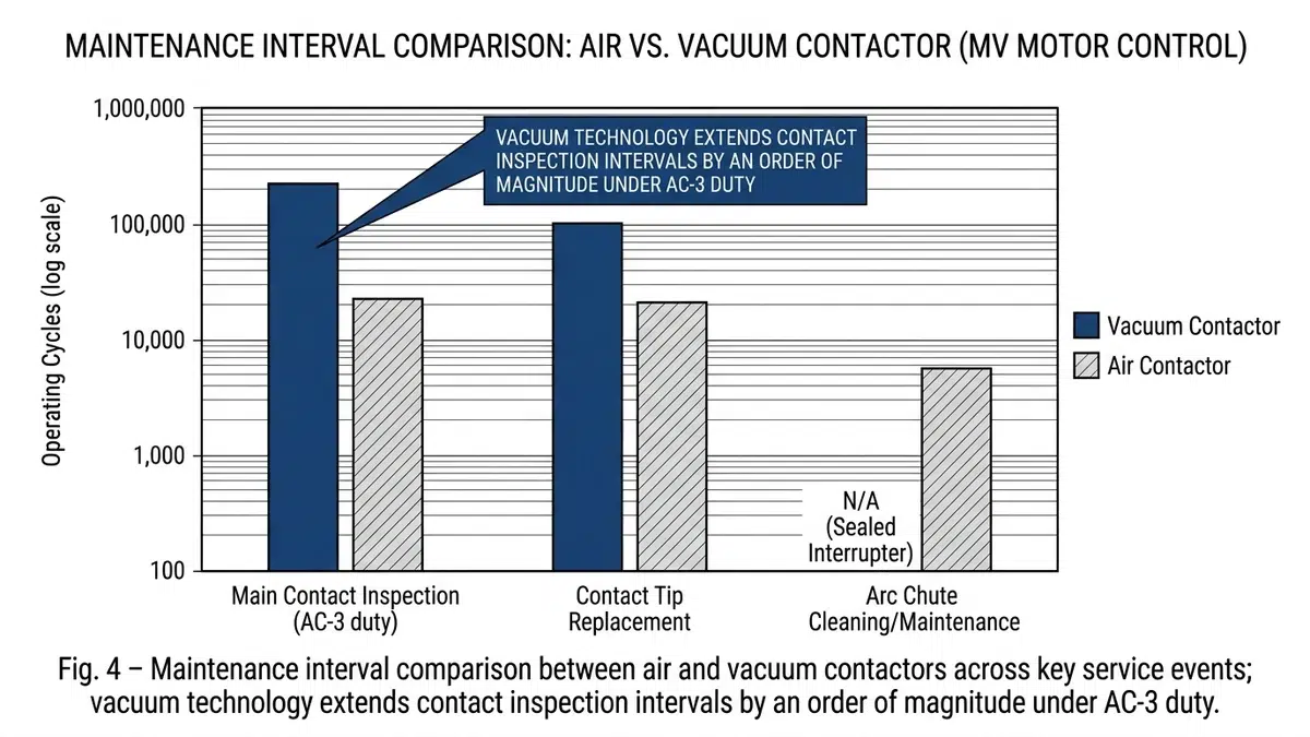
I contattori sotto vuoto riducono drasticamente i requisiti di manutenzione rispetto ai contattori ad aria:
| Attività di manutenzione | Contattore aria | Contattore a vuoto |
|---|---|---|
| Ispezione dei contatti | 6-12 mesi | 3-5 anni |
| Pulizia dello scivolo ad arco | 6-12 mesi | Non applicabile |
| Lubrificazione meccanica | Ogni anno | 2-5 anni |
| Revisione completa | 25.000-50.000 operazioni | Oltre 500.000 operazioni |
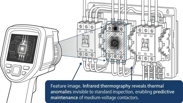
Nonostante la manutenzione ridotta, alcuni parametri richiedono un monitoraggio continuo:
– Sportello operativo: Operazioni di tracciamento rispetto alla vita nominale
– Indicatori di erosione da contatto: Molti contattori a vuoto moderni sono dotati di indicatori di usura
– Integrità del vuoto: Test periodico se l'unità non è dotata di monitoraggio integrale
– Condizione del contatto ausiliario: Si usurano più rapidamente dei contatti del vuoto principale
Mantenere un adeguato inventario di ricambi:
- Interruttori a vuoto di ricambio completi
- Moduli di azionamento elettronico della bobina
- Blocchi di contatti ausiliari
- Componenti di protezione dalle sovratensioni (snubber RC, MOV)
Sulla base dei progetti che ho gestito in vari settori, il ROI si verifica in genere entro 2-4 anni. Il calcolo include la riduzione della manodopera per la manutenzione (in genere 4-8 ore per contattore all'anno), l'eliminazione dei costi di sostituzione dello scivolo ad arco ($500-1.500 per unità), la riduzione dei tempi di inattività per la manutenzione e il miglioramento della protezione del motore che riduce i costi di riparazione del motore. Per gli impianti in funzione continua con più retrofit, il ritorno dell'investimento avviene spesso entro 18 mesi.
La sostituzione diretta è raramente possibile senza modifiche. Sebbene i contattori sottovuoto siano generalmente più piccoli, le differenze nelle configurazioni di montaggio, nei requisiti dei circuiti di controllo e nelle disposizioni delle sbarre richiedono in genere piastre di adattamento e modifiche al cablaggio. Tuttavia, i produttori offrono kit di retrofit specificamente progettati per semplificare l'installazione nei centri di controllo motore più comuni. Verificare sempre la compatibilità con il produttore del contattore e con il produttore del sistema MCC originale.
Le installazioni di retrofit spesso richiedono una protezione più estesa contro le sovratensioni perché i motori degli impianti esistenti possono avere sistemi di isolamento più vecchi con capacità di resistenza alle sovratensioni inferiori. I motori prodotti prima del 1995, in particolare quelli avvolti prima dell'adozione degli standard di isolamento per gli inverter, sono più suscettibili ai transitori di commutazione dei contattori a vuoto. Raccomando la protezione contro le sovratensioni per tutti i motori in cui le condizioni o l'età dell'isolamento sono incerte, indipendentemente dai valori teorici di BIL.
Il personale addetto alla manutenzione deve ricevere una formazione specifica del produttore che riguardi la manipolazione dell'interruttore del vuoto (fondamentale: non tentare mai di smontare le bottiglie del vuoto), la diagnostica e la sostituzione dell'azionamento elettronico della bobina, le procedure di test corrette per l'integrità del vuoto e le considerazioni sulla sicurezza specifiche dell'apparecchiatura installata. L'investimento in formazione previene errori costosi e garantisce la sicurezza del personale intorno alle apparecchiature a media tensione.
Esistono diversi metodi per verificare l'integrità del vuoto: test ad alto potenziale (la resistenza indica un vuoto adeguato), test con magnetron (un'apparecchiatura specializzata misura la pressione interna), osservazione a raggi X (mostra l'erosione dell'arco interno) e indicatori integrati nel produttore (alcuni progetti includono indicatori di durata). Per le applicazioni critiche, raccomando di stabilire una linea di base con il test del magnetron al momento della messa in servizio, seguito da verifiche periodiche a intervalli di 5 anni.
La documentazione completa deve includere la valutazione delle condizioni dell'apparecchiatura prima dell'intervento e fotografie, schemi di cablaggio dettagliati che confrontino le configurazioni esistenti e quelle nuove, disegni delle piastre di adattamento con dimensioni e specifiche di coppia, risultati dei test di messa in servizio (resistenza di isolamento, resistenza di contatto, temporizzazione, misure di sovratensione), disegni schematici e a linea singola aggiornati che riflettano le condizioni di costruzione e revisioni delle procedure di manutenzione per i requisiti dei contattori a vuoto. Questa documentazione supporta la manutenzione futura, soddisfa i requisiti normativi e facilita la risoluzione dei problemi.
Alcune applicazioni richiedono un'attenta valutazione prima di procedere: applicazioni di commutazione ad altissima frequenza (alcuni contattori pneumatici gestiscono meglio specifici scenari di inching/plugging), installazioni in cui la corrente di guasto del sistema supera i valori nominali dei contattori sotto vuoto disponibili, situazioni in cui l'integrazione del sistema di controllo presenta problemi di compatibilità insormontabili e strutture che stanno pianificando una sostituzione completa del centro di controllo motori a breve termine, in cui i costi di retrofit diventano sfavorevoli.
I retrofit da contattori ad aria a contattori a vuoto offrono vantaggi misurabili in termini di affidabilità, riduzione della manutenzione e sicurezza operativa se eseguiti correttamente. Il successo dipende da un'accurata valutazione pre-retrofit che affronti la compatibilità fisica, elettrica e del sistema di controllo.
I fattori critici di successo includono:
Valutazione completa della compatibilità prima dell'acquisto dell'apparecchiatura, comprese le dimensioni fisiche, i valori nominali elettrici e i requisiti del circuito di controllo
Progettazione corretta della protezione dalle sovratensioni in base all'età del motore, alle condizioni di isolamento e ai requisiti di commutazione.
Documentazione dettagliata sul cablaggio creato durante la rimozione e utilizzato per guidare la reinstallazione.
Committenza sistematica seguendo un protocollo strutturato che verifica la funzionalità meccanica, elettrica e del sistema di protezione
Procedure di manutenzione aggiornate che sfruttano i vantaggi dei contattori a vuoto mantenendo intervalli di monitoraggio appropriati
Formazione del personale garantire che il personale addetto alla manutenzione comprenda le diverse caratteristiche e i requisiti della tecnologia del vuoto
L'investimento in una pianificazione e in un'esecuzione corrette si traduce in dividendi per tutto il ciclo di vita dell'apparecchiatura. Le strutture che affrontano sistematicamente questi interventi di retrofit riportano riduzioni significative dei tempi di fermo non programmati, dei costi di manutenzione e degli incidenti di sicurezza.
Per un'ulteriore guida tecnica sui retrofit delle apparecchiature di media tensione, si consiglia di consultare lo standard IEEE C37.09 per il test degli interruttori ad alta tensione in CA, che fornisce protocolli pertinenti applicabili alla messa in servizio dei contattori sotto vuoto. Le risorse interne su [coordinamento della protezione dei motori], [manutenzione dei quadri di media tensione], [progettazione dei sistemi di protezione dalle sovratensioni] e [procedure di test degli interruttori sotto vuoto] forniscono informazioni supplementari a sostegno di progetti di retrofit di successo.