Vous avez besoin des spécifications complètes ?
Téléchargez notre catalogue de produits 2025 pour obtenir les schémas détaillés et les paramètres techniques de tous les composants des appareillages de commutation.
Obtenir le catalogue
Téléchargez notre catalogue de produits 2025 pour obtenir les schémas détaillés et les paramètres techniques de tous les composants des appareillages de commutation.
Obtenir le catalogue Téléchargez notre catalogue de produits 2025 pour obtenir les schémas détaillés et les paramètres techniques de tous les composants des appareillages de commutation.
Obtenir le catalogue
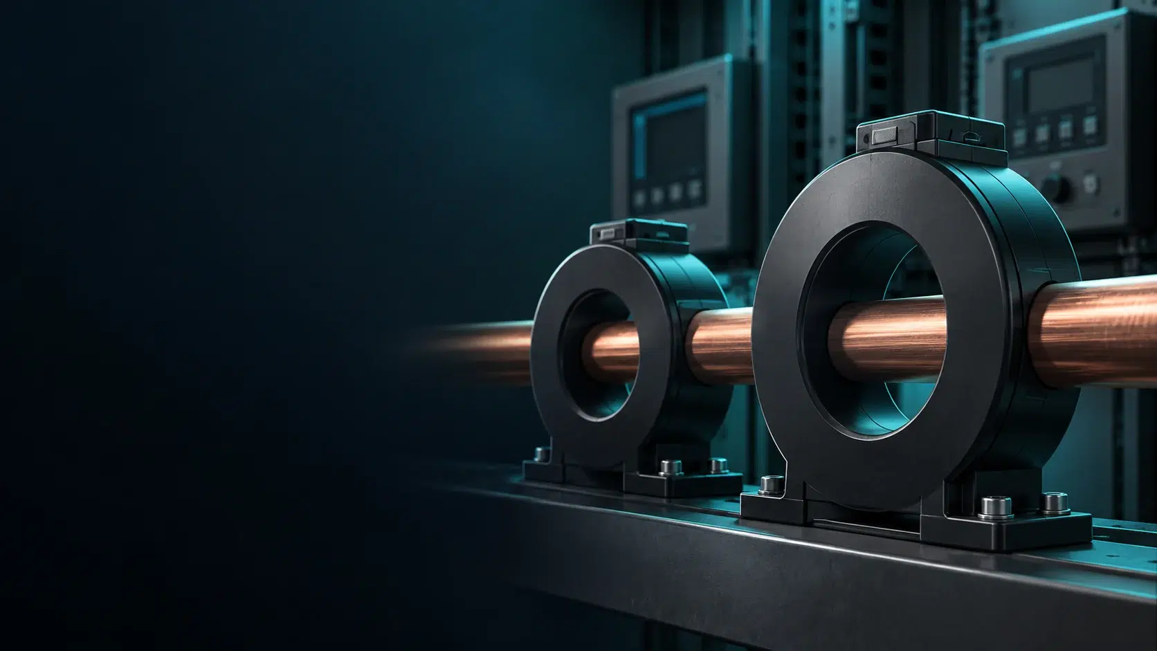
Understand CT accuracy classes 0.2S, 0.5S, 5P and 10P, including rated burden, effective ALF and checks for metering and protection applications.
Dernière mise à jour : .
Current transformers supply measuring instruments and protection relays with scaled current signals. Metering classes describe measurement accuracy over a specified load-current range; protection classes describe performance under the fault conditions covered by their designation. A metering-class label alone does not establish suitability for protection, and a protection-class label alone does not establish revenue-metering accuracy.
Ce guide décompose les désignations des classes de précision de la CEI 61869-2, explique les différences techniques entre les classes de mesure (0,1, 0,2, 0,5) et les classes de protection (5P, 10P), et fournit des conseils pratiques de sélection pour les applications de moyenne tension.
A CT accuracy class defines permissible errors under specified current, burden, frequency and test conditions. For a metering CT, the class number identifies the rated-current ratio-error limit; other test currents have their own limits. In a 5P or 10P designation, the number identifies the composite-error limit at the rated accuracy-limit primary current, not the ratio-error limit at normal load.
Il existe deux systèmes de classification distincts. Les classes de mesure (0.1, 0.2, 0.5, 1.0) optimisent la précision pour les courants de fonctionnement normaux - typiquement 5% à 120% du courant nominal. Les classes de protection (5P, 10P) donnent la priorité aux performances en cas de défaut, en maintenant la précision à des multiples de courant dépassant de loin le fonctionnement normal.
Metering and protection impose different design requirements. A CT may contain separate metering and protection cores, and some designs carry more than one accuracy designation. Select each core using its declared ratings and the connected equipment requirements; neither core size nor material alone proves its accuracy class.
Part of the primary ampere-turns supplies the core excitation rather than the secondary load. The resulting exciting current, together with the secondary circuit impedance, produces ratio error and phase displacement.
Erreur de rapport (ε) is the difference between the primary current inferred from the rated ratio and the actual primary current, expressed as a percentage of the actual primary current. With a rated ratio of 1000/5 A, a secondary reading of 4.98 A at 1000 A primary gives (200 × 4.98 − 1000) / 1000 × 100 = −0.4%. The error varies with current and burden.
Déplacement de phase (δ) mesure la différence angulaire entre les phases des courants primaire et secondaire, exprimée en minutes d'arc. La transformation idéale produit un déphasage nul ; les TC réels présentent de petits déplacements dus aux exigences du courant de magnétisation.
Core material, geometry, turns and excitation characteristics all influence CT performance. Rated output is stated in VA at the rated secondary current. Check the manufacturer’s declared burden range and burden power factor as well as the VA rating: a very small connected burden is not automatically within the metering accuracy guarantee.
The limits apply at the current and burden conditions specified for the class. At rated primary current, Class 0.2 has ratio-error and phase-displacement limits of ±0.2% and ±10 minutes. For protection classes, the rated-current ratio-error limits are ±1% for 5P and ±3% for 10P; their respective composite-error limits at the rated accuracy-limit current are 5% and 10%.
Metering classes specify ratio-error and phase-displacement limits at several test currents. The table lists the limits at 100% rated current and the covered current range. It does not mean that the rated-current error limit applies unchanged over that entire range; use the full class table and the CT’s declared burden conditions for selection.
| Classe | Erreur de rapport à 100% In | Phase displacement at 100% In | Specified current range | Application typique |
|---|---|---|---|---|
| 0.1 | ±0,1% | ±5 min | 5-120% | Étalons de référence de laboratoire |
| 0.2 | ±0,2% | ±10 min | 5-120% | Comptage des recettes de transport |
| 0.2S | ±0,2% | ±10 min | 1-120% | Comptage des revenus de la charge variable |
| 0.5 | ±0,5% | ±30 min | 5-120% | Comptage dans les sous-stations de distribution |
| 0.5S | ±0,5% | ±30 min | 1-120% | Comptage des recettes industrielles |
| 1.0 | ±1,0% | ±60 min | 5-120% | Instruments d'indicateurs |
The “S” suffix identifies metering classes with additional low-current requirements. Classes 0.2S and 0.5S include a 1% rated-current test point, whereas the ordinary classes listed above start at 5%. Error limits differ by test point. Select a class and ratio that cover the expected minimum load and the applicable metering requirements.
For variable-load facilities, compare the expected minimum primary current with the CT rating before choosing between 0.2 and 0.2S. Billing value alone does not define the required class. Include the meter, voltage measurement and wiring in the overall measurement-accuracy assessment.
Instrument security factor (FS) describes the overcurrent behavior specified for a metering core at rated burden. FS5 and FS10 are common declared ratings, but the accuracy class alone does not prescribe a universal saturation multiple. Reducing the connected burden can increase the current at which the core saturates. Verify FS and the meter’s withstand capability rather than assuming every metering CT saturates at 2–5 times rated current.
Metering CT selection checks
- Compare the expected minimum load with the class test points and the CT ratio.
- Verify the complete connected burden is within the CT’s declared metering accuracy range.
- Obtain the selected meter’s actual input burden; verify accuracy at the resulting total burden.
- Demander des certificats d'essai d'usine indiquant les erreurs réelles mesurées, et pas seulement la conformité à la classe.
Les classes de protection suivent un système de notation différent qui reflète leur fonction principale : la mesure précise du courant de défaut. La désignation “5P20” codifie trois paramètres essentiels pour la coordination des relais.
| Classe | Erreur composite à l'ALF | Valeurs communes de l'ALF | Application typique |
|---|---|---|---|
| 5P | ≤5% | 10, 15, 20, 30 | Overcurrent protection; verify each relay application |
| 10P | ≤10% | 10, 15, 20 | Overcurrent protection where the scheme accepts 10P |
Le accuracy limit factor (ALF) is the rated accuracy-limit primary current divided by the rated primary current. A 1000/5 A, 5P20 CT has a rated accuracy-limit current of 20,000 A at its rated burden. This is a defined steady-state error test condition, not a sharp physical saturation threshold or a guarantee of transient performance.
For a 5P20 CT, the composite error must not exceed 5% at 20 times rated primary current under the specified test conditions and rated burden. Composite error includes waveform distortion and is not a signed ±5% ratio-error band. DC offset, remanent flux and the required operating time can impose additional CT requirements.
Initial steady-state screening: if the scheme requires class accuracy at the maximum symmetrical through-fault current, compare the effective ALF at the actual burden with that fault-current multiple.
Required effective ALF ≥ Maximum symmetrical through-fault current ÷ CT rated primary current
For a 12.5 kA symmetrical fault and a 500/5 A CT, the fault-current multiple is 12,500 / 500 = 25.
At rated burden, 5P20 alone does not demonstrate the above 25-times screening requirement; a 5P30 rating would cover that steady-state multiple. Final selection still requires the relay manufacturer’s criteria, actual secondary burden, fault duration and transient assessment. Some protection functions tolerate partial CT saturation, so this screening rule is not a universal relay-sizing formula.
Protection CT selection also involves excitation characteristics, secondary winding resistance and short-time thermal and dynamic ratings. A 5P or 10P designation does not replace these checks. For differential or transient duties, the relay manufacturer may specify PX, PR or a transient class, or give a calculation for an acceptable P-class CT.
The following comparison summarizes the different performance specifications. Individual CTs can have additional ratings beyond the class names shown.
| Paramètre | CT de comptage | Protection CT |
|---|---|---|
| Fonction principale | Facturation des recettes, contrôle de l'énergie | Détection des défauts, fonctionnement des relais |
| Plage de précision | 1-120% de valeur nominale (classe S) | Rated error limit at ALF × rated current and rated burden |
| Spécification des erreurs | Erreur de rapport + déphasage | Rated-current ratio error and composite error at ALF |
| Comportement de saturation | Specified by FS and burden; not by metering class alone | Specified accuracy-limit and transient characteristics |
| Conception de base | Design depends on accuracy, burden and FS | Design depends on burden, fault and transient duty |
| Classes types | 0,2, 0,2S, 0,5, 0,5S, 1,0 | 5P10, 5P20, 10P10, 10P15 |
| Dispositifs connectés | Compteurs de kWh, analyseurs de puissance | Relais de protection, enregistreurs de défauts |
A saturated CT produces a distorted secondary waveform. Depending on the relay function and settings, this can delay operation or affect differential stability. The magnitude and timing of the effect must be assessed for the actual protection scheme; they cannot be inferred from the metering class alone.
Separate cores allow the metering burden and protection burden to be specified and tested independently when both functions are needed.
Connected burden affects the voltage the CT must develop and therefore its accuracy and saturation behavior. Include the relay or meter input and the complete secondary wiring circuit. Keep the metering burden within its declared accuracy range, and calculate protection performance at the actual burden.
Lead burden calculation for a separate outgoing and return pair:
Lead VA = Isecondary² × Rloop = Isecondary² × 2 × Rone-way
Example: a 50 m one-way run with a measured or calculated one-way resistance of 0.35 Ω has a 0.70 Ω loop. At 5 A, its burden is 25 × 0.70 = 17.5 VA; at 1 A, it is 0.70 VA. Use the cable resistance at the design temperature and the actual return-circuit arrangement.
Cela explique pourquoi les secondaires de 1 A conviennent aux longs parcours de câbles - la charge est réduite de 25 fois par rapport aux secondaires de 5 A pour un câble identique.
Liste de contrôle de la sélection :
Protection CT specification checks
- For auto-reclosing, assess remanence, fault duration and the required operating cycle.
- For differential protection, follow the selected relay’s CT ratio and saturation requirements.
- Use the relay’s actual input burden and the complete wiring burden when calculating effective ALF.
- Request excitation curves and secondary winding resistance when required by the protection calculation.
La plupart des installations moyenne tension nécessitent à la fois un comptage et une protection de chaque départ. Les TC bicanaux (ou multiconducteurs) répondent à ce besoin en incorporant des noyaux magnétiques distincts enroulés sur le même conducteur primaire.
Illustrative dual-core specification, subject to the actual meter, relay and wiring calculations:
Specify and verify the accuracy and burden of each core separately. Confirm metering FS, protection performance, insulation level and the assembly’s thermal and dynamic withstand ratings. Separate cores do not remove the need to coordinate the complete secondary circuits.
Intégration avec Disjoncteurs à vide moyenne tension requires a common system fault study. ALF is a dimensionless ratio and cannot be compared directly with a breaker breaking-current rating in kA. Evaluate the CT against the maximum through-fault current, its primary rating, actual burden and relay requirements. Separately verify the CT short-time/dynamic withstand ratings and the breaker interrupting duty. Ask the fabricants de composants for the data needed to complete those checks.
Lorsque vous spécifiez des TC pour de nouvelles installations, fournissez les informations suivantes à votre fournisseur :
Review the following specification errors before purchasing or replacing a CT.
A metering class alone does not verify fault-current performance. Solution : select a core with the protection characteristics required by the relay scheme and verify its performance at the actual burden, through-fault current and required operating time.
Long secondary circuits can add substantial burden, particularly at 5 A. Solution : calculate the complete loop resistance at the design temperature. Compare 1 A and 5 A options using the actual cable and compatible relay inputs; cable length alone is not a universal selection threshold.
Different saturation behavior can produce unwanted differential current during an external fault. Solution : use the relay manufacturer’s ratio-compensation, excitation, winding-resistance and stability requirements. Transformer differential schemes may use different primary CT ratios; identical ratios and knee-point voltages are not a universal requirement.
Remanent flux can change CT saturation during a subsequent fault or reclosing sequence. Solution : assess the specified operating cycle, system time constant and relay requirements. Select suitable remanence or transient performance where required; a blanket 50% ALF increase is not a verified substitute.
Compréhension Caractéristiques nominales des disjoncteurs à vide helps establish the switching duty. CT accuracy selection is a separate calculation based on the actual through-fault duty and protection scheme, while CT thermal/dynamic withstand must also cover the clearing duty.
5P20 specifies a protection CT with a composite-error limit of 5% at a rated accuracy-limit current of 20 times rated primary current, at rated burden and the specified test conditions. For a 400/5 A CT this test current is 8,000 A. It does not identify an exact saturation threshold or guarantee performance for every transient waveform.
Do not assume that a Class 0.5 metering core is suitable for protection. Its class establishes metering accuracy under specified conditions, not the fault-current performance required by a relay. Use a core whose declared protection characteristics have been checked against the particular relay scheme.
Consider 0.2S when accurate measurement is required at low load, especially between 1% and 5% of rated CT current. The required class also depends on the utility or project metering specification. Check the limits at each current test point and the declared burden range; 0.2S does not mean ±0.2% at every current.
A lower external burden generally increases the effective ALF of a P-class CT, but winding resistance must be included. For mainly resistive burdens, ALFactual ≈ ALFévaluée × (Rct + Rrated burden) / (Rct + Ractual burden). Therefore, halving external burden does not generally double ALF. Use manufacturer data for the actual circuit and transient duty.
Knee-point voltage characterizes the bend in the secondary excitation curve. The IEC convention uses the point at which a 10% voltage increase produces a 50% increase in exciting current. It is particularly relevant when specifying PX-type CTs. Apply the relay manufacturer’s knee-point, excitation-current and winding-resistance requirements; a simple voltage comparison does not establish suitability for every protection scheme.
IEC 61869-2 includes metering classes such as 0.2 and 0.5 and protection classes such as 5P, 10P and PX. IEEE C57.13 uses a different set of designations, including voltage-based relaying classes such as C100 and C200. The test conditions and burden definitions differ. Specify the standard required by the project and compare the full ratings rather than treating the class names as direct equivalents.
A capacitor bank can need phase overcurrent, earth-fault and sensitive unbalance protection, each with different measurement duties. Select CT ratio, accuracy, burden and transient performance from the bank configuration, expected unbalance level and relay instructions. A universal 5P10 or 0.5 recommendation cannot establish suitability for all capacitor banks.
Pour un support de spécification CT adapté à vos besoins en matière d'appareillage, contactez l'équipe d'ingénieurs de XBRELE via la page de contact technique. Nous proposons des solutions intégrées combinant technologie de l'interrupteur à vide avec des transformateurs d'instrumentation correctement coordonnés pour des performances fiables en matière de comptage et de protection, y compris contrôle de la coordination des relais pour les alimentations de transformateurs.
Technical references: IEC 61869-2:2012 — inductive current transformers; ABB — calculation of actual accuracy limit factor; ABB — CT requirements for non-directional overcurrent protection; ABB — transformer differential CT requirements. The ABB application notes explain calculation methods; final selection must use the applicable project standard and the selected relay’s current instructions.