Vous avez besoin des spécifications complètes ?
Téléchargez notre catalogue de produits 2025 pour obtenir les schémas détaillés et les paramètres techniques de tous les composants des appareillages de commutation.
Obtenir le catalogueTéléchargez notre catalogue de produits 2025 pour obtenir les schémas détaillés et les paramètres techniques de tous les composants des appareillages de commutation.
Obtenir le catalogueTéléchargez notre catalogue de produits 2025 pour obtenir les schémas détaillés et les paramètres techniques de tous les composants des appareillages de commutation.
Obtenir le catalogue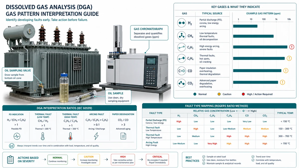
L'analyse des gaz dissous (AGD) est le principal outil de diagnostic permettant de détecter les défauts naissants à l'intérieur des transformateurs à huile avant qu'ils n'évoluent vers une défaillance catastrophique. Ce guide explique comment interpréter les profils de gaz, appliquer les méthodes de rapport, définir des niveaux d'intervention, prélever des échantillons valides et intégrer l'AGD dans un programme de maintenance structuré. Il aborde également les décisions d'achat qui déterminent si un transformateur peut être surveillé de manière rentable tout au long de sa durée de vie.
Avant d'appliquer les méthodes basées sur les rapports ou les seuils d'intervention, associez le profil gazeux dominant à un type de faille probable à l'aide du tableau ci-dessous. Il s'agit du premier filtre appliqué dès la réception d'un nouveau résultat de laboratoire.
| Symptôme (composition dominante des gaz) | Premier test | Cause première probable | Action suivante |
|---|---|---|---|
| Uniquement H₂ ou H₂ + CH₄ (en faible quantité) ; faible teneur en C₂H₂ | Vérifier la teneur en eau de l'huile ; contrôler l'état du reniflard | Décharges partielles (DP) dans l'huile contaminée par l'humidité | Planifier des tests de performance hors ligne ; réduire la fréquence d'échantillonnage à une fois par mois |
| Taux élevés de CH₄ et C₂H₆ ; taux négligeables de C₂H₂ | Consulter l'historique des charges et les journaux du système de refroidissement | Défaut thermique en dessous de 300 °C ; flux parasite ou huile surchauffée | Inspecter les ventilateurs de refroidissement et les radiateurs ; vérifier la charge par rapport aux indications de la plaque signalétique |
| C2H4 prédominant + CH4 ; faible teneur en C2H2 | Calculer le rapport C2H4/C2H6 ; vérifier le nombre d'opérations LTC | Défaut thermique entre 300 et 700 °C ; courants de circulation ou mauvais contacts | Réduire la charge ; prévoir un arrêt pour inspection dans les 60 jours |
| Taux élevés de C2H4 et C2H2 ; taux élevé d'H2 | Appliquer le triangle de Duval ; vérifier le taux de variation | Défaut thermique supérieur à 700 °C ; point chaud intense avec formation d'arcs électriques | Accélérer la coupure ; procéder à un nouveau prélèvement dans les 72 heures |
| C2H2 prédominant + H2 ; présence de C2H4 | Vérifier la conformité aux rapports prévus par la norme CEI 60599 ; contrôler séparément l'huile du changeur de prises | Arc électrique à haute énergie ; claquage interne ou défaut du changeur de prises | Envisager une mise hors tension immédiate |
| Augmentation des concentrations de CO et de CO₂ en présence d'hydrocarbures | Mesurer le rapport CO/CO₂ ; demander une analyse du furane | Dégradation de la cellulose associée à un défaut thermique | Évaluer la teneur en humidité ; programmer un prélèvement de furanes |
| Uniquement CO et CO₂ ; H₂ en quantités minimes | Consulter l'historique des charges à long terme | Vieillissement normal ou surchauffe de l'isolation en papier | Analyse de la tendance ; aucune intervention électrique n'est nécessaire dans l'immédiat |
Principe fondamental : Une concentration d'acétylène supérieure à 1-2 ppm dans un transformateur hermétique n'ayant pas fait l'objet de défauts de traversée récents constitue l'indicateur le plus fiable justifiant une intervention immédiate, quels que soient les autres niveaux de gaz. Le taux de variation est souvent le premier signe avant-coureur ; une concentration de méthane ayant doublé en quatre semaines est plus préoccupante qu'une concentration identique restée stable pendant six mois.
Avant d'interpréter tout résultat d'analyse DGA, vérifiez que le matériel d'échantillonnage, les méthodes de laboratoire et les étalons de référence répondent aux critères ci-dessous. Un échantillon vicié ne peut pas être corrigé par la suite au niveau de l'analyse.
| Instrument ou source | Rôle fonctionnel | Critère d'acceptation |
|---|---|---|
| Seringue en verre (60-100 ml, étanche aux gaz, raccord Luer-Lock) | Prélèvement d'échantillons d'huile de référence | Test d'étanchéité effectué avant la sortie ; utilisé pendant la durée de vie certifiée ; verre borosilicaté uniquement |
| Cylindre sous pression en acier inoxydable (250 ml) | Prélèvement sur des conduites de longue distance ou à haute pression | Fermeture par robinet à boisseau sphérique ; conçu pour la pression sur site ; conservation de l'échantillon pendant <= 30 jours |
| Chromatographe en phase gazeuse avec détecteur TCD/FID (GC-TCD/FID) | Déterminer les neuf gaz clés conformément à la norme CEI 60567 | Laboratoire accrédité ISO/IEC 17025 ; étalonnage réalisé à l'aide d'un mélange gazeux étalon certifié |
| Chromatographe en phase gazeuse portable (triage sur place) | Triage en fonction du taux de variation instantané | Étalonnage effectué dans les 30 jours ; l'opérateur possède des compétences attestées ; confirmation par analyse d'échantillons en double avec un laboratoire de référence |
| Moniteur DGA multigaz en ligne | Détection continue des tendances entre des échantillons prélevés manuellement | Réétalonnage en usine dans un délai de 12 à 18 mois ; seuils d'alarme définis dans la documentation du programme |
| Analyseur photoacoustique (laboratoire) | Rapports de surveillance des gaz de routine | N'est pas utilisé pour les calculs de rapport lorsque les concentrations individuelles de gaz sont inférieures à 10 ppm |
| Relais de Buchholz avec chambre de collecte de gaz | Enregistrement des événements de protection ; détection des défauts graves | Étalé et testé avant expédition ; volume et couleur du gaz enregistrés à chaque trajet |
| IEC 60599 | Référence relative à la méthode du rapport et limites des zones de faille | Édition actuelle ; à utiliser pour les déclarations réglementaires et l'interprétation des ratios dans les cas limites |
| IEEE C57.104 | Seuils d'intervention 1 à 4 ; limites TDCG | Édition actuelle ; demander des décisions individuelles concernant les seuils applicables au gaz et au TDCG |
| Manuel du transformateur OEM | Données de référence et de refroidissement spécifiques à l'équipement | Les résultats de l'analyse par décomposition gazeuse (DGA) effectuée lors de la réception en usine sont requis comme premier point de référence dans l'historique des tendances |
| Spécification du projet | Niveaux d'alerte spécifiques au site et obligations en matière d'intervention | Les niveaux d'intervention contractuels doivent être au moins égaux ou supérieurs aux valeurs minimales de la norme IEEE C57.104 |

Les concentrations de gaz bruts vous indiquent ce qui est présent. Les rapports de gaz vous indiquent pourquoi ces gaz sont présents. Utilisez les méthodes ci-dessous comme des vérifications croisées plutôt que comme des règles isolées de type « réussite/échec ».
| Critère | Ratios de Rogers | IEC 60599 | Triangle de Duval |
|---|---|---|---|
| Peut renvoyer un résultat indéfini | Oui | Oui | Non |
| Gère les erreurs mixtes | Pauvre | Modéré | Mieux |
| Nécessite une valeur C2H2 > 0 pour une précision optimale | Oui (R2 échoue) | Oui (le critère 1 n'est pas rempli) | Non |
| Utilisation de l'hydrogène (H₂) pour la cartographie des failles | Oui (R1) | Oui | Non |
| Références normatives | IEC 60599 / IEEE C57.104 | IEC 60599 | IEC 60599 |
| Meilleur cas d'utilisation | Mécanisme unique, défaut évident | Déclarations réglementaires | Tendances, failles mixtes |
| Risque lié à de faibles concentrations de gaz | Élevé | Élevé | Modéré |

L'interprétation des profils de gaz DGA n'a de valeur que si elle débouche sur une décision claire. Le système d'actions par paliers présenté ci-dessous s'appuie sur les recommandations de la norme CEI 60599 et les limites de la norme IEEE C57.104 pour les transformateurs de puissance d'une tension nominale de 69 kV et plus.
| Niveau | Étiquette | Conditions de déclenchement | Action requise | Calendrier |
|---|---|---|---|---|
| 1 | Normal – Poursuivre la surveillance | Tous les gaz sont en dessous des limites du niveau 1 ; ROC stable ; aucun indicateur de taux de défaillance | Conserver l'intervalle d'échantillonnage standard | Ce n'est pas urgent |
| 2 | Attention – Augmenter la fréquence d'échantillonnage | Tout gaz entre le niveau 1 et le niveau 2 ; ROC > 101 TP3T par mois pour n'importe quel gaz clé ; indicateur de ratio unique sans hausse corroborante du gaz | Réduire la fréquence des prélèvements à une fois par mois ; examiner l'historique des charges ; vérifier le système de refroidissement | Dans les 30 jours |
| 3 | Avertissement – Réduction de la charge et enquête | Tout gaz dépasse le niveau 2 ; C2H2 > 3 ppm avec une tendance à la hausse ; plusieurs gaz augmentent simultanément ; deux indicateurs de rapport ou plus correspondant au même type de défaut | Réduire la charge au niveau indiqué sur la plaque signalétique ; programmer une inspection hors ligne dans les 60 jours ; passer à un échantillonnage hebdomadaire | Dans un délai de 7 jours |
| 4 | Critique – Mise hors tension immédiate | C2H2 > 35 ppm avec courbe ROC rapide ; H2 > 1 800 ppm ; CO > 1 500 ppm en association avec l'acétylène ; tout gaz dont la concentration double en moins de 30 jours ; courbe de Duval dans la zone D2 | Mettre hors service ; ne pas remettre sous tension avant une inspection interne et la validation par le service technique | Immédiate |
| Gaz | Niveau 1 (Entrée sous réserve) | Niveau 2 (Avertissement) |
|---|---|---|
| Hydrogène (H₂) | 100 | 700 |
| Méthane (CH₄) | 120 | 400 |
| Éthylène (C₂H₄) | 50 | 200 |
| Éthane (C₂H₆) | 65 | 150 |
| Acétylène (C₂H₂) | 3 | 35 |
| Monoxyde de carbone (CO) | 350 | 900 |
| Dioxyde de carbone (CO2) | 2,500 | 10,000 |
| Gaz combustible total (GCT) | 720 | 1,920 |
Étape 1 – Sélectionner les concentrations absolues. Si la concentration d'un gaz dépasse le niveau 2, attribuez le niveau 3 avant de poursuivre. Si la concentration d'acétylène dépasse 35 ppm ou si la concentration d'un gaz a doublé depuis le dernier prélèvement, attribuez le niveau 4 et interrompez l'analyse en attendant l'arrêt de l'installation.
Étape 2 – Calculer le taux de variation. Un ROC supérieur à 1 ppm/jour pour l'acétylène ou à 10 ppm/jour pour l'hydrogène justifie un classement au niveau 3 au minimum, quelle que soit la concentration absolue.
Il convient de ne pas tenir compte du tableau des niveaux habituel lorsque de l'acétylène apparaît soudainement, qu'un gaz clé double de concentration entre deux échantillons, que des événements de relais coïncident avec une augmentation de la concentration de gaz, ou qu'un transformateur à bobines ouvertes (OLTC) partage son huile avec le réservoir principal. Dans ces cas-là, la vitesse de variation et le contexte de fonctionnement ont plus de poids qu'une simple valeur absolue en ppm.
Cet exemple concret anonymisé montre comment un modèle DGA peut passer de la surveillance des tendances à la planification des arrêts de production lorsque les concentrations d'éthylène et d'acétylène augmentent simultanément.
Contexte : Un autotransformateur de 63 MVA mis en service en 2007 enregistre en moyenne 28 opérations de commutation de prise par jour. Un échantillon de gaz dissous dans l'huile (DGA) a été prélevé six semaines après un prélèvement imprévu déclenché par un transitoire du relais de protection. La température de l'huile est supérieure de 5 à 8 °C à la valeur de référence de l'unité en raison d'une augmentation du débit.
Concentrations de gaz mesurées (ppm) :
| Gaz | Exemple actuel | Échantillon précédent (il y a 6 semaines) |
|---|---|---|
| H2 | 95 | 78 |
| CH₄ | 310 | 205 |
| C2H2 | 14 | 9 |
| C2H4 | 480 | 310 |
| C2H6 | 190 | 140 |
| LE CO | 420 | 390 |
| CO₂ | 3,900 | 3,600 |
Diagnostic : Le C2H4 est prédominant et augmente d'environ 28 ppm par semaine. Le rapport C2H4/C2H6 de 2,53 correspond à des températures localisées du pétrole supérieures à 500 °C. Le rapport C2H2/C2H4 de 0,029 indique que des arcs électriques de faible énergie au niveau des contacts du changeur de prises pourraient être un facteur plausible, compte tenu du nombre élevé de cycles de fonctionnement. Les coordonnées du triangle de Duval situent l'échantillon dans la zone T2-T3, avec une tendance vers T3. La tendance du CO est relativement plate, ce qui indique que la cellulose n'est pas le principal matériau à l'origine de la défaillance à ce stade. Ce résultat est Niveau 3: réduction de la charge et enquête requise dans un délai de sept jours.

L'interprétation précise des profils gazeux issus de l'analyse DGA dépend entièrement de la qualité de l'échantillon d'huile remis au laboratoire. Un échantillon de mauvaise qualité entraîne des erreurs de mesure qu'aucune méthode d'analyse ne peut corriger en aval.
Prélevez l'huile au niveau de la vanne de prélèvement inférieure prévue à cet effet après avoir purgé l'huile stagnante du raccord et du tuyau. Évitez de prélever des échantillons provenant uniquement du réservoir de compensation pour le diagnostic des défauts, car ceux-ci peuvent sous-estimer la présence de gaz plus lourds et fausser le profil gazeux.
| Point de contrôle | Action requise | Conséquence d'une omission |
|---|---|---|
| Élimination de l'air lors du remplissage de la seringue | Remplir la seringue en la plongeant dans le flux d'huile ; veiller à ce qu'il n'y ait pas de bulles d'air | Dilution par l'oxygène et l'azote ; rapports de gaz de faille artificiellement réduits |
| Prévention de la surpression dans les seringues | Après le remplissage, abaisser légèrement le piston pour obtenir un espace libre de 5 à 10 ml | Le gaz dissous s'échappe si la pression dans le corps de la seringue descend en dessous du seuil de saturation |
| Étiquetage et chaîne de traçabilité | Enregistrer l'identifiant du transformateur, la puissance nominale en MVA, la classe de tension, la charge au moment de l'échantillonnage, la température de l'huile, la date et l'heure | Résultats mal attribués ; fausses tendances |
| Température de transport | Conservez les échantillons à une température comprise entre 5 °C et 25 °C | La congélation provoque la rupture des seringues en verre ; une température supérieure à 35 °C accélère la perte de gaz |
| Durée maximale de conservation avant analyse | Seringue en verre : <= 72 heures ; cylindre en acier inoxydable : <= 30 jours | La perte progressive d'hydrogène du verre après 72 heures, telle que décrite dans le document CIGRE TB 771 |
1. Vérification du rapport oxygène/azote. Dans les transformateurs à cuve étanche, le rapport O₂/N₂ doit être compris entre environ 0,3 et 0,5. Un rapport supérieur à 0,5 indique une contamination par l'air ; rejetez l'échantillon et prélevez-en un nouveau.
2. Corrélation avec l'humidité. Vérifiez que la teneur en eau dissoute (en ppm selon la méthode Karl Fischer) est plausible compte tenu de la classe d'isolation et de l'historique des températures. Une valeur supérieure à la saturation en huile à la température mesurée suggère une erreur d'échantillonnage importante ou une fuite au niveau du joint.
Un résultat DGA dépourvu d'un processus de réponse défini n'a qu'une valeur limitée en termes de maintenance. Son interprétation ne devient exploitable que lorsqu'elle s'inscrit dans un programme précisant qui examine les résultats, à quelle fréquence, par rapport à quels seuils et avec quelle autorité de remontée.
| Couche | Fonction | Propriétaire type |
|---|---|---|
| Échantillonnage | Prélever des échantillons d'huile à intervalles réguliers | Technicien de terrain |
| Analyse | Effectuer des analyses chromatographiques, déterminer les concentrations de gaz | Moniteur de laboratoire ou sur site |
| Interprétation | Appliquer des méthodes de calcul de ratios, comparer aux seuils, classer les types de défauts | Ingénieur ou spécialiste en diagnostic |
| Action | Autoriser une réduction de charge, une inspection ou une coupure | Gestionnaire d'actifs ou responsable des opérations |
Définissez le prochain intervalle d'échantillonnage en fonction à la fois du niveau TDCG et du taux de variation. Les résultats stables de niveau 1 peuvent être suivis à des intervalles de routine, tandis que les résultats en hausse de niveau 2 ou 3 nécessitent des intervalles plus courts et la désignation de responsables de l'escalade.
| Niveau TDCG | Plage de concentration (ppm) | Réponse du programme |
|---|---|---|
| Niveau 1 | Moins de 720 | Maintenir l'intervalle d'échantillonnage habituel ; aucune mesure n'est requise |
| Niveau 2 | 720-1,920 | Augmenter la fréquence d'échantillonnage ; examiner les tendances de chaque gaz ; appliquer le triangle de Duval |
| Niveau 3 | 1,921-4,630 | Effectuer des prélèvements toutes les 1 à 4 semaines ; élaborer un plan d'urgence ; envisager une réduction de la charge si la tendance est à la hausse |
| Niveau 4 | Plus de 4 630 | Envisagez une mise hors tension immédiate ; consultez le service technique avant la prochaine mise sous tension |
Une interprétation hors contexte. Une analyse de la concentration de gaz effectuée sans tenir compte de l'historique des échantillons, du profil de charge ou de l'âge du transformateur aboutit à des conclusions peu fiables ; les analystes doivent avoir accès à l'historique complet des analyses de gaz de transformateur.
Lacunes en matière de pouvoir d'action. Si l'ingénieur chargé d'interpréter les résultats n'est pas habilité à autoriser une réduction de charge ou une coupure, et que la personne compétente ne reçoit pas cette interprétation, le processus est bloqué. Définissez clairement la procédure d'escalade, en précisant qui reçoit le rapport et dans quels délais.

Une interprétation efficace des profils de gaz DGA commence avant même la mise sous tension du transformateur. Les décisions d'achat prises dès la phase de définition des spécifications déterminent si un appareil pourra faire l'objet d'une surveillance rentable tout au long de sa durée de vie.
Emplacement de la vanne de prélèvement d'huile. Il faut prévoir au minimum une vanne de prélèvement en bas et une vanne d'huile en haut, toutes deux conçues pour permettre le prélèvement à l'aide d'une seringue ou d'un flacon sous vide sans mise hors tension. Éviter les vannes de prélèvement situées au-dessus du niveau d'huile pour les équipements critiques en raison du risque d'entrée d'air.
Relais de Buchholz et collecte des gaz. Pour les installations d'une puissance supérieure à 1 MVA, il convient de prévoir un relais de Buchholz équipé d'une chambre de collecte de gaz permettant un prélèvement à l'aide d'une seringue, placé sur la conduite reliant le réservoir au conservateur.
| Critère | Preuve minimale acceptable |
|---|---|
| Accréditation des laboratoires | Accréditation ISO/IEC 17025 avec la DGA incluse dans le champ d'application |
| Qualification du personnel chargé de l'échantillonnage | Techniciens certifiés selon la procédure d'échantillonnage de la norme CEI 60567 ou ayant suivi une formation équivalente attestée par un document officiel |
| Délai d'exécution | Engagement écrit : résultats des analyses de routine dans un délai de 5 jours ouvrables ; résultats des analyses signalées comme urgentes dans un délai de 24 heures |
| Service d'interprétation | Procédure formalisée pour aller au-delà des simples chiffres : ratios appliqués, analyse du contexte des tendances |
| Format de rapport | Rapport structuré comprenant une comparaison des tendances, une analyse des ratios et des recommandations classées par niveau d'action |
| Traçabilité des équipements | Les rapports d'étalonnage du chromatographe en phase gazeuse sont disponibles sur demande |
Pour les transformateurs existants, l'intérêt d'une mise à niveau dépend de la disponibilité d'un point de prélèvement d'huile fiable, de la mise en place de procédures d'isolation sûres, ainsi que de l'importance stratégique de l'installation, qui doit être suffisante pour justifier une surveillance en temps réel. Il convient au minimum de mettre en place une procédure de prélèvement documentée et de disposer d'une analyse de gaz de décomposition de référence avant de se fier à l'interprétation des tendances.
Utilisez ces références XBRELE pour relier la décision sur le terrain au produit correct, au test et au flux de travail de l'approvisionnement : Page produit XBRELE, Gamme de disjoncteurs à vide XBRELE, Guide de notation de la VCB, Liste de contrôle pour l'acceptation du TFA/TSA par le VCB, Gamme de transformateurs de distribution d'énergie XBRELE.
Pour le contexte de la méthode externe, comparez la procédure du site avec la procédure publique. Page des normes IEEE C37.09 et appliquer le manuel de l'équipementier et les spécifications du projet pour l'équipement fourni.
| Instrument / Source | Rôle d'acceptation | Risque en cas de perte |
|---|---|---|
| Manuel du fabricant | Définit les limites spécifiques au modèle, le courant d'essai et la tolérance de contrôle | Des limites trop générales peuvent entraîner des résultats faussement positifs ou des fausses alertes |
| Spécification du projet | Définit la source d'acceptation du site, le format des rapports, le niveau de test d'isolation et la fréquence de maintenance | Les résultats peuvent être conformes sur le plan technique, mais non conformes sur le plan contractuel |
| Testeur de résistance de contact / micro-ohmmètre | Mesure l'état des contacts en micro-ohms sous un courant contrôlé | Les mesures du multimètre ne permettent pas de déterminer les seuils d'alarme |
| Rapport d'essai d'acceptation en usine | Fournit la référence du numéro de série et les conditions de test | Aucun point de comparaison valable pour l'évolution du site |
Exemple concret : lors d'une inspection de maintenance, une phase a été mesurée en dehors des valeurs de référence de mise en service, tandis que les deux autres phases sont restées stables. L'équipe a répété la mesure avec des câbles vérifiés, a contrôlé la synchronisation et la course des contacts, et s'est appuyée sur l'écart mesuré pour distinguer un problème de pression de contact d'un simple problème de nettoyage de surface. La mesure corrective a été consignée dans le tableau de dépannage afin que le prochain échantillon de DGA, la note d'inspection et le registre de maintenance puissent être comparés à la même carte des défauts.
L'acétylène (C₂H₂) revêt la plus grande importance diagnostique, car il n'est produit en quantités significatives que par des décharges électriques de haute énergie. Toute détection confirmée supérieure à 1-2 ppm dans un transformateur scellé n'ayant pas fait l'objet de défauts de traversée récents justifie une enquête.
La fréquence d'échantillonnage devrait être déterminée en fonction du niveau de risque plutôt que d'être uniforme. Un transformateur neuf n'ayant jamais fait l'objet d'un rapport de panne nécessite généralement un échantillonnage annuel.
Non. La méthode DGA s'applique spécifiquement aux transformateurs à huile, car les gaz de diagnostic sont produits par la décomposition thermique et électrique de l'huile isolante et de la cellulose imprégnée d'huile.
Un rapport CO/CO₂ inférieur à 0,1 correspond à un vieillissement naturel du papier. Les rapports supérieurs à 0,3 indiquent une dégradation active de la cellulose impliquant des mécanismes thermiques.
Les méthodes basées sur les rapports ne sont pas fiables lorsque les concentrations absolues de gaz sont faibles, car les faibles incertitudes de mesure en laboratoire entraînent d'importantes variations dans les valeurs calculées. Elles ne sont pas non plus fiables lorsque plusieurs types de failles sont actifs simultanément.
Les trois erreurs les plus courantes qui invalident les résultats sont les suivantes : la contamination par l'air lors du remplissage de la seringue, qui réduit les concentrations de gaz indicateurs et fait passer le rapport O₂/N₂ au-dessus de 0,5 ; le dépassement du temps de maintien de 72 heures pour les seringues en verre, ce qui entraîne une perte mesurable d'hydrogène ; et le prélèvement de l'échantillon par le haut du réservoir ou du conservateur plutôt que par la vanne de vidange inférieure, ce qui sous-estime les gaz de défaut plus lourds. Tout résultat indiquant un rapport O2/N2 supérieur à 0,5 dans un transformateur à réservoir scellé doit être rejeté et un nouvel échantillon prélevé avant toute décision de maintenance.
Un transformateur en ligne (OLTC) dont l'huile est en communication avec le réservoir principal génère un bruit de fond persistant de C2H2 dû aux arcs électriques normaux qui se produisent lors des changements de prises. Ce bruit de fond doit être établi comme référence spécifique à l'appareil plutôt que d'être comparé directement aux tableaux standard de l'IEEE ou de la CEI.