Vous avez besoin des spécifications complètes ?
Téléchargez notre catalogue de produits 2025 pour obtenir les schémas détaillés et les paramètres techniques de tous les composants des appareillages de commutation.
Obtenir le catalogueTéléchargez notre catalogue de produits 2025 pour obtenir les schémas détaillés et les paramètres techniques de tous les composants des appareillages de commutation.
Obtenir le catalogueTéléchargez notre catalogue de produits 2025 pour obtenir les schémas détaillés et les paramètres techniques de tous les composants des appareillages de commutation.
Obtenir le catalogue
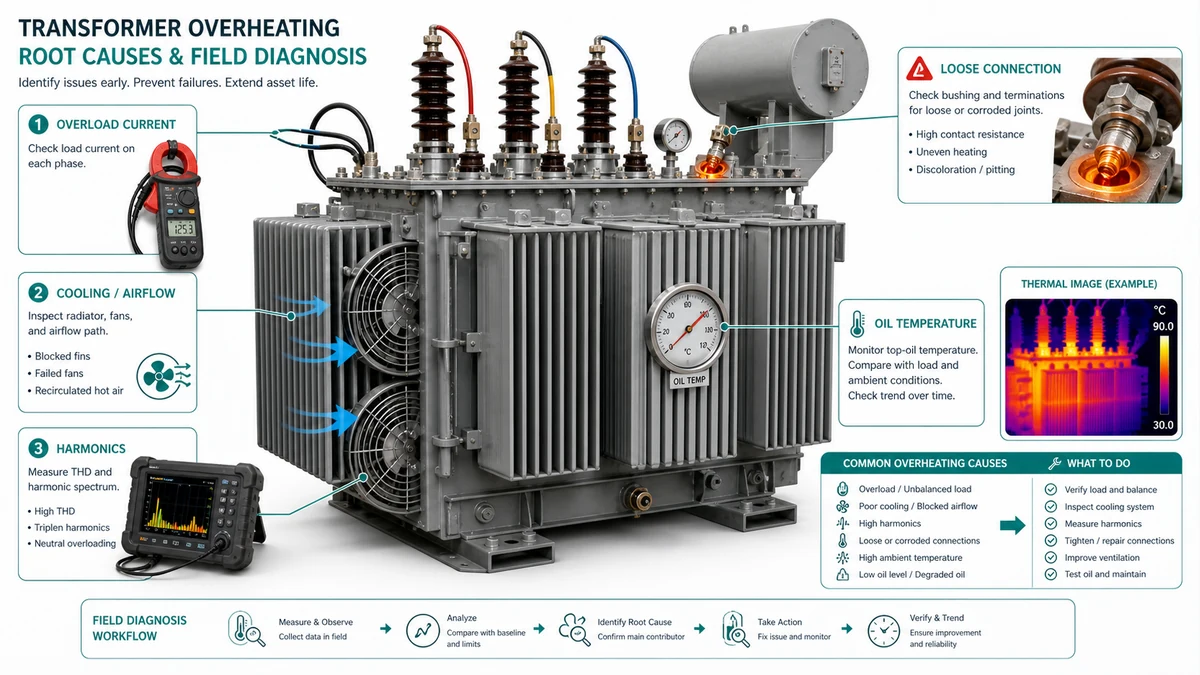
La surchauffe des transformateurs réduit la durée de vie de l'isolation plus rapidement que n'importe quelle autre contrainte de fonctionnement. La norme IEEE C57.91 établit que chaque augmentation de 6 °C au-dessus de la température nominale réduit de moitié la durée de vie de l'isolation, de sorte que l'identification précoce de la cause première est une nécessité économique, et non une préférence en matière de maintenance. Ce guide présente le processus de diagnostic, depuis les observations rapides sur le terrain jusqu'aux décisions d'achat, en passant par les tests quantitatifs, et couvre les quatre causes fondamentales responsables de la majorité des défaillances dues à la surchauffe : surcharge, défaillance du système de refroidissement, distorsion harmonique et défauts de connexion.
Avant d'investir en temps d'arrêt ou en tests spécialisés, utilisez ce tableau pour identifier la cause première la plus probable à partir des premiers éléments observables.
| Symptôme | Premier test | Cause première probable | Action suivante |
|---|---|---|---|
| Alarme WTI active ; la charge apparaît élevée | Pince de courant sur les trois phases ; comparer au kVA de la plaque signalétique | Surcharge | Enregistrement du profil de charge pendant 7 jours ; examen des pics de demande |
| La température augmente plus vite que la charge | Confirmer le fonctionnement du ventilateur et le niveau d'huile | Défaillance du système de refroidissement | Inspecter les radiateurs, les ventilateurs et les pompes ; les nettoyer ou les réparer. |
| Température élevée à une charge apparente modérée ; ronflement audible | Analyseur de la qualité de l'énergie ; mesure le THD-I et le facteur K | Distorsion harmonique | Calculer le facteur K ; déclasser ou filtrer |
| Point chaud localisé sur un terminal ; les compteurs ne montrent pas d'anomalie de charge | Thermographie IR sur toutes les connexions externes | Défaut de connexion | Test DLRO sur le joint signalé ; resserrer ou remplacer |
| Surchauffe uniquement lors des pics saisonniers | Vérifier la température ambiante par rapport à la classe de refroidissement indiquée sur la plaque signalétique | Dépassement du déclassement ambiant | Réduire la charge ou ajouter un refroidissement supplémentaire |
| WTI et TOT incohérents l'un par rapport à l'autre | Comparer les relevés de l'instrument à une référence étalonnée | Défaut de l'instrument | Calibrer ou remplacer les indicateurs de température |

| Instrument | Application dans ce guide | Source d'acceptation |
|---|---|---|
| Pince de mesure True-RMS ou enregistreur de transformateur de courant | Mesure du courant de charge ; vérification de l'équilibre des phases | IEEE C57.91 ; plaque signalétique kVA |
| Analyseur de la qualité de l'énergie (jusqu'à la 50e harmonique) | THD-I, ordres harmoniques individuels, facteur K d'entrée | IEEE 519 ; IEEE C57.110 ; IEC 61378 |
| Caméra infrarouge (= 320×240) | Localisation des défauts de connexion ; contrôle de l'uniformité du radiateur | NETA MTS-2019 (ΔT critères) |
| Ohmmètre à faible résistance / DLRO (courant de test >= 100 A DC) | Résistance de contact aux bornes, au changeur de prises, aux cosses de câble | IEEE C57.152 ; IEC 60076-1 |
| Testeur de résistance d'isolement (500-5000 V DC) | Vérification de l'isolation du bobinage suite à un événement thermique | IEEE C57.12.90 ; IEC 60076-1 |
| Kit d'échantillonnage d'huile et laboratoire (DGA, humidité) | Détecter les gaz de combustion dissous ; l'humidité dans l'huile | IEC 60599 ; IEC 60422 |
| Clé dynamométrique étalonnée | Vérification du resserrage de la connexion | Spécification du fabricant du connecteur |
| Anémomètre | Mesure du débit d'air aux sorties du ventilateur | Spécification de la conception du refroidissement OEM |
| Débitmètre à pince à ultrasons | Mesure du débit de la pompe à huile (unités OFAF/ODAF) | Puissance de la pompe OEM |
| Indicateur de température de bobinage (WTI) / indicateur de température d'huile (OTI) | Surveillance thermique continue | IEC 60076-2 ; IEEE C57.91 |
| Manuel d'installation et d'entretien OEM | Points de consigne, valeurs de couple, lignes de base de la résistance de contact | Documentation OEM |
| Spécification du projet et diagramme en une ligne | Classe de refroidissement nominale, hypothèses de charge, exigences en matière d'harmoniques | Dossier d'ingénierie de projet |
La surcharge est souvent mal interprétée sur le terrain parce que les pics de demande sont intermittents ; une seule mesure ponctuelle prise pendant une période de faible demande manquera complètement l'événement thermique.
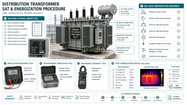
Étape 1 - Vérifier le kVA indiqué sur la plaque signalétique par rapport à la charge connectée. Calculer la charge apparente à partir de la tension et du courant mesurés. Un facteur de charge supérieur à 100% est un signal d'alarme immédiat ; un facteur de charge compris entre 80% et 100% n'est pas automatiquement sûr car la température ambiante, les conditions de refroidissement et la forme de la charge affectent la marge thermique disponible.
Étape 2 - Examiner l'historique des indicateurs thermiques. Relevez l'aiguille de demande maximale sur le WTI ou l'OTI. Une lecture WTI qui a atteint ou dépassé le point de consigne de l'alarme - typiquement 120 °C pour les unités homologuées ONAN selon IEC 60076-2 - confirme qu'une contrainte thermique s'est produite, même si la charge actuelle semble normale.
| Métrique | Acceptable | Enquêter | Action requise |
|---|---|---|---|
| KVA de pointe comme % de la plaque signalétique | <= 100% | 100?120% | > 120% |
| Durée des pics supérieurs à 100% | < 15 min/jour | 15?60 min/jour | > 60 min/jour ou récurrence quotidienne |
| Facteur de charge (kVA moyen / kVA nominal) | <= 75% | 75?90% | > 90% |
| Rapport pic/moyenne | < 1.5 | 1.5?2.0 | > 2.0 |
Un transformateur peut être correctement chargé et exempt de distorsion harmonique et pourtant surchauffer si son système de refroidissement ne peut pas dissiper la chaleur assez rapidement. La défaillance du refroidissement est l'une des causes fondamentales les plus faciles à traiter, car le défaut est généralement visible, mesurable et corrigeable avant que l'isolation des enroulements ne se dégrade.
| Classe de refroidissement | Moyen d'enroulement | Circulation | Bonne performance dans les cas suivants | Devient risqué lorsque |
|---|---|---|---|---|
| ONAN / ON | Huile minérale | Convection naturelle | Sites à faible maintenance, charge stable | Ambiance > 40 °C ou cycles de charge élevés |
| ONAF / OF | Huile minérale | Air forcé (ventilateurs) | Capacité de surcharge modérée nécessaire | Les ventilateurs fonctionnent silencieusement ou les filtres se bouchent |
| OFAF | Huile minérale | Huile forcée + air forcé | Charge continue élevée, encombrement réduit | Les joints de la pompe à huile vieillissent ou les capteurs de débit sont absents. |
| ODAF / OD | Huile dirigée | Huile + air dirigés forcés | Transformateurs de puissance de grande taille, marges thermiques étroites | La cavitation de la pompe ou l'obstruction des conduits d'huile ne sont pas détectées. |
| ANAN / AN | Type sec, air | Convection naturelle | Intérieur, emplacements sensibles au feu | La ventilation du boîtier est restreinte ou la température ambiante augmente |
| ANAF / AF | Type sec, air | Air pulsé | Intérieur avec charge variable | La défaillance du ventilateur ou l'obstruction du conduit provoque une augmentation rapide du point chaud. |
Radiateurs et ailettes de refroidissement (ONAN/ONAF) : Les ailettes obstruées par la poussière, les éclaboussures de peinture ou la croissance biologique réduisent la surface effective. Critère de réussite : les passages d'ailettes sont visuellement dégagés ; le balayage IR montre un gradient de température uniforme de haut en bas de chaque groupe de radiateurs. Indicateur d'échec : une ou plusieurs sections du radiateur sont nettement plus froides que les sections adjacentes sur le balayage IR, ce qui indique un blocage du flux d'huile.
Ventilateurs de refroidissement (ONAF/ANAF) : Une défaillance du moteur du ventilateur, une rotation inversée après entretien ou des roulements grippés réduisent le débit d'air sans déclencher d'alarme en l'absence de contrôle du courant. Mesurer le débit d'air à la sortie du ventilateur à l'aide d'un anémomètre ; une valeur inférieure à 80% du CFM nominal justifie une enquête.

Les harmoniques augmentent les pertes sans augmenter le courant de charge à fréquence fondamentale que la plupart des relais de protection surveillent. Un transformateur fonctionnant à 70% du kVA nominal peut encore surchauffer si la charge est riche en harmoniques, et un ampèremètre standard ne révélera pas le problème.
| Paramètre | Facteur K (IEEE C57.110) | Facteur-K (IEC 61378 / BS 7821) |
|---|---|---|
| Origine | Amérique du Nord | Europe / Régions CEI |
| Objectif | Évaluer un nouveau transformateur pour une charge harmonique connue | Dératisation d'un transformateur existant |
| Exposant des pertes par effet de Foucault | 2.0 (conservateur) | 1,7 (calculé de manière empirique) |
| Sortie | Multiplicateur sans dimension ; coefficient K du transformateur >= K calculé | Appliqué au kVA nominal pour obtenir la capacité déclassée |
| Où il gagne | Spécification de nouveaux transformateurs pour les charges VFD ou UPS | Déterminer si un transformateur standard existant est adéquat |
| Où cela devient risqué | S'appliquant à un transformateur non construit selon la norme IEEE C57.110 | Utilisation sans données harmoniques mesurées |
Déclassement pratique à l'aide du Facteur-K : kVA dérivé = kVA nominal / Facteur-K. Un facteur-K de 1,15 signifie que le transformateur doit être considéré comme ayant 87% de sa capacité nominale.
Pincez des sondes de courant sur tous les conducteurs de phase au secondaire du transformateur ; mesurez les trois phases simultanément.
| Mesures | Acceptable | Enquêter | Action requise |
|---|---|---|---|
| THD-I | < 8% | 8?15% | > 15% |
| Harmonique individuelle (dans n'importe quel ordre) | < 5% de I1 | 5?10% | > 10% |
| Rapport entre le courant neutre et le courant de phase | < 0.5 | 0.5?1.0 | > 1.0 |
| Facteur-K | < 1.05 | 1.05?1.20 | > 1.20 |
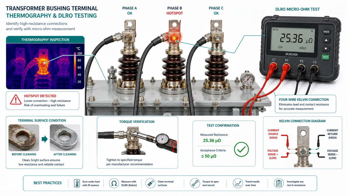
Les connexions desserrées ou corrodées sont parmi les causes de surchauffe les plus sous-diagnostiquées. Une cosse boulonnée qui s'est relâchée, ne serait-ce que de quelques milli-ohms, peut dissiper suffisamment de chaleur pour carboniser l'isolation environnante, alors que la charge nominale reste dans les limites prévues et que le système de refroidissement ne présente aucune anomalie.
| Condition préalable à l'analyse | Exigence |
|---|---|
| Charge au moment de l'analyse | >= 40% du courant nominal ; documenter la charge réelle |
| Temps de trempage minimum à la charge | 30 minutes avant le balayage |
| Vitesse du vent | < 3 m/s |
| Réglage de l'émissivité | 0,90-0,95 pour le cuivre ou l'aluminium oxydé ; 0,85 pour l'acier peint |
| Sensibilité de la caméra | <= 0,1 °C NETD ; détecteur minimum 320×240 |
| ΔT au-dessus de la phase de référence ou de l'ambiance | Sévérité | Action |
|---|---|---|
| 1-3 °C | Défaut possible | Re-scanner à la prochaine occasion ; surveiller la tendance |
| 4-15 °C | Défaut confirmé | Programmer la réparation dans les 30 jours |
| > 15 °C | Défaut grave | Mettre hors tension ou réduire la charge ; réparer avant de revenir à la pleine charge. |
| Type de connexion | Acceptable | Enquêter | Rejeter / Remédier immédiatement |
|---|---|---|---|
| Plaque à douilles (HV, >= 15 kV) | < 10 µΩ | 10-50 µΩ | > 50 µΩ |
| Plaque à douille (BT, < 1 kV) | < 15 µΩ | 15-60 µΩ | > 60 µΩ |
| Cosse de câble à la barre collectrice, boulonnée | < 20 µΩ | 20-100 µΩ | > 100 µΩ |
| Connexion de la bande de terre | < 25 µΩ | 25-100 µΩ | > 100 µΩ |
| Jeu de doigts de contact OLTC (par phase) | Selon les spécifications du fabricant ±20% | > 20% au-dessus des spécifications | > 50% au-dessus des spécifications |
Le flux de travail en quatre étapes suivant ordonne les décisions en fonction du coût et de la probabilité des preuves, en commençant par les observations qui ne nécessitent pas d'interruption et en progressant vers les tests qui en nécessitent une.
Historique de l'entretien : Date du dernier échantillon d'huile et des résultats de la DGA ; date de la dernière inspection du système de refroidissement ; toute augmentation récente de la charge ou ajout de charges non linéaires sur le bus.
Conditions environnementales : Température ambiante par rapport au plafond nominal de la classe de refroidissement du transformateur ; altitude supérieure à 1 000 m ; accumulation de poussière sur les ailettes du radiateur ; humidité élevée récente ou antécédents d'inondation.
| Priorité | Cause profonde | Action immédiate (dans les 24 heures) | Court terme (dans les 30 jours) | Long terme |
|---|---|---|---|---|
| 1 - Critique | Défaut de contact avec ΔT > 40 °C au niveau de la douille ou du changeur de prise | Mettre hors tension ; réparer avant de remettre sous tension | Étude de la résistance de contact complète ; DGA pour les sous-produits de l'arc électrique | Établissement d'une thermographie et d'une résistance de contact de référence ; révision de l'intervalle d'inspection |
| 2 - élevé | Surcharge > 120% en continu | Réduction de la charge ; activation de tous les niveaux de refroidissement disponibles | Installer des compteurs pour suivre la croissance de la charge | Examen des prévisions de charge ; mise à niveau ou transformateur parallèle |
| 2 - élevé | Tous les ventilateurs sont inopérants | Réduction manuelle de la charge à 60-70% de la plaque signalétique ; réparation du ventilateur de secours | Remplacer les composants défectueux ; inspecter le circuit de contrôle | Mise en place d'une surveillance de l'état du système de refroidissement avec alarme à distance |
| 3 - Élevé | Dépassement du facteur K | Déclasser le transformateur jusqu'à la limite de sécurité du facteur K | Mesurer le spectre harmonique à toutes les charges principales | Remplacer l'appareil par un appareil de puissance appropriée ou installer un dispositif de réduction des harmoniques. |
| 4 - Modéré | Radiateur simple bloqué ou panne partielle du ventilateur | Nettoyer ou remettre en état la section de refroidissement concernée | Programme complet d'inspection et de nettoyage des radiateurs | Intervalles de maintenance spécifiques à l'environnement en fonction du taux de contamination |
| 5 - Routine | Dépassement de la température ambiante pendant le pic saisonnier | Confirmer que la charge ne dépasse pas les valeurs nominales corrigées ; surveiller en permanence. | Évaluer le refroidissement d'appoint | Inclure le déclassement ambiant dans la planification annuelle de la capacité |
Contexte du site : Un transformateur de 1 000 kVA, 13,2 kV / 480 V, refroidi par l'ONAF et desservant l'atelier de production d'une usine de fabrication à forte intensité de VFD, a reçu une alarme WTI à 118 °C lors d'un pic de production en milieu d'après-midi.
Observations initiales : Le courant de charge mesuré au secondaire était d'environ 880 kVA-88% par rapport à la valeur nominale de la plaque signalétique. La température ambiante était de 36 °C, ce qui correspond au plafond de la classe de refroidissement de 40 °C du transformateur.
Contrôle du refroidissement : Deux des quatre ventilateurs de refroidissement tournaient. Le contacteur d'un troisième ventilateur s'est déclenché en raison d'une surcharge thermique. Le quatrième ventilateur avait été rebranché en sens inverse après le remplacement récent de son moteur, ce qui réduisait sa contribution effective au débit d'air. Le débit d'air total mesuré était de 62% de CFM nominal combiné pour les quatre unités.

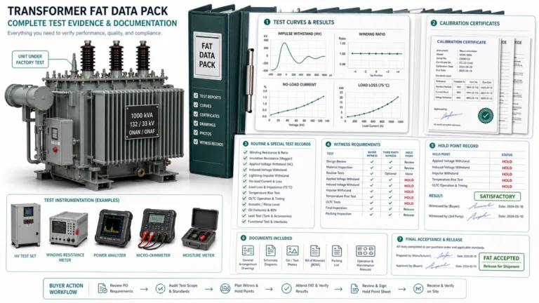
Lorsqu'un transformateur a des antécédents de surchauffe documentés, un remplacement à l'identique résout rarement le problème. Le processus d'achat doit s'attaquer aux causes profondes identifiées lors du dépannage avant qu'un bon de commande ne soit émis.
| Critère | Minimum acceptable | Drapeau rouge |
|---|---|---|
| Augmentation de la température | Augmentation de 80 °C ou 115 °C pour le type sec ; classe confirmée | Augmentation de 150 °C pour une unité classée K sans justification thermique |
| Documentation sur le facteur K | Rapport de test d'usine inclus | Facteur K sur la plaque signalétique uniquement, pas de données d'essai |
| Documentation sur les classes de refroidissement | ONAN/ONAF/OFAF clairement indiqué avec la capacité nominale à chaque étape | “Auto-refroidissement” sans modèle thermique |
| Données sur les pertes | Pertes à vide et en charge au courant nominal fournies | Pourcentage d'efficacité uniquement |
| Base du modèle thermique | IEEE C57.91 ou IEC 60076-7 déclaré | Pas de modèle thermique fourni |
| Étendue de la garantie | Couvre la défaillance de l'isolation du bobinage, et pas seulement les défauts de fabrication | Exclut la surcharge sans définir le seuil |
| Engagement en matière de pièces de rechange | Des bobinages ou des composants de refroidissement de remplacement sont disponibles dans les délais indiqués. | Conception sur mesure sans engagement de pièces détachées |

Utilisez ces références XBRELE pour relier la décision sur le terrain au produit correct, au test et au flux de travail de l'approvisionnement : Page produit XBRELE, Gamme de disjoncteurs à vide XBRELE, Guide de notation de la VCB, Liste de contrôle pour l'acceptation du TFA/TSA par le VCB, Gamme de transformateurs de distribution d'énergie XBRELE.
Pour le contexte de la méthode externe, comparez la procédure du site avec la procédure publique. Page des normes IEEE C37.09 et appliquer le manuel de l'équipementier et les spécifications du projet pour l'équipement fourni.
Exemple de terrain : lors d'une inspection de service, une phase a été mesurée en dehors de sa ligne de base de mise en service, alors que les deux autres phases sont restées stables. L'équipe a répété la mesure avec des fils vérifiés, a contrôlé la synchronisation et la course du contact, et a utilisé la divergence mesurée pour distinguer un problème de pression de contact d'un problème générique de nettoyage de surface.
Dans les bâtiments commerciaux, la distorsion harmonique provenant des variateurs de vitesse, des systèmes d'alimentation sans interruption et des alimentations à découpage est la cause la plus fréquemment négligée. La surcharge est souvent suspectée en premier, mais une mesure de la qualité de l'énergie révèle souvent qu'un transformateur fonctionnant à 70-80% du kVA nominal surchauffe encore parce que ses pertes par courants de Foucault sont élevées en raison d'un THD-I élevé.
Pour les transformateurs de distribution en service industriel ou commercial standard, un contrôle de la résistance de contact à toutes les bornes externes tous les 3 ans est une base raisonnable. Les transformateurs utilisés dans des environnements soumis à de fortes vibrations, dans des zones côtières ou humides, ou dans des applications soumises à des cycles de charge fréquents, doivent faire l'objet d'un contrôle annuel.
Pas indéfiniment. À une charge de 110% dans un environnement standard de 40 °C, la norme IEEE C57.91 indique que la consommation de la durée de vie de l'isolation double approximativement par rapport à la charge nominale.
Un facteur K indique qu'un transformateur a été conçu avec des enroulements renforcés et un coefficient de perte par courants de Foucault réduit pour gérer les charges riches en harmoniques. Les transformateurs de distribution standard sont classés K-1 ; les unités classées K-4, K-13 et K-20 sont progressivement plus tolérantes aux courants harmoniques.
Rétablissez le fonctionnement complet du ventilateur et observez si le relevé WTI revient à la normale au même niveau de charge dans les 2 à 4 heures qui suivent. Si la température chute de manière significative, la défaillance du système de refroidissement est confirmée comme étant la cause principale de la panne.
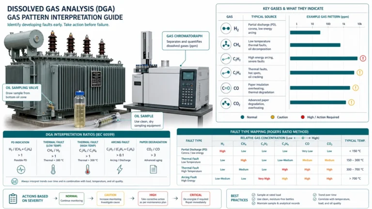
Le méthane (CH4) et l'éthylène (C2H4) sont les principaux marqueurs de la décomposition thermique du pétrole à des températures modérées (150-500 °C). L'acétylène (C2H2) apparaît à des températures supérieures à 700 °C et est associé à des arcs électriques ou à des échauffements localisés très intenses.
Le remplacement devient la décision la plus économique lorsque deux ou plusieurs des éléments suivants sont réunis : l'unité a connu plusieurs alarmes thermiques au cours d'une période de trois ans malgré des mesures correctives ; les résultats de la DGA montrent des concentrations soutenues ou croissantes de gaz de décomposition thermique ; la résistance de contact des composants internes ne peut être rétablie selon les spécifications sans un rembobinage complet ; l'environnement de charge a changé au point que l'unité existante ne peut pas être déclassée de manière adéquate ; ou l'unité a dépassé la durée de vie recommandée par le fabricant et les pièces de rechange ne sont plus disponibles. Un remplacement à l'identique doit toujours être précédé de la liste de contrôle des achats ci-dessus afin d'éviter de répéter le même mode de défaillance.