Vous avez besoin des spécifications complètes ?
Téléchargez notre catalogue de produits 2025 pour obtenir les schémas détaillés et les paramètres techniques de tous les composants des appareillages de commutation.
Obtenir le catalogueTéléchargez notre catalogue de produits 2025 pour obtenir les schémas détaillés et les paramètres techniques de tous les composants des appareillages de commutation.
Obtenir le catalogueTéléchargez notre catalogue de produits 2025 pour obtenir les schémas détaillés et les paramètres techniques de tous les composants des appareillages de commutation.
Obtenir le catalogue
Les défaillances des essais de réception en usine des disjoncteurs à vide sont rarement surprenantes. Elles sont l'extrémité visible d'une chaîne qui commence dès le bon de commande. Ce guide explique comment diagnostiquer les non-conformités au stade de la réception en usine, lire les rapports d'essai à la recherche de défauts cachés, rédiger des clauses qui préviennent les défaillances et clôturer les NCR sans perdre de temps.
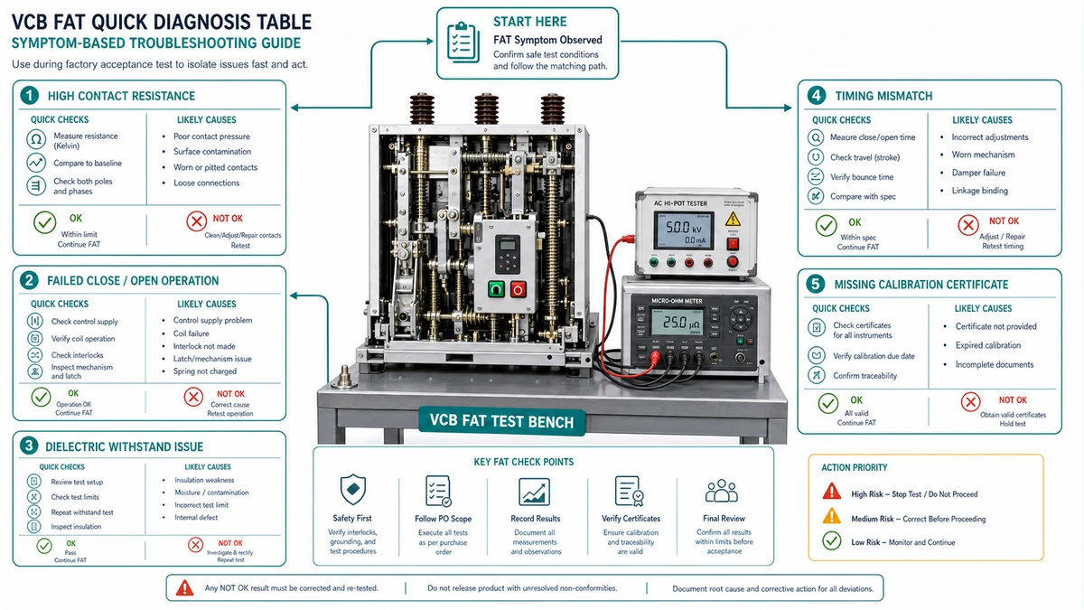
Utilisez ce tableau au début de toute session de témoignage FAT ou lors de l'examen d'un rapport FAT soumis. Il permet d'associer les symptômes les plus courants à un premier test, à une cause première probable et à l'action suivante.
| Symptôme | Premier test | Cause première probable | Action suivante |
|---|---|---|---|
| Résistance de contact supérieure à la limite | Re-mesure avec injection de 100 A DC (DLRO) par pôle | Contacts usés, couple de serrage insuffisant, contamination de la surface | Déclarer un cas de non-conformité ; demander un remaniement et un nouveau test complet |
| Défaillance de la résistance diélectrique | Vérifier l'absence de contamination, d'humidité et de lignes de fuite | Pénétration de l'humidité, suivi de la surface, dégagement incorrect | Rejet inconditionnel ; aucun UAI n'est autorisé |
| Heure de fermeture ou d'ouverture en dehors de l'orchestre | Réessai à 85%, 100% et 110% de la tension de commande nominale | Tension du ressort incorrecte, défaut du dashpot, faible tension de commande | Ajuster le mécanisme ; tester à nouveau la séquence de synchronisation complète |
| Différence de temps entre les pôles > 3 ms | Extraction des temps de pôles individuels à partir de la sortie de l'analyseur de temps | Chargement inégal des ressorts, usure du mécanisme des pôles | Augmenter le NCR ; comparer avec la tolérance du PO, et pas seulement avec la feuille de données |
| Résistance d'isolation inférieure à 1 000 Mohm | Nouveau test après 24 heures de séchage à température ambiante | Absorption d'humidité pendant le stockage ou le transport | Échec conditionnel ; enquête avant acceptation |
| La bobine de déclenchement ne fonctionne pas à 85% Vc | Mesurer la résistance de la bobine ; comparer avec la plaque signalétique | Mauvaise spécification de la bobine, défaut d'enroulement, inadéquation de la tension de commande | Comparer avec la courbe de décharge de la batterie ; remplacer la bobine si la portée est insuffisante. |
| Certificat d'essai ou section manquant | Vérifier le registre d'approbation de l'AQ et l'enregistrement des séquences de test | Processus d'assurance qualité incomplet, test annulé sans avis de déviation | Documenter la non-conformité en tant que documentation ; ne pas accepter le rapport comme définitif |
| Non concordance des données de la plaque signalétique | Comparer la plaque signalétique avec les lignes du bon de commande | Erreur d'écriture, mauvais lot d'étiquettes appliqué | Demander un NCR ; corriger avant l'expédition afin d'éviter les erreurs de réglage des relais sur le site. |
Les résultats FAT contestés sont souvent dus à un mauvais instrument, à un étalonnage périmé ou à un mauvais document d'acceptation. Ce tableau définit l'instrument correct et la source de référence pour chaque mesure critique.
| Mesures | Instrument requis | Spécifications minimales | Source d'acceptation | Les raisons de l'échec du mauvais outil |
|---|---|---|---|---|
| Résistance de contact | Micro-ohmmètre (DLRO) | Injection de 100 A DC | Rapport d'essai du type de fabricant, puis limite de l'OP | Les ohmmètres à faible courant manquent la résistance du film sur les contacts plaqués argent |
| Résistance de l'isolation | Testeur de résistance d'isolation | 2,5 kV ou 5 kV DC selon IEC 62271-1 | IEC 62271-1 Tableau 1 ; PO si plus strict | Les testeurs 500 V ne peuvent pas solliciter l'isolation à moyenne tension de manière adéquate |
| Résistance à la fréquence industrielle | Testeur de courant alternatif (AC hipot) | Par classe de tension nominale (par exemple, 28 kV pour 12 kV VCB) | IEC 62271-100 Tableau 1 ; classe de tension PO | Le hipot à courant continu n'est pas un substitut direct ; des modes de défaillance différents s'appliquent. |
| Calendrier (fermeture/ouverture/reclôture) | Analyseur de disjoncteur dédié | Résolution <= 0,1 ms | Bande d'essai du fabricant ; tolérance de l'OP si elle est indiquée | Les montages d'oscilloscopes sans transducteurs calibrés introduisent une erreur systématique |
| Course et surcourse mécaniques | Capteur de déplacement linéaire ou comparateur calibré | Résolution de +/- 0,1 mm | Rapport d'essai de type du fabricant | Les mesures à la règle sur les pièces mobiles ne sont pas répétables |
| Intégrité du vide | Tenue aux fréquences de puissance pour les contacts ouverts | Selon IEC 62271-1 pour la classe de tension nominale | IEC 62271-100 ; pas de zone marginale | Il n'y a pas de substitut direct sur le terrain ; ce test est une approximation de l'état de la bouteille sous vide. |
| Décharge partielle | Détecteur de DP selon IEC 60270 | Sensibilité selon PO ou IEC 62271-1 | Limite d'acceptation de l'OP en pC | Les testeurs hipot standard ne détectent pas la MP ; un instrument séparé est nécessaire. |
| Synchronisation des contacts auxiliaires | Analyseur de disjoncteur avec canal auxiliaire | Résolution <= 0,1 ms | Spécification de l'interface du relais PO | Une temporisation auxiliaire incorrecte affecte le verrouillage de la protection |
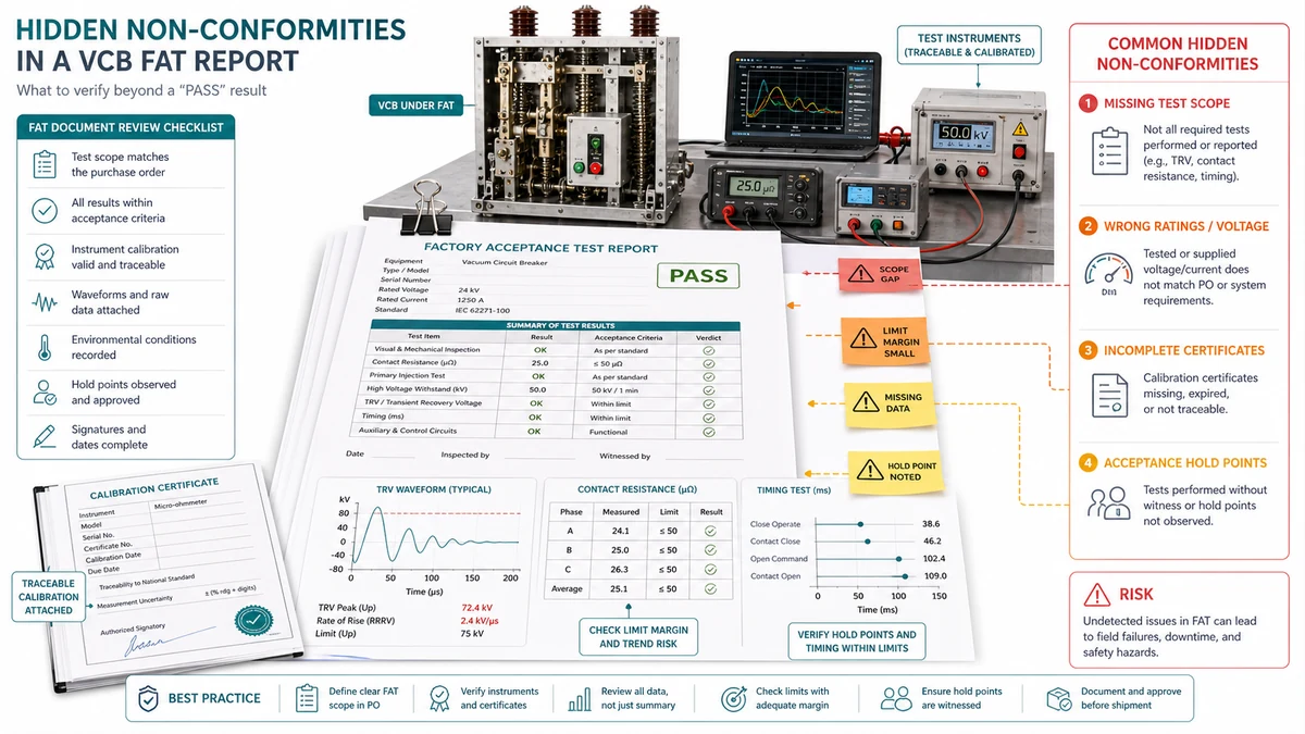
Un rapport qui passe en surface peut encore contenir des non-conformités intégrées : des valeurs qui dépassent techniquement le seuil d'acceptation, mais qui signalent une unité fonctionnant près de sa limite. Traitez le rapport comme une source de données structurées et non comme un certificat de réussite ou d'échec.
Étape 1 : Vérifier l'exhaustivité avant de lire les résultats. Confirmez que le rapport contient les essais diélectriques, la résistance de contact par pôle, l'enregistrement de l'endurance mécanique, la tension de prise minimale pour les bobines de fermeture et de déclenchement, la résistance d'isolation, les résultats du chronométrage et la confirmation de l'intégrité du vide. Une section manquante signifie que l'essai n'a pas été effectué ou qu'il n'y a pas eu de témoin.
Étape 2 : Référence croisée avec la révision correcte de la norme. La norme CEI 62271-100 et la norme IEEE C37.09 ont des critères d'acceptation différents pour le même paramètre. Si votre commande spécifie l'un de ces critères et que l'usine a testé l'autre, le résultat peut être non conforme même si le nombre semble acceptable.
| Test | Limite d'acceptation des PO | Valeur du rapport | Marge | Statut |
|---|---|---|---|---|
| Résistance de contact (par pôle) | <= 50 micro-ohms | 47 micro-ohms | 6% | Risque latent |
| Heure de fermeture | 50-60 ms | 58 ms | 3.3% | Risque latent |
| Dispersion inter-pôles (proche) | <= 3 ms | 6 ms | – | Non-conformité |
| Tension de déclenchement minimale | <= 70% Vc | 68% Vc | 2.9% | Risque latent |
| Résistance de l'isolation | >= 1 000 Mohm | 1 200 Mohm | 20% | Acceptable |
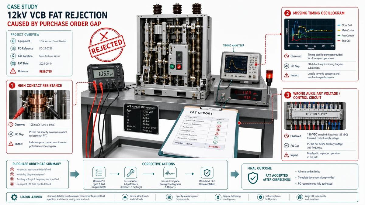
Un projet de sous-station de service public spécifiait douze disjoncteurs à vide de 12 kV pour le service de protection de la ligne d'alimentation. Le bon de commande faisait référence à la norme CEI 62271-100 et indiquait un courant de coupure de court-circuit nominal de 25 kA.
Résistance de contact hors spécifications. Les valeurs mesurées sur deux unités allaient de 68 à 74 micro-ohms, alors que la limite interne du fabricant était de 60 micro-ohms. Comme le bon de commande ne comportait pas de plafond de résistance de contact explicite ni de procédure FAT référencée, le rejet a finalement été émis au motif que l'écart dépassait la fiche technique publiée par le fabricant lui-même. Le litige a retardé la signature de l'acceptation de onze jours.
Tension de fonctionnement de la bobine de déclenchement hors tolérance. Le bon de commande spécifiait des bobines de déclenchement de 110 V CC, mais ne précisait pas la plage de tension acceptable. Les bobines livrées fonctionnaient entre 88 V CC et 132 V CC. Le système de protection du projet a été conçu pour une tension de batterie minimale de 80 V CC dans des conditions de défaillance, ce qui est en dehors de la fenêtre de fonctionnement garantie de la bobine. Le décalage a été découvert au FAT, et non lors de l'examen de la coordination des relais.
| Non-conformité | Cause directe | Écart entre les PO |
|---|---|---|
| Résistance de contact élevée | Variation de la qualité de l'assemblage | Aucune valeur de résistance maximale n'est indiquée dans le PO ou dans la procédure FAT référencée. |
| Inadéquation de la tension de la bobine de déclenchement | La conception de la protection n'est pas coordonnée avec la passation de marchés | Absence de bande de tolérance de tension ; la tension de fin de décharge de la batterie n'est pas référencée. |
| Mauvaise classe d'endurance | Documents contradictoires | L'accord verbal n'est pas pris en compte dans le PO émis ; M1 est sélectionné par défaut. |
Citer la norme CEI 62271-100 dans un bon de commande est nécessaire mais pas suffisant. Cette norme laisse aux fabricants une grande latitude en ce qui concerne la séquence, les intervalles d'étalonnage et les seuils d'acceptation des résultats limites.
Tenue diélectrique. Éviter : “Les essais diélectriques doivent être effectués conformément à la norme CEI 62271-100.” Utiliser plutôt : “Les essais de tenue aux fréquences de puissance doivent être effectués à [X] kV eff. pendant 60 secondes sur les contacts ouverts et entre chaque pôle et la terre, à une température ambiante comprise entre 10°C et 40°C et à une humidité relative ne dépassant pas 75%. La décharge partielle doit être mesurée à [X] kV et ne doit pas dépasser [Y] pC. Les conditions ambiantes au moment de l'essai doivent être consignées dans le rapport d'essai.”
Calendrier et déplacements. Éviter : “Les essais de fonctionnement mécanique doivent vérifier le bon fonctionnement”. Utiliser plutôt : “Le temps de fermeture du contact doit être de [X +/- Y] ms. Le temps d'ouverture du contact doit être de [A +/- B] ms. Toutes les mesures doivent être effectuées à la tension de commande nominale et répétées à 85% et 110% de la tension de commande nominale. Les résultats individuels doivent être enregistrés ; la moyenne des résultats n'est pas acceptable en lieu et place des mesures individuelles”.”
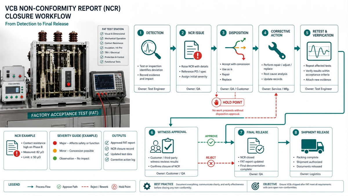
Lorsqu'une non-conformité est signalée, deux pressions concurrentes s'exercent sur l'horloge : résoudre correctement le défaut et protéger la date de livraison. Chaque rapport de non-conformité doit passer par quatre étapes bien définies.
Détection et documentation. L'inspecteur établit un rapport de non-conformité formel au point de défaillance, en consignant le test effectué, le résultat mesuré, le critère d'acceptation applicable, ainsi que la date et l'heure de la détection. Les accords verbaux ne constituent pas un NCR.
Décision de disposition. Le représentant qualité du fabricant et l'inspecteur de l'acheteur attribuent conjointement un code de disposition.
| Code de disposition | Signification | Quand s'applique-t-il ? |
|---|---|---|
| Utilisation en l'état (UAI) | Accepter sans retravailler | L'écart se situe dans les limites de la tolérance technique ; une justification écrite est requise. |
| Remaniement | Corriger et tester à nouveau | Le défaut peut être corrigé à l'usine dans le cadre du programme d'essai. |
| Réparation | Correction non standard ; nécessite l'approbation de l'ingénieur | Défaut structurel pour lequel une reprise standard n'est pas possible |
| Retour au fournisseur | Rejet au niveau du composant | Sous-composant défectueux d'origine externe |
| Mise au rebut/remplacement | Unité ou ensemble condamné | Le défaut compromet l'intégrité diélectrique ou la sécurité mécanique |
| Type de non-conformité | Disposition acceptable | Disposition risquée | Notes |
|---|---|---|---|
| Résistance de contact supérieure à la limite | Retravailler + retester | UAI | Une résistance élevée indique une contamination de la surface ou une force de contact insuffisante. |
| Temps de déclenchement en dehors de la bande IEC | Remise en état (ajustement du mécanisme) + nouveau test | UAI | Les écarts de temps affectent la coordination de la protection ; les ajustements sur le terrain sont rarement possibles après l'installation. |
| Défaillance de la résistance diélectrique | Retravail + séquence complète de retests | UAI ou navire conditionnel | Pas d'exception ; un nouveau contrôle partiel après une retouche est insuffisant. |
| Rapport CT incorrect | Retour au fournisseur + remplacement | UAI | Les erreurs de rapport de TC affectent la précision du comptage et de la protection sur l'ensemble du système. |
| Documentation incomplète | Action corrective (aucun nouveau test n'est nécessaire) | Envoi conditionnel sans délai | Fixer une date limite stricte ; les lacunes en matière de documentation s'aggravent au cours de la mise en service |
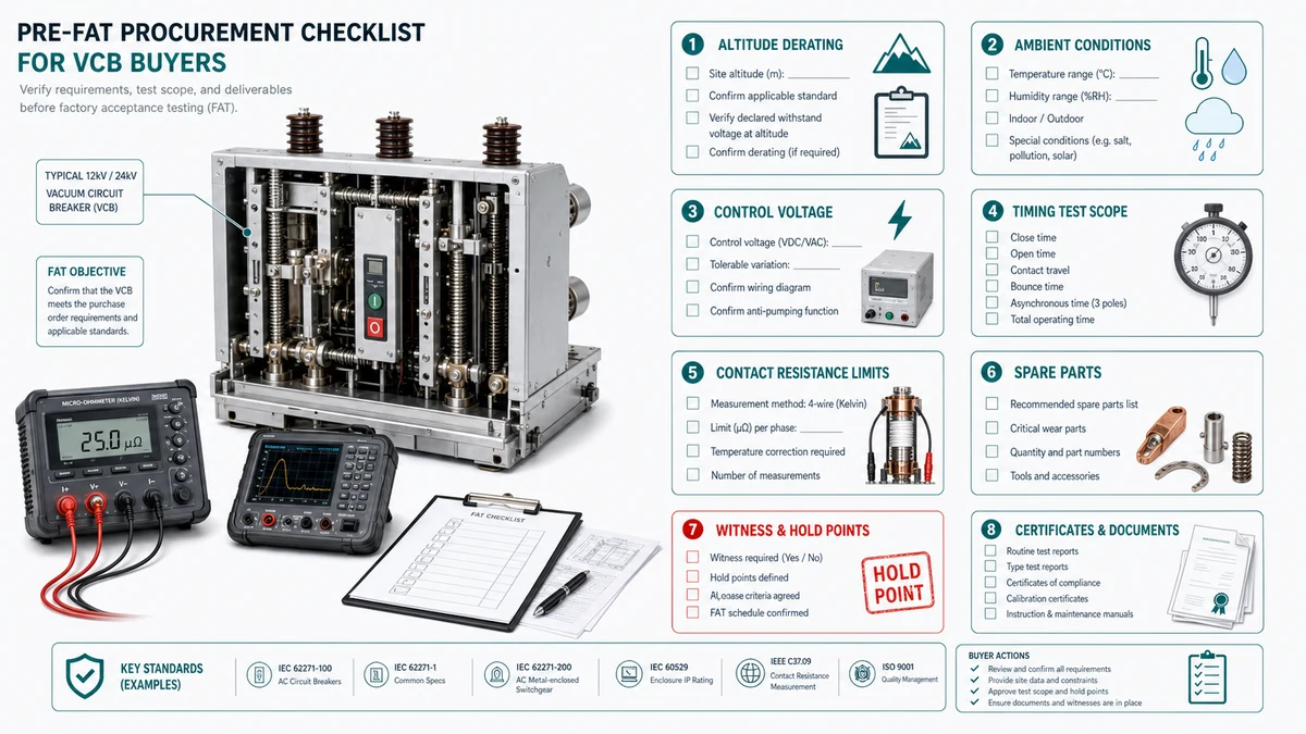
Lorsqu'un ingénieur témoin arrive sur le banc d'essai du fabricant, la possibilité de corriger les lacunes des spécifications sans incidence sur les coûts et le calendrier s'est largement refermée. Vérifiez ces variables au moins six semaines avant la date prévue pour le test FAT.
Correction de l'altitude et du diélectrique. Si le site d'installation est situé au-dessus de 1 000 m, le PO doit indiquer l'altitude réelle afin que le fabricant applique le facteur de déclassement correct conformément à la norme CEI 62271-1. Les FAT réalisés dans des conditions d'usine au niveau de la mer aboutiront à des valeurs nominales inadéquates une fois que le disjoncteur sera mis sous tension en altitude.
Classe de température et d'humidité ambiantes. Les sites tropicaux ou côtiers où l'humidité est élevée de façon continue nécessitent une classe d'humidité définie et, dans de nombreux cas, des spécifications de chauffage anti-condensation. Si le PO omet la classification de l'humidité, le FAT ne comprendra pas de vérification de l'endurance à l'humidité adaptée à votre environnement.
Utilisez ces références XBRELE pour relier la décision sur le terrain au produit correct, au test et au flux de travail de l'approvisionnement : Page produit XBRELE, Gamme de disjoncteurs à vide XBRELE, Guide de notation de la VCB, Liste de contrôle pour l'acceptation du TFA/TSA par le VCB, Guide de test de la résistance de contact en micro-ohms.
Pour le contexte de la méthode externe, comparez la procédure du site avec la procédure publique. Page des normes IEEE C37.09 et appliquer le manuel de l'équipementier et les spécifications du projet pour l'équipement fourni.
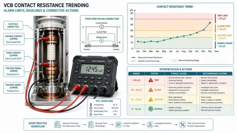
Exemple de terrain : lors d'une inspection de service, une phase a été mesurée en dehors de sa ligne de base de mise en service, alors que les deux autres phases sont restées stables. L'équipe a répété la mesure avec des fils vérifiés, a contrôlé la synchronisation et la course du contact, et a utilisé la divergence mesurée pour distinguer un problème de pression de contact d'un problème générique de nettoyage de surface.
Une non-conformité FAT est un résultat mesuré, un document manquant ou une vérification fonctionnelle échouée qui s'écarte de la spécification convenue avant que le disjoncteur ne quitte l'usine du fabricant. Il peut s'agir d'un problème électrique (résistance de contact, temporisation, tenue diélectrique), mécanique (course, fonction de verrouillage, crémaillère) ou documentaire (certificats manquants, données de la plaque signalétique incorrectes).
Les défaillances de tenue diélectrique et les écarts de temporisation présentent le risque le plus élevé après l'installation, car ils affectent directement la capacité du disjoncteur à interrompre le courant de défaut dans le temps nominal. Les défaillances de la résistance de contact qui sont acceptées telles quelles entraînent une surchauffe au courant nominal au fil du temps.
L'AUI n'est autorisée que pour les écarts qui se situent dans les limites de la tolérance technique et qui sont étayés par une justification technique écrite signée par un ingénieur responsable. L'AUI n'est pas acceptable pour les échecs des essais diélectriques, les résultats de la résistance de contact en dehors de la tolérance publiée par le fabricant, ou les temps de déclenchement en dehors des limites de la norme CEI 62271-100.
Calculer le taux de marge : Marge (%) = [(Limite - Valeur mesurée) / Limite] x 100. Signaler tout paramètre dont la marge est inférieure à 15% comme une non-conformité latente, même si le rapport indique qu'il a été accepté.
Le rapport doit inclure les résultats numériques individuels pour chaque paramètre mesuré, à côté de la limite d'acceptation spécifiée ; le numéro de série et la référence du certificat d'étalonnage pour chaque instrument utilisé ; la température ambiante, l'humidité et la tension de commande au moment de chaque essai ; le nom et la signature du technicien effectuant chaque essai ; et une indication claire de tout résultat nécessitant un nouvel essai, avec l'enregistrement du résultat initial et du résultat final. Les fiches récapitulatives des réussites et des échecs sont insuffisantes pour servir de référence à la mise en service.
Demandez le projet de procédure FAT, les rapports d'essai de type applicables, le schéma du circuit auxiliaire estampillé et le plan d'inspection et d'essai au moins six semaines avant la date prévue pour l'audition. Si le fournisseur n'est pas en mesure de produire ces documents dans ce délai, il convient de traiter cette situation comme une non-conformité dans le cadre du processus de gestion de la qualité.
Un point d'arrêt signifie que le fabricant ne peut pas passer à l'étape suivante de l'essai sans l'approbation écrite par l'acheteur du résultat de l'étape précédente. Un point témoin signifie que l'acheteur a le droit d'assister à l'essai, mais que l'essai peut se poursuivre si l'acheteur renonce par écrit à sa présence.