Vous avez besoin des spécifications complètes ?
Téléchargez notre catalogue de produits 2025 pour obtenir les schémas détaillés et les paramètres techniques de tous les composants des appareillages de commutation.
Obtenir le catalogue
Téléchargez notre catalogue de produits 2025 pour obtenir les schémas détaillés et les paramètres techniques de tous les composants des appareillages de commutation.
Obtenir le catalogue Téléchargez notre catalogue de produits 2025 pour obtenir les schémas détaillés et les paramètres techniques de tous les composants des appareillages de commutation.
Obtenir le catalogue
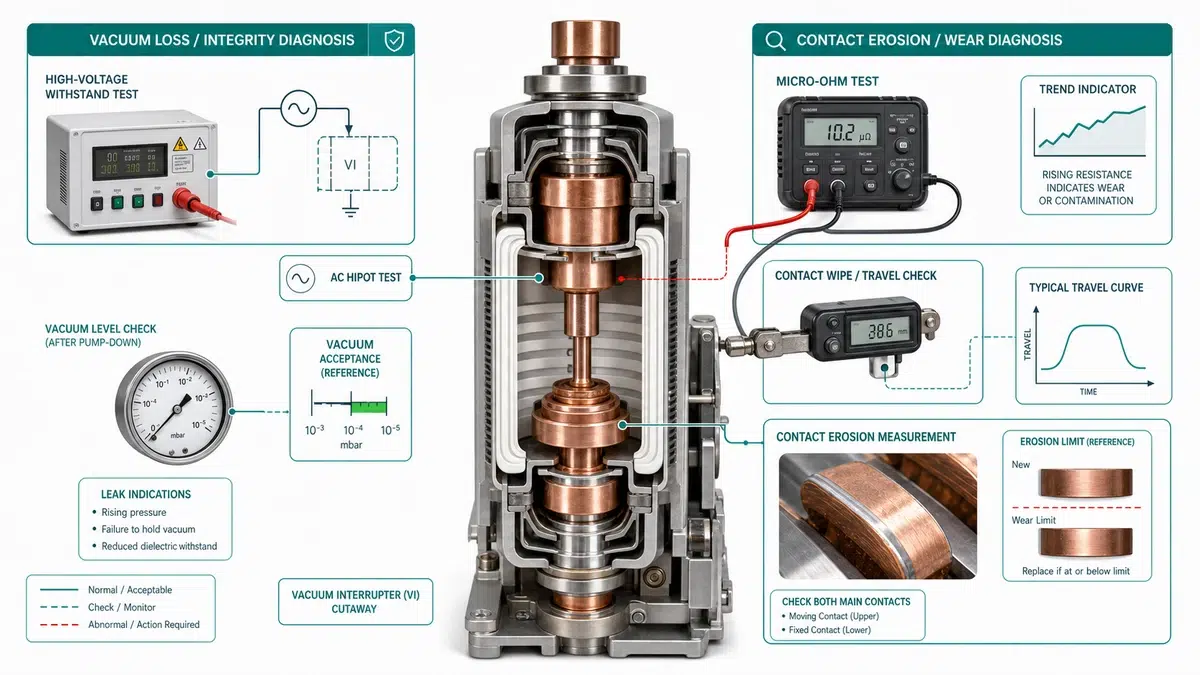
La perte de vide et l'érosion de contact peuvent créer des symptômes similaires dans un disjoncteur à vide, mais il ne s'agit pas de la même défaillance. La perte de vide est une perte d'intégrité diélectrique à l'intérieur de la bouteille scellée du disjoncteur. L'érosion des contacts est une usure mécanique et électrique des faces de contact après la commutation du courant de charge ou du courant de défaut.
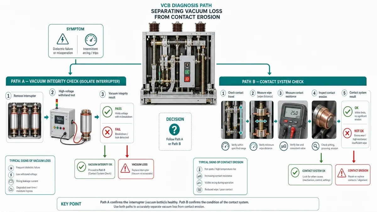
La règle pratique est simple : l'échec d'un test d'intégrité du vide indique qu'il faut remplacer l'interrupteur ; l'érosion du contact doit être confirmée par le déplacement, l'essuyage, l'indicateur d'érosion et la résistance du contact. Ne remplacez pas un disjoncteur complet tant que ces deux modes de défaillance n'ont pas été séparés.
Utilisez ce tableau de dépannage avant de démonter l'assemblage des pôles. Il indique le premier test, la cause première probable et l'action suivante pour les symptômes les plus courants sur le terrain.
| Symptôme | Premier test | Cause première probable | Action suivante |
|---|---|---|---|
| Le pot d'échappement ne fonctionne pas lorsque les contacts sont ouverts | Test d'intégrité sous vide | Perte de vide à l'intérieur de l'interrupteur | Mettre hors service et remplacer l'interrupteur |
| Le pot d'échappement passe, mais la résistance de contact augmente | Test de 100 A micro-ohms | Érosion du contact, contamination ou faible force de contact | Vérifier les déplacements et l'essuyage avant de décider du remplacement |
| L'indicateur d'érosion est à la limite | Inspection mécanique | Contact érosion à la fin de l'allocation | Remplacer l'interrupteur ou l'assemblage des pôles |
| L'espace ouvert est plus court que la valeur OEM | Mesure des déplacements | Usure du contact ou erreur de liaison du mécanisme | Comparer avec la limite de service de l'OEM et ajuster ou remplacer |
| Redémarrage ou interruption retardée du courant | Hi-pot plus record de chronométrage | Perte de vide ou érosion avancée | Exécution d'une séquence de diagnostic complète et examen des données relatives aux événements de relais |
| Pôle chaud pendant le fonctionnement en charge | Image thermique et résistance de contact | Erosion des joints ou des contacts à haute résistance | Serrer/nettoyer d'abord le joint externe, puis retester le chemin de contact. |
La perte de vide signifie que la bouteille d'interruption ne peut plus maintenir l'environnement diélectrique nécessaire à l'extinction de l'arc à courant nul. L'équipe sur le terrain ne peut pas regazer ou réparer la bouteille à vide sur place. Une fois que la perte de vide est confirmée, l'action correcte consiste à remplacer l'interrupteur ou l'ensemble du poteau conformément à la conception de l'équipementier.
Les déclencheurs typiques sont les dommages aux joints, la fatigue des soufflets, la défaillance du joint céramique-métal, les chocs mécaniques ou une longue durée de service combinée à un nombre élevé d'opérations. La défaillance peut rester silencieuse jusqu'à ce qu'un test de résistance ou un événement de commutation expose la marge diélectrique réduite.
La perte de vide ne prouve pas automatiquement que le mécanisme est usé ou que les trois pôles doivent être remplacés. Si un seul pôle échoue au test du vide et que l'équipementier autorise le remplacement d'un seul pôle, les autres pôles ne peuvent rester en service qu'après avoir subi les mêmes contrôles du point haut, de la résistance et de la course.
La valeur de réussite ou d'échec doit provenir du manuel de l'équipementier, de la spécification d'essai du projet ou du contexte des normes applicables. Les normes IEEE C37.09 et IEC 62271-100 fournissent un contexte de méthode d'essai, mais la valeur d'acceptation de service pour un disjoncteur spécifique doit être confirmée par rapport aux données du fabricant.
L'érosion du contact est une perte graduelle de matériau de contact causée par l'arc électrique pendant la commutation de la charge et l'interruption du défaut. Elle réduit l'essuyage des contacts, la force de contact et la course restante. Un disjoncteur peut encore avoir une bonne intégrité de vide alors que ses contacts sont proches de la limite d'usure.
La preuve la plus utile sur le terrain n'est pas un seul chiffre. Combinez la résistance de contact, la course, l'essuyage, l'indicateur d'érosion visible, le compteur d'opérations et l'historique des interruptions de défaut. Un seul relevé de micro-ohm élevé peut provenir de joints externes desserrés ou de surfaces contaminées, il faut donc s'assurer que le chemin de mesure est correct avant de condamner l'interrupteur.
| Preuve | Signal d'érosion de contact | Signal de perte de vide |
|---|---|---|
| Hi-pot à travers les contacts ouverts | Passe généralement jusqu'à ce qu'elle soit gravement endommagée | Défaillance ou forte augmentation des fuites |
| Résistance de contact | Tend souvent à la hausse | Peut être normal à moins que le contact ne soit endommagé |
| Voyage et essuyage | Réduit par rapport au niveau de référence | Généralement normal |
| Indicateur d'érosion | Dans la zone d'alerte ou de remplacement | Peut encore sembler normal |
| Enregistrement du temps | Possibilité de rebond ou de mouvement retardé | Possibilité de redémarrage ou d'interruption en cas d'échec |
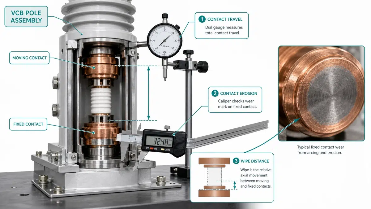
La séquence la plus sûre consiste à confirmer d'abord l'intégrité du vide, puis à vérifier l'usure des contacts et les preuves du mécanisme. Cela évite de perdre du temps à effectuer des contrôles de déplacement détaillés alors que l'interrupteur a déjà échoué à l'essai diélectrique de base.
Toute mesure nécessite une source d'acceptation. Les valeurs génériques des articles ne sont que des références de sélection.
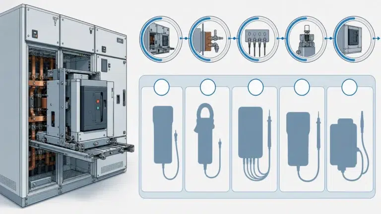
| Outil ou enregistrement | Ce qu'il vérifie | Source d'acceptation |
|---|---|---|
| Testeur de potentiel élevé en courant alternatif ou continu | Intégrité du vide au niveau des contacts ouverts | Manuel OEM, contexte IEEE C37.09, spécification du projet |
| Micro-ohmmètre 100 A | Résistance du chemin de contact principal | Base OEM, enregistrement FAT, tendance en matière de maintenance |
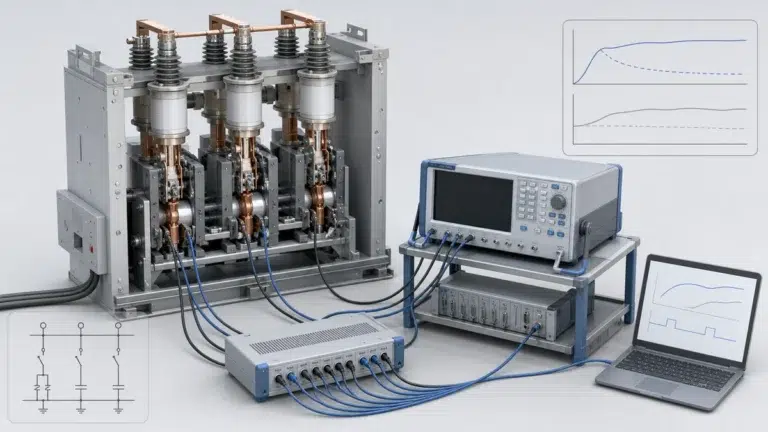
| Analyseur de déplacement ou comparateur | Ouverture de la brèche, essuyage, rebond et course | Courbe de déplacement OEM et limite de service |
| Testeur de résistance d'isolation | Blindage de l'isolation pôle à pôle et phase à phase | Manuel de l'équipementier et spécifications de mise en service |
| Analyseur de temps | Heure d'ouverture, heure de fermeture, rebond, simultanéité | Bande de chronométrage d'origine et enregistrement SAT |
| Compteur d'opérations et journal des événements du relais | Historique des services et décompte des interruptions de service | Registre de maintenance et registre des relais de protection |
Ouvrez les contacts jusqu'à l'écartement spécifié, isolez et mettez à la terre l'équipement, puis appliquez la tension d'essai conformément à la procédure approuvée. Un embrasement, une augmentation du courant de fuite ou une résistance instable suffisent à mettre l'interrupteur hors service. Si l'on soupçonne une contamination superficielle, nettoyer et sécher l'isolation externe conformément à la procédure de l'équipementier avant de répéter l'essai.
Mesurez chaque pôle avec une connexion Kelvin à quatre fils et un courant d'injection suffisant pour obtenir des relevés stables. Enregistrez le courant d'injection, la température ambiante, le numéro de série de l'instrument et la position de la phase. Une phase qui se trouve à plus de 30% au-dessus des deux autres phases mérite d'être inspectée, même si la valeur absolue reste inférieure au maximum OEM.
Mesurer l'entrefer, la course totale, l'essuyage du contact et le rebond. Si la course est normale mais que la résistance est élevée, il faut examiner l'état de la surface de contact et les articulations externes. Si la course et la résistance sont toutes deux en dehors des limites, l'érosion du contact est le défaut dominant et le remplacement doit être planifié.
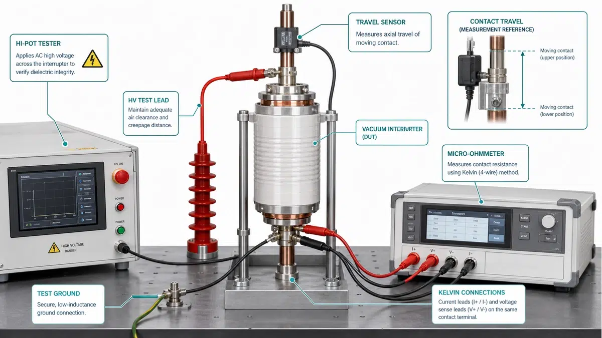
Un VCB intérieur de 12 kV a été mis hors service après qu'un événement de relais ait montré une extinction d'arc retardée sur une ligne d'alimentation. L'équipe de maintenance a mesuré les éléments suivants au cours d'un arrêt planifié.
| Poteau | Résultat de l'essai à haut débit | Résistance de contact | Mesure de l'essuyage | Diagnostic |
|---|---|---|---|---|
| A | Passe | 32 micro-ohms | 2,4 mm | En état de marche |
| B | Échec, les fuites augmentent avant le temps de maintien | 96 micro-ohms | 1,5 mm | Perte de vide et érosion de contact |
| C | Passe | 35 micro-ohms | 2,3 mm | En état de marche |
Les données mesurées permettent d'éviter une décision de réparation erronée. Le pôle B n'est pas seulement usé, il échoue également au test d'intégrité du vide, de sorte que le nettoyage de la face de contact ou le réglage de la course ne rétablira pas la fiabilité de l'interruption. L'action corrective consiste à remplacer l'interrupteur du pôle B ou l'ensemble tripolaire complet si l'équipementier n'autorise pas le remplacement d'un seul pôle assorti. Les pôles A et C ne peuvent rester en service qu'une fois que leurs rapports d'essai ont été ajoutés au dossier de maintenance et que l'intervalle d'inspection suivant a été raccourci.
Cet exemple montre également pourquoi la résistance de contact seule ne suffit pas. Si le pôle B avait montré une résistance de 96 micro-ohms mais avait passé les contrôles du pot d'échappement et de la course, la première mesure corrective aurait consisté à inspecter le joint, à le nettoyer et à le tester à nouveau. Comme le pot d'échappement n'a pas fonctionné, la décision passe directement au remplacement.
Le remplacement est obligatoire en cas de défaillance de l'intégrité du vide, lorsque le déplacement ou l'essuyage atteint la limite d'usure de l'équipementier, ou lorsque le nombre d'opérations de défaut dépasse l'allocation de service déclarée. La remise à neuf n'est raisonnable que si le cadre, le mécanisme, le circuit secondaire et les interfaces des pôles restent conformes aux spécifications.
| Point de décision | Remplacer l'interrupteur ou le pôle | Remplacer la VCB complète |
|---|---|---|
| Un pôle ne passe pas le test du vide | Possible si l'équipementier autorise l'échange de pôles appariés | Requis si l'échange de pôles n'est pas pris en charge |
| Plusieurs pôles proches de la limite d'usure | Remplace généralement le jeu de perches | Envisager une VCB complète si le mécanisme est également usé |
| Mécanisme de déplacement instable | Mécanisme de service d'abord | Remplacer si les pièces sont obsolètes ou si le cadre est endommagé |
| Âge et dossiers | Acceptable si les dossiers sont complets | Préférer le remplacement en cas d'absence d'enregistrements et d'âge élevé |
| Disponibilité des pièces de rechange | Interrupteur disponible avec rapport d'essai | Disjoncteur complet nécessaire si l'interrupteur est obsolète |
Pour le choix du produit, comparez le résultat du diagnostic avec la liste de contrôle de l Disjoncteur à vide XBRELE page. Pour la documentation relative à l'acceptation, utilisez l'option Liste de contrôle pour l'acceptation du TFA/TSA par le VCB.
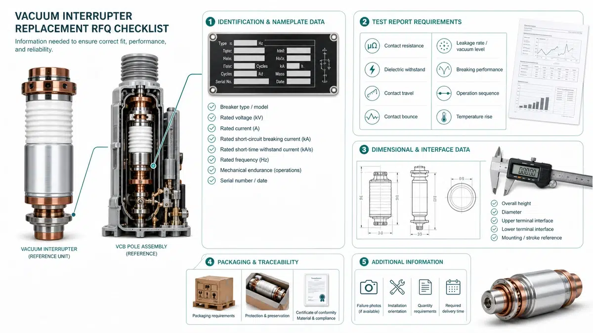
Avant de lancer un appel d'offres, rassemblez la plaque signalétique, le schéma de câblage, les dimensions des pôles, le type de mécanisme de fonctionnement, la tension de commande, le courant nominal, le courant de rupture en cas de court-circuit et le dernier rapport d'essai. Un fournisseur ne peut pas confirmer l'interchangeabilité à partir de la seule classe de tension.
| Point de l'appel d'offres | Pourquoi est-ce important ? |
|---|---|
| Tension nominale, BIL et fréquence | Confirme la classe diélectrique |
| Courant nominal et courant de rupture | Confirme la fonction thermique et de défaut |
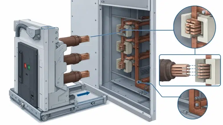
| Dimensions des contacts et des pôles | Confirme l'ajustement mécanique |
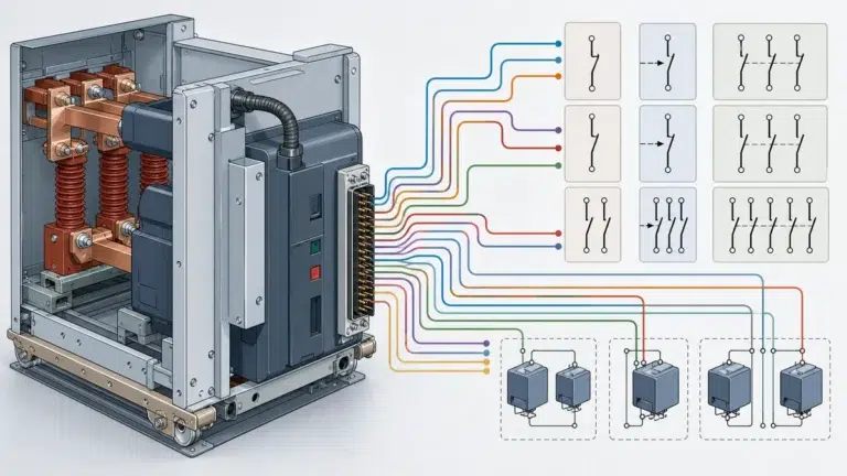
| Tension de commande et schéma des contacts auxiliaires | Empêche la désynchronisation du circuit secondaire |
| Enregistrements Hi-pot, micro-ohm et timing | Indique le mode de défaillance actuel |
| Rapport d'essai et méthode d'emballage requis | Protège la qualité pendant la livraison |
Pour la préparation des devis, utilisez le Liste de contrôle VCB RFQ. Pour le contexte de la méthode d'essai de résistance, voir le guide de test de la résistance de contact micro-ohm. Pour le contexte des normes, utilisez la fonction Page de la norme IEEE C37.09 puis vérifier les limites finales par rapport au manuel de l'équipementier.
Effectuez d'abord le test d'intégrité du vide, puis vérifiez la résistance des contacts et la course. L'échec de l'essai au pot d'échappement indique une perte de vide. Un résultat positif avec une résistance croissante et une réduction de l'essuyage indique une érosion du contact ou des problèmes de force de contact.
Non. Un interrupteur à vide dont la perte de vide est confirmée n'est pas réparable sur le terrain. Remplacer l'interrupteur ou l'assemblage de pôles conformément à la conception de l'équipementier.
Non. Une résistance de contact élevée peut également provenir de bornes desserrées, de joints contaminés, d'une faible force de contact ou d'une erreur de mesure. Confirmez la connexion d'essai, comparez les trois pôles et vérifiez la course avant de décider du remplacement.
Utiliser l'intervalle de maintenance OEM comme source principale. Raccourcir l'intervalle en cas d'interruption pour cause de défaut, de service de commutation élevé, de contamination côtière ou d'absence de dossiers d'entretien.
Uniquement si la conception de l'équipementier permet le remplacement d'un seul pôle et si le nouveau pôle correspond au cadre, à la course, aux dimensions de l'interface et aux exigences d'essai de l'équipement existant. Dans le cas contraire, remplacer le jeu de pôles ou le disjoncteur complet.
L'enregistrement le plus solide combine le résultat de l'essai à chaud, la résistance de contact, la course/le balayage, le chronométrage, le nombre d'opérations et l'inspection visuelle. Un chiffre isolé est plus faible qu'une chaîne de preuves cohérente.
L'âge seul n'est pas toujours un déclencheur de remplacement, mais il augmente la priorité d'inspection. Si le disjoncteur passe avec succès les tests de vide, de résistance, de course et de synchronisation, il ne faut continuer à l'entretenir qu'avec un intervalle d'inspection documenté et une stratégie de rechange.