முழு விவரக்குறிப்புகள் வேண்டுமா?
அனைத்து சுவிட்ச்கியர் பாகங்களின் விரிவான வரைபடங்கள் மற்றும் தொழில்நுட்ப அளவுருக்களுக்கு, எங்கள் 2025 தயாரிப்புப் பட்டியலைப் பதிவிறக்கவும்.
பட்டியல் பெறுக
அனைத்து சுவிட்ச்கியர் பாகங்களின் விரிவான வரைபடங்கள் மற்றும் தொழில்நுட்ப அளவுருக்களுக்கு, எங்கள் 2025 தயாரிப்புப் பட்டியலைப் பதிவிறக்கவும்.
பட்டியல் பெறுக அனைத்து சுவிட்ச்கியர் பாகங்களின் விரிவான வரைபடங்கள் மற்றும் தொழில்நுட்ப அளவுருக்களுக்கு, எங்கள் 2025 தயாரிப்புப் பட்டியலைப் பதிவிறக்கவும்.
பட்டியல் பெறுக
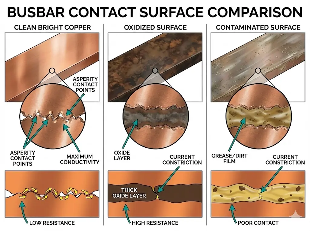
Understand busbar joint heating, verify the correct surface and hardware specification, and plan torque and thermal checks using the installed equipment's instructions.
கடைசியாகப் புதுப்பிக்கப்பட்டது: .
A reliable busbar bolted joint depends on the complete connection design: contact surfaces, hardware, alignment, assembly torque and operating conditions. A generic bolt-size torque table cannot establish the correct clamping force for every switchgear assembly.
This guide explains the checks to make during installation and maintenance, including the relationship between contact resistance and heating. Use the equipment manufacturer’s drawings and instructions for the actual cleaning method, joint compound, fasteners, torque and maintenance requirements.
Work conditions: cleaning, tightening, dismantling and contact-resistance testing are de-energized maintenance activities. Qualified personnel must isolate all sources, address backfeed, verify absence of voltage and apply the required grounding and lockout procedures. Energized thermography is a separate inspection activity governed by the site’s electrical-safety procedure.
The joint’s resistive loss is P = I²R, where current is in amperes, resistance in ohms and power in watts. At constant current, increasing resistance by 50% increases heating power by 50%, to 1.5 times the original value. A 2.25-times result instead follows from increasing current by 50% while keeping resistance constant.
| Illustrative resistance | Loss at 1,600 A |
|---|---|
| 10 μΩ | 25.6 W |
| 15 μΩ | 38.4 W |
| 20 μΩ | 51.2 W |
| 50 μΩ | 128 W |
These are arithmetic examples, not acceptance bands for a particular joint. Loss alone does not determine temperature: heat conduction into the bars, enclosure ventilation, ambient conditions, geometry and load duration also matter. A measured resistance or thermogram must therefore be interpreted against the equipment design and a suitable baseline.
Contamination, damaged contact surfaces, incorrect hardware or loss of clamping force can increase resistance. Thermal cycling and mechanical movement may contribute to deterioration, but a warm joint is not proof that its bolts simply need more torque.
First identify bare copper, plated copper, aluminium or a specified transition interface. The cleaning method appropriate for one finish may damage another. For example, Schneider’s MotorSeT installation instructions require clean contact faces and supplied hardware, and prohibit abrasive cleaning of plated surfaces. The torque table is specific to that equipment.
Confirm that the bars, holes and supports align without forcing the connection into place. Check damage and dimensional deviations against the manufacturer’s drawing. Do not machine a plated contact face or introduce a generic flatness tolerance without approval. Schneider’s Masterclad installation instructions specifically caution against bending or forcing bars to make a connection.
Verify bolt material, strength class, diameter, length, nuts, washers and any required coatings against the bill of materials. A higher bolt strength class or a stainless-steel substitution is not automatically compatible with the designed joint. Replace damaged hardware using the manufacturer’s requirements.
Use the specified washer type, quantity, orientation and location. Flat, spring and other locking washers have different functions; they are not interchangeable simply because they fit the bolt. Do not add washers or change the stack to compensate for a damaged or misaligned bar.
Confirm whether the actual contact interface requires a compound, its approved product and where it is applied. Separately confirm the required thread condition. Adding lubricant or anti-seize can change the relationship between applied torque and bolt preload. Do not reduce a copper torque value by a fixed percentage to create an aluminium or stainless-steel specification.
| சரிபார்க்கவும் | Record |
|---|---|
| Connection identity | Equipment model, joint location and drawing revision |
| Hardware and surfaces | Fastener specification, washer stack, contact finish and approved compound |
| Assembly requirement | Manufacturer’s torque, units, thread condition and tightening sequence |
| Tool and completion | Suitable torque tool, calibration status, applied setting and installer record |
If the instructions are missing or conflicting, obtain the correct connection specification before completing the joint. A torque for an enclosure fastener or a different bus connection must not be reused by assumption.
Do not impose a universal 30%/70%/100% tightening sequence or use an impact tool for final torque unless the equipment procedure specifically allows it. Torque is an assembly control; a later wrench reading alone is not a direct measurement of remaining clamping force.
Manufacturer requirements differ. Schneider’s FlexSeT instructions specify that its busbar joints must not be retightened after the pre-energizing checkout. Its MCC maintenance guidance also distinguishes loose or overheated joints from joints that do not need retightening. These are equipment-specific examples, not instructions for every MV assembly.
Use the manual, service environment, operating history and site maintenance plan to determine inspection intervals and permitted corrective work. Do not apply a blanket 48–72-hour or 30-day re-torque schedule. Any permitted tightening takes place after safe isolation, never while the busbar is energized.
Thermography under representative load can help identify abnormal heating. Record load current, ambient conditions, viewing position, camera settings and the joint identity. Compare similar connections under comparable conditions and with earlier records. A low-load scan may not reveal an issue that becomes apparent at higher load.
Shiny copper and aluminium reflect infrared radiation and can produce misleading apparent temperatures. Fluke’s reflectivity guidance explains this measurement limitation. Do not touch energized conductors to improve a thermal target. Plan any approved target preparation during an outage, and use approved inspection access and safety controls.
A localized anomaly can justify investigation, but overload, phase imbalance, connection condition and measurement error can produce different or overlapping patterns. Fluke’s electrical troubleshooting guidance calls for follow-up measurements to establish the cause. Apply the equipment limits and site response criteria; no single temperature difference in this article is a universal pass/fail or shutdown threshold.
Look for damage to bars, hardware, insulation, barriers and supports, together with contamination and signs of overheating or movement. Distinguish harmless finish changes from damage using the equipment guidance. For example, SureSeT MV maintenance instructions distinguish slight silver-plating tarnish from severe discoloration that requires investigation.
Follow the approved disposition for a suspect joint: inspection, repair, replacement or permitted reassembly. Do not assume that turning every bolt cures overheating. Retain photographs, the reported symptoms, parts replaced and the relevant torque record. Restore insulation and covers before completing the return-to-service checks.
When specified, use an appropriate four-wire low-resistance measurement procedure with the equipment safely isolated. Define the measurement endpoints, test current, temperature and any parallel paths that could affect the reading. Compare with the manufacturer’s criteria or a valid baseline taken under comparable conditions. There is no universal micro-ohm pass/fail band for joints of different lengths, materials and geometries. Our contact-resistance testing guide provides related context; the equipment procedure governs the test.
For high-current designs, obtain the verified bar arrangement, overlap, hole pattern, hardware and support details from the equipment supplier. Do not create these dimensions from a universal bolt count, spacing or overlap-to-thickness ratio. Temperature-rise and short-circuit duties apply to the assembled arrangement, including connections to the வெற்றிட மின்சுற்று முறிப்பி and other apparatus.
Q1: Can I use an impact wrench for the final connection torque?
Use the tool and method required by the equipment manufacturer. Do not treat an impact-tool setting as a substitute for a specified torque-control procedure.
Q2: Can surface colour tell me the joint resistance?
No. Finish, oxidation, contamination and temperature history differ. Inspect under the manufacturer’s guidance and use a defined resistance test when required.
Q3: What torque applies to stainless-steel bolts in aluminium busbars?
The approved assembly specification must address the actual fasteners, thread condition, washers and bars. Do not derive it by subtracting a generic percentage from another torque value.
Q4: How often should joints be thermally inspected?
Set the interval through the equipment maintenance instructions and the site’s condition-based or scheduled programme. Record the load and measurement conditions so repeat scans can be compared.
Q5: Will re-torquing repair a hot joint?
Only if the approved diagnosis and repair procedure establish that it is appropriate. Damage, contamination, overload or a measurement error may require a different response.
Q6: Are joint compound and thread anti-seize interchangeable?
No. Confirm the approved material and its application location separately for contact surfaces and threads. Changing thread lubrication can change preload at the same torque.
Q7: How should copper-to-aluminium connections be assembled?
Use the equipment manufacturer’s approved transition design, hardware, surface preparation and compound requirements. Do not substitute a generic washer arrangement for an engineered transition.