पूरी विशिष्टताएँ चाहिए?
सभी स्विचगियर घटकों के विस्तृत आरेखों और तकनीकी मापदंडों के लिए हमारा 2025 उत्पाद कैटलॉग डाउनलोड करें।.
कैटलॉग प्राप्त करें
सभी स्विचगियर घटकों के विस्तृत आरेखों और तकनीकी मापदंडों के लिए हमारा 2025 उत्पाद कैटलॉग डाउनलोड करें।.
कैटलॉग प्राप्त करें सभी स्विचगियर घटकों के विस्तृत आरेखों और तकनीकी मापदंडों के लिए हमारा 2025 उत्पाद कैटलॉग डाउनलोड करें।.
कैटलॉग प्राप्त करें
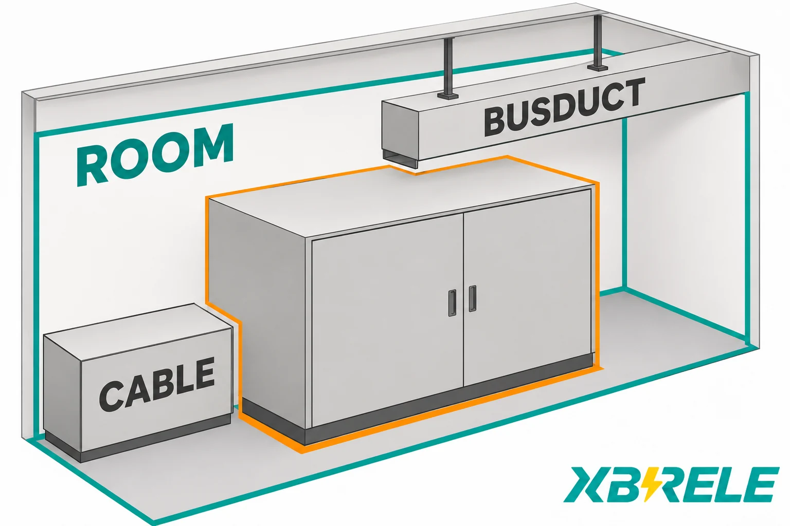
Review transformer GA drawings for cable entry, terminal geometry, busduct flanges, support loads, access and installation dimensions before design freeze.
A transformer general arrangement (GA) drawing usually clears the room check long before anyone discovers that the connection does not close. The enclosure fits between the walls, the door swings, the plinth is poured — and then the cable box turns out to be too shallow for the bend radius of the incoming cable, or the busduct flange arrives with a hole pattern that matches nothing on the terminal cover. None of those failures is visible in an overall dimension chain. They live at the interfaces, and interfaces are exactly what a GA package is supposed to freeze.
This review is therefore framed around three separate questions rather than one: does the outline fit the room, does the connection fit the equipment it must land on, and does the installed unit remain serviceable and replaceable. Procurement and project engineers can answer all three from a properly bound drawing package, provided the package is read as an interface map and not as a single outline elevation.
An overall-fit check compares the transformer’s length, width and height against the available room volume. It is necessary and it is the easiest thing on the drawing to verify, which is why reviews tend to stop there. The problem is that outline fit and connection fit are independent facts. A unit can satisfy every room dimension while its cable box faces a wall, its busduct flange lands 200 mm off the switchboard centreline, or its front panels cannot be removed because the maintenance aisle was measured to the enclosure face rather than to the panel swing.
Three distinct questions need three distinct answers:
Before any of that can be judged, the document itself has to be identified. A GA drawing is only usable evidence when it is bound to a specific configuration: drawing number, revision, and status — preliminary, issued for approval, approved for manufacture, or as-built. A drawing marked “preliminary” carries no manufacturing weight regardless of how complete it looks, and an as-built record describes what was delivered rather than what was approved. Mixing these three statuses in one review is the most common source of false confidence, because the room may have been cleared against a preliminary outline while the equipment was built to a later revision with a deeper cable box.
Bind the same identity to the equipment the drawing describes: model designation, rated power and voltage class, cooling arrangement, enclosure type and ingress protection, and every accessory that changes the external envelope — cable boxes, fans, temperature sensors, thermostats, lifting lugs, jacking pads. An accessory omitted from the drawing is an accessory omitted from every clearance check made from it.
The distinctions worth fixing in a review file are:
| Evidence type | What it establishes | What it cannot establish |
|---|---|---|
| Outline GA | Room fit, overall envelope, weights, installed position | Detailed terminal geometry, hole patterns and hardware unless explicitly included |
| Detailed connection drawing | Terminal pads, flange interfaces, cable entry positions, phase arrangement | Anything outside the drawn interface |
| As-built record | What was actually supplied and installed | That the design intent was correct |
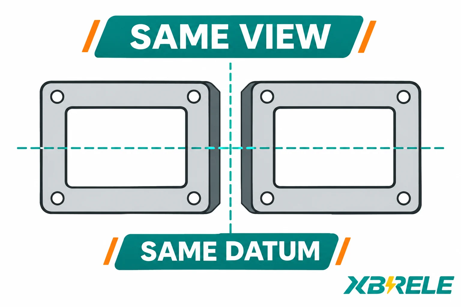
Two documents can each carry a correct dimension and still describe a misalignment, because the dimensions were taken from different origins. The fix is procedural and cheap: fix the datums before comparing anything.
A workable convention states, explicitly and on the drawing itself:
No universal clearance figure can be handed out here, and any drawing set that implies one should be treated with suspicion. Clearances follow the applicable design rules for the voltage class, the enclosure, the earthing arrangement and the local code, and they are stated on the approved drawing for the specific unit.
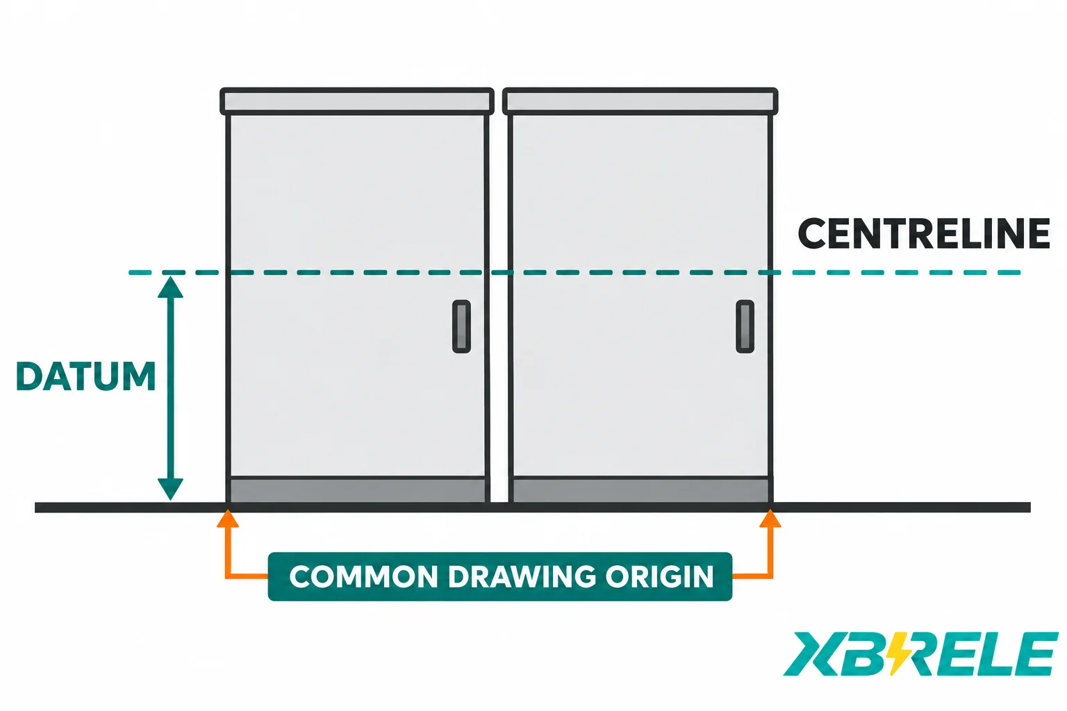
The mechanism behind most “two correct dimensions” failures is simple: one number is measured to the top of the structural slab and the other to finished floor, or one is taken from the transformer centreline and the other from the room wall. Both are internally correct. Together they describe a flange that does not meet its mating flange. A shared baseline and a shared terminal centreline, drawn once and referenced everywhere, remove the ambiguity before fabrication starts.
A cable box is easy to review as an outside shape and hard to review as a working volume. Outer dimensions tell you whether it clears the wall. They tell you nothing about whether the cable can be terminated inside it.
The inputs to this check come from the cable, not from the transformer. For each incoming and outgoing circuit, collect the cable count, cable type and insulation, conductor material and cross-section, screen and armour construction, and the termination method actually specified — compression lug, mechanical connector, or a busbar connection. From the cable manufacturer’s data, take the minimum bending radius for that construction under installation and under static service conditions, and the cable’s mass per metre. Then check the box against those numbers rather than against a rule of thumb.
Inside the box, the review has to confirm:
Terminal drilling, enclosure clearance and cable support are sometimes collapsed into a single “clearance” note on a GA. They are not the same thing: the terminal drilling is a machining fact, the enclosure clearance is a spatial fact, and the cable support is a structural fact. A historical connections guide for cast-resin distribution transformers — Schneider Electric’s Trihal connections guide NRJED311120EN, dated September 2011 — separates termination drilling, enclosure clearance and cable support in exactly this way, and states the governing principle plainly: the contractor must ensure that cables and busbars are adequately supported so that mechanical stresses are not imposed on the transformer terminals, busbars or bushings. That sentence is a design instruction, not a site preference. Cable and busbar weight, plus the dynamic load of a short circuit acting on a heavy conductor, must be addressed by the designed support system. Use building supports or manufacturer-approved structural supports and keep forces on terminals and bushings within their declared limits.
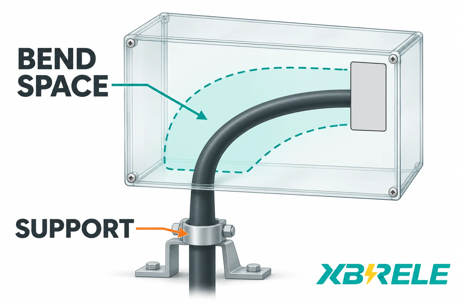
A useful test before design freeze: ask where the cable’s weight leaves the transformer. If the answer is “at the lug”, the support is missing, and no amount of additional box volume fixes it.
Busduct connections fail in a specific and predictable way: each party draws its own half of the interface correctly, and the two halves are never compared on the same sheet. Closing the interface means agreeing on a single coordinated detail that both the transformer supplier and the busduct supplier sign off.
The content of that detail:
द Canalis KR transformer/switchboard connection unit guide from Schneider Electric is useful here precisely because it treats the connection as a purchased, configured item rather than a generic junction: end feed units connect the lines mechanically and electrically, and the flange connection uses connection boxes, adapter flanges and seals or bellows as the project requires. The same guide’s pre-ordering note asks for the terminal elements, flanges and covers to be calculated before ordering. That is the coordination principle in one sentence — the interface parts are project-specific, and they must be resolved while the order is still open, not after the equipment arrives.
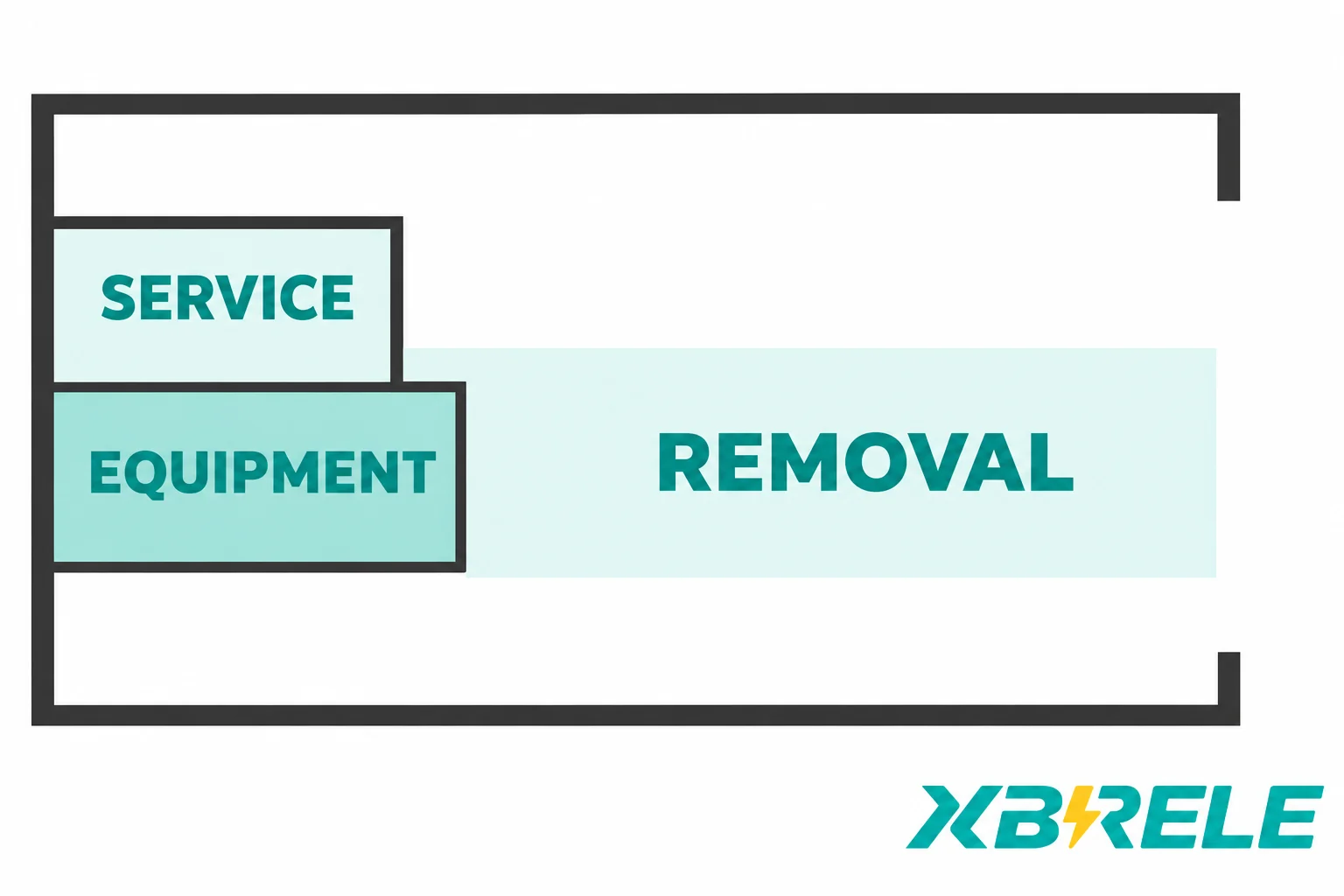
The installed footprint is the smallest of the envelopes that matter. Three others are larger and are usually discovered late.
Entry and replacement route. The unit has to reach its plinth, and one day it has to leave. Door widths, corridor turns, lift capacity, roof hatches and any temporary opening in the building envelope all constrain the transport envelope, which includes packaging and skids. A route that works for a palletised delivery may not work for a unit with cable boxes fitted on site, and a replacement route that requires removing a wall should be identified during review rather than during a failure.
Foundation, anchors and weight. Installed weight, plinth or foundation detail, anchor positions and anchor type, and the reactions the structure must accept. Where the transformer sits on a raised floor or a steel platform, review the support’s dynamic behaviour against the relevant excitation frequencies. Flexibility may isolate or amplify vibration depending on stiffness, damping and frequency; a structural assessment resolves the case.
Removable panels and maintenance access. HV and LV cable box covers, front panels, fan assemblies and temperature sensors all need removal space in front of them, and the space must be measured from the panel face, not from the enclosure. Fan replacement and sensor access frequently get forgotten because they sit at the top or rear of the unit.
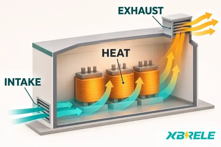
Ventilation air path. Dry-type transformers are air-cooled, and the enclosure and room must preserve the manufacturer’s required cooling path and avoid harmful hot-air recirculation. Low intake and high exhaust commonly assist natural convection, while forced-air arrangements need their own airflow assessment. A room that satisfies the dimensional clearance while blocking the inlet is thermally inadequate regardless of the drawing’s geometry. Ventilation and enclosure guidance belongs in the same review as the GA, because the air path is part of the installed envelope.
Live-part clearances. Taken from the applicable design rules for the specific voltage, enclosure and earthing arrangement, and stated on the approved drawing. No generic number is offered here, and none should be inferred from an unrelated project.
Lifting. Lifting is a separate document. Jacking pads, lifting lugs, the centre of gravity and any transport bracing belong on a dedicated lifting drawing, and the lift itself belongs to a qualified rigging plan prepared for the actual site conditions. The GA review confirms that the provisions exist and are consistent with the unit’s mass and shape; it does not substitute for the rigging plan.
The review only produces a result if it produces a record. A short interface register, maintained from issue for approval through to approved for manufacture, does more to prevent field rework than any single drawing check.
| Interface item | Drawing and datum | मालिक | Required confirmation | स्थिति |
|---|---|---|---|---|
| Terminal pad height above finished floor | Transformer GA, elevation, FFL datum | Transformer supplier | Confirmed against busduct layout and cable sweep | Open / Confirmed |
| Busduct flange hole pattern and phase mapping | Coordinated interface detail, stated view direction | Transformer and busduct suppliers jointly | Both parties sign the same detail sheet | Open / Confirmed |
| Cable box internal volume and gland plate position | Cable box detail | Transformer supplier | Checked against cable bending radius and termination method | Open / Confirmed |
| Foundation and anchor positions | Civil/foundation drawing, FFL datum | Project engineer | Reconciled with GA anchor layout | Open / Confirmed |
| Installed and transport weights | GA and lifting drawing | Transformer supplier | Passed to structural and logistics parties | Open / Confirmed |
| Enclosure type and ingress protection | GA and datasheet | Transformer supplier | Matches room environment and washdown/ventilation strategy | Open / Confirmed |
| Service and removal envelopes | GA plan view | Project engineer | Checked against room, doors and future replacement route | Open / Confirmed |
| Superseded revision register | Document control | Project engineer | Every superseded sheet withdrawn from site and fabrication | Open / Confirmed |
A conditional case shows why the register earns its place. Consider an indoor project with a cast-resin transformer feeding a switchboard through a top-entry busduct, with the foundation detail issued early because the civil works were on the critical path. The terminal pad height on the preliminary GA was used to set the plinth and the embedded anchor positions. At the approval stage, the transformer supplier revises the terminal height after the cable box configuration changes to accommodate larger incoming cables. Every individual drawing is now correct: the plinth matches the preliminary GA it was based on, and the final GA matches the equipment that will be built. The busduct, however, arrives with its flange at the old plane, the flexible section is at the limit of its travel, and the installation crew discovers the mismatch on site.
The wrong resolution is to slot the flange holes or drill a new pattern in the field. That changes a calculated interface, removes protective plating, distributes metal swarf near live parts, and leaves no record of what the joint now is. The right resolution is a coordinated revision: the transformer supplier reissues the GA with the changed terminal height, the busduct supplier reissues the layout with the matching flange plane, the foundation detail is reissued if the anchor positions actually move, and all three are re-approved before either item is released to manufacture. The register records the change, the date, and who confirmed what.
The document set that makes this work is modest:
For the equipment side of that package, the cast-resin dry-type range is described on the XBRELE dry-type transformer page. Catalogue positioning is a starting point, not a specification: no-load and load losses, the cooling rating that applies to the actual duty, enclosure type, ingress protection and the GA itself should be requested as project-specific agreed data rather than extracted from a general table. The practical route is to send the room constraints, cable schedule and busduct interface along with the required rating and duty, and ask for a GA and a connection detail against them — the contact page is the place to submit that brief.
A GA drawing places the whole unit in its space: overall dimensions, installed position, weights, cable box and accessory envelopes, and the clearances the room must provide. A connection drawing zooms into a specific interface and defines the geometry needed to make a joint — terminal pad material and drilling, flange dimensions and hole pattern, phase arrangement, entry positions. The GA tells you the equipment fits the room; the connection drawing tells you the cable or busduct fits the equipment. A package containing only an outline leaves detailed interfaces undefined unless the required detail is explicitly incorporated, and a package with only connection drawings hides the room-level conflicts that stop the unit being installed at all.
Do not use the terminals or bushings as an unengineered support for the busduct run. The coordinated support design must carry the specified weight, movement and fault loads while keeping connection forces within the manufacturer’s limits. Approved structural supports may be incorporated in the transformer or connection assembly. A flexible connector or bellows accommodates only its specified movement and load; it is not a general cure for misalignment or missing supports. Identify each support and its responsible supplier on the agreed interface detail.
Electrical phase sequence is a time relationship and does not change when someone views the equipment from the opposite end. What changes is the apparent left-to-right terminal order. A drawing that says only “A-B-C from the left” can therefore be misread. State the viewing direction, terminal identities and any transposition, then map corresponding phases on one coordinated detail. This remains useful for both symmetrical and non-symmetrical layouts; visual symmetry does not prove electrical identity.
They do not. Catalogue dimensions describe a family or a representative configuration, not the specific unit on order, and they generally omit the things that decide the interface: the exact terminal pad height for the selected cable box, the flange hole pattern for the chosen busduct adapter, the accessory envelope for the fans and sensors actually specified. Catalogue data is appropriate for early space planning and for framing the enquiry. Once the design is being frozen, the approved GA for the ordered configuration is the controlling document, and it should carry a revision and a status that make clear it has been approved for manufacture rather than merely issued for comment.