पूरी विशिष्टताएँ चाहिए?
सभी स्विचगियर घटकों के विस्तृत आरेखों और तकनीकी मापदंडों के लिए हमारा 2025 उत्पाद कैटलॉग डाउनलोड करें।.
कैटलॉग प्राप्त करें
सभी स्विचगियर घटकों के विस्तृत आरेखों और तकनीकी मापदंडों के लिए हमारा 2025 उत्पाद कैटलॉग डाउनलोड करें।.
कैटलॉग प्राप्त करें सभी स्विचगियर घटकों के विस्तृत आरेखों और तकनीकी मापदंडों के लिए हमारा 2025 उत्पाद कैटलॉग डाउनलोड करें।.
कैटलॉग प्राप्त करें
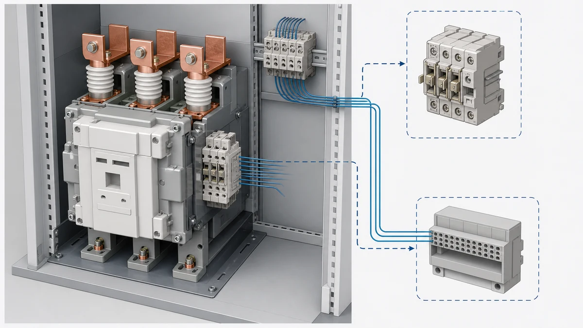
Vacuum contactor auxiliary contact wetting current is a small but important detail in control-circuit reliability. A vacuum contactor may switch the power circuit correctly while its auxiliary feedback circuit becomes unreliable because the current through the auxiliary contact is too low for the contact class, the PLC input does not draw enough current, or the input module architecture creates an unexpected return path.
The result is usually not dramatic at first. A PLC input may flicker, fail to change state, show a delayed transition, or pass factory testing but become intermittent after storage or light-duty operation. The root cause is often a mismatch between the auxiliary contact's documented minimum-current requirement and the real current supplied by the PLC or input interface.
Auxiliary contacts are often treated as simple open-or-closed devices, but their electrical behavior depends on the contact material, rating class, voltage, current, contamination, and time in service. In low-energy PLC feedback circuits, the current may be far below the level used in traditional relay circuits.
ABB's ConVac auxiliary-contact documentation warns that insufficient current can increase oxidation resistance and identifies a minimum-current requirement for a specified auxiliary-contact class. The important engineering point is not to copy a value from memory or from a different product family. The applicable auxiliary-contact class and its ratings must come from the exact vacuum contactor documentation being used. The ABB ConVac vacuum contactor manual is the primary source for the product-specific requirement stated here.
When the current is too low, the contact may close mechanically but still present enough resistance to prevent the PLC input from seeing a valid closed state. In other cases, the input may work during a clean bench test but fail after the contact surface oxidizes, after the equipment sits idle, or after many low-energy operations.
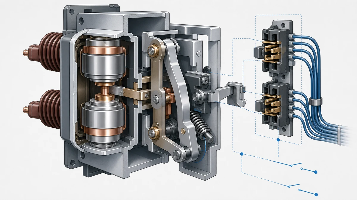
The most common failure pattern is a feedback loop built from individually acceptable parts that were never checked as a complete circuit. A vacuum contactor auxiliary contact may be rated correctly for its intended class, and a PLC input module may be rated correctly for its input type, but the combination may still not provide enough wetting current.
The risk is higher when the feedback circuit uses an internally supplied digital input, a low-current electronic input, long cable runs, interposing terminals, multiple series contacts, or input cards with diagnostic electronics. Each element can affect the current available through the auxiliary contact or the voltage finally seen by the PLC input. Use the NO/NC auxiliary-contact scheme guide to review terminal assignment, state logic, and common wiring mistakes.
A practical review should answer three questions before commissioning:
This is especially important for vacuum contactor status signals used in permissives, sequence proving, trip logic, remote indication, and interlocking. A false "open" or false "closed" indication may cause nuisance alarms, failed starts, or unsafe assumptions in the control logic.
A PLC input is not just a label such as "24 VDC input." The internal design determines the current drawn, the voltage threshold, the leakage tolerance, and the acceptable closed-contact voltage loss.
ABB's Novolink documentation gives an example of a digital input with an internal supply, a nominal input current, and a maximum permitted closed-contact voltage loss. That example reinforces a broader rule: PLC/input-interface acceptance must be checked from the actual input module documentation, not inferred from a generic PLC description.
If the input provides only a small sensing current, the vacuum contactor auxiliary contact may not receive enough wetting current for the specified auxiliary-contact class. If the contact, cable, or terminal path introduces too much voltage loss, the input may not recognize the closed contact reliably. Both conditions can appear as intermittent indication even when the contactor itself is operating normally.
Rockwell's documentation for an auxiliary dry-contact input also points in the same direction: the supplied current and voltage are defined by the associated 100-E/104-E equipment and IEC 60947-1. In practice, this means both ends of the feedback circuit must be matched. The contact side and the input side cannot be evaluated independently.
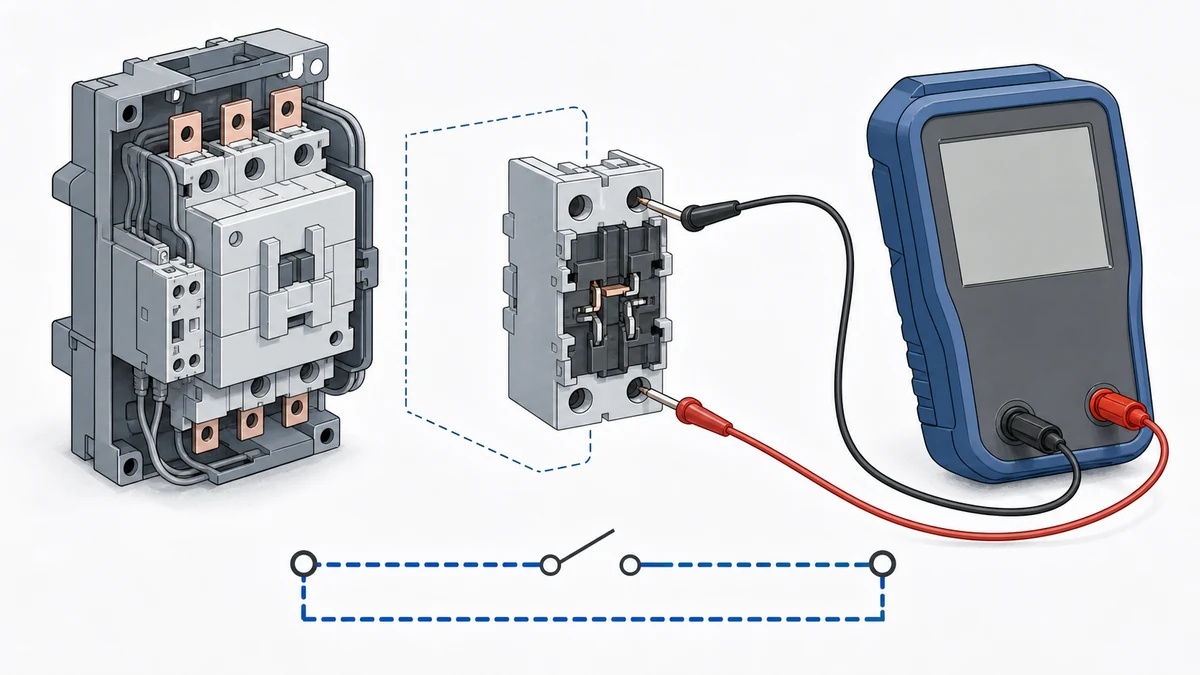
Commissioning should prove the complete auxiliary-feedback circuit under real wiring conditions. A drawing review is necessary, but it is not enough if the final installation includes long runs, shared commons, paralleled inputs, terminal blocks, auxiliary relays, pilot lights, surge suppression, or module-specific diagnostics. Reference the MV contactor wiring examples for coils, auxiliary contacts, and permissive logic patterns.
A useful commissioning check includes:
Schneider notes that input-interface behavior can depend on the specific module design when inputs are paralleled. That warning matters in vacuum contactor panels because feedback signals are sometimes shared between a PLC, protection relay, remote terminal unit, lamp circuit, or maintenance test point. When inputs are paralleled, return paths and input architecture belong in commissioning checks, not just schematic assumptions.
The safest design approach is to avoid guessing any wetting-current value. Instead, build the feedback circuit around the exact documents for the vacuum contactor auxiliary contact and the exact documents for the PLC or input interface.
For new designs, specify the auxiliary contact and input module together. If the PLC input current is below the auxiliary contact's documented minimum-current requirement, use an approved interface method rather than hoping the circuit will remain clean. Depending on the project standard and manufacturer guidance, that may mean a suitable interposing relay, an input module with appropriate current characteristics, a different auxiliary-contact class, or a validated contact-monitoring interface. For controller isolation and signal interfacing, use the interposing relay control patterns.
For replacements, do not assume that a new vacuum contactor or a new PLC input card behaves like the old one. A contactor retrofit may change the auxiliary-contact block. A PLC modernization may reduce sensing current. A control-power change may alter input thresholds. Any of these changes can turn a previously reliable feedback loop into a marginal low-energy circuit.
The documentation trail should identify:
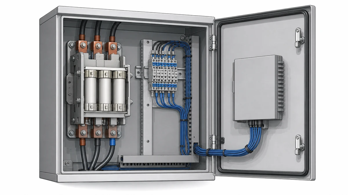
A wetting-current issue is often mistaken for a defective contactor, loose wire, bad PLC card, or software problem. Those causes are possible, but the investigation should include the auxiliary-contact current and input-module design when symptoms are intermittent or load-dependent.
Common symptoms include a PLC input that changes state only after several contactor operations, an input that reads correctly with a meter but not through the PLC, a feedback signal that works on one module type but not another, or a signal that becomes unreliable after a control-system upgrade. Another clue is that the contactor power function remains normal while only the status feedback is questionable.
A high-impedance digital meter can also mislead troubleshooting. It may show voltage present even when the input circuit cannot supply the current needed for reliable contact wetting or a valid input state. Commissioning should therefore rely on the module documentation and circuit behavior under actual load, not only open-circuit voltage readings.
The research evidence points to one consistent conclusion: reliable vacuum contactor feedback is a system property. ABB's ConVac material highlights the contact-side concern: insufficient current can increase oxidation resistance, and the correct minimum-current requirement depends on the exact auxiliary-contact class. ABB's Novolink material highlights the input-side concern: actual digital input characteristics, including current and closed-contact voltage loss, must be checked. Rockwell reinforces the need to match the auxiliary dry-contact input with the equipment that supplies its voltage and current. Schneider adds that paralleled inputs and module architecture can change behavior in the field. Use the XBRELE वैक्यूम कॉन्टैक्टर रेंज to match the control and switching duty to an available product family.
Together, these points support a disciplined rule for vacuum contactor auxiliary circuits: do not validate the contact alone, and do not validate the PLC input alone. Validate the installed loop.
Vacuum contactor auxiliary contact wetting current is the current that flows through the auxiliary contact when it is closed in a control or feedback circuit. In practical terms, it must be high enough for the specified auxiliary-contact class to maintain a reliable low-resistance closed state. ABB's ConVac documentation warns that insufficient current can increase oxidation resistance, so the correct value must be taken from the exact device documentation.
A generic label such as "digital input" or "24 VDC input" does not prove compatibility. The actual input module may have an internal supply, a defined nominal input current, input thresholds, leakage behavior, and a maximum allowed closed-contact voltage loss. ABB's Novolink documentation shows why the exact input-interface data matters. If the input current is too low or the voltage loss is too high, the PLC may not read the vacuum contactor auxiliary contact reliably.
The correct way is to match both ends of the feedback circuit. Confirm the vacuum contactor auxiliary-contact class and minimum-current requirement from the exact contactor documentation, then confirm the PLC or input-interface current, voltage, and closed-contact voltage-loss requirements from the exact module documentation. The installed wiring path should then be tested under real operating conditions.
When PLC inputs are paralleled, the return path and internal input architecture can affect how the circuit behaves. Schneider notes that behavior can depend on the specific module design. For vacuum contactor feedback, this means paralleled PLC, relay, lamp, or monitoring inputs should be checked as a complete circuit rather than assumed to share the signal harmlessly.
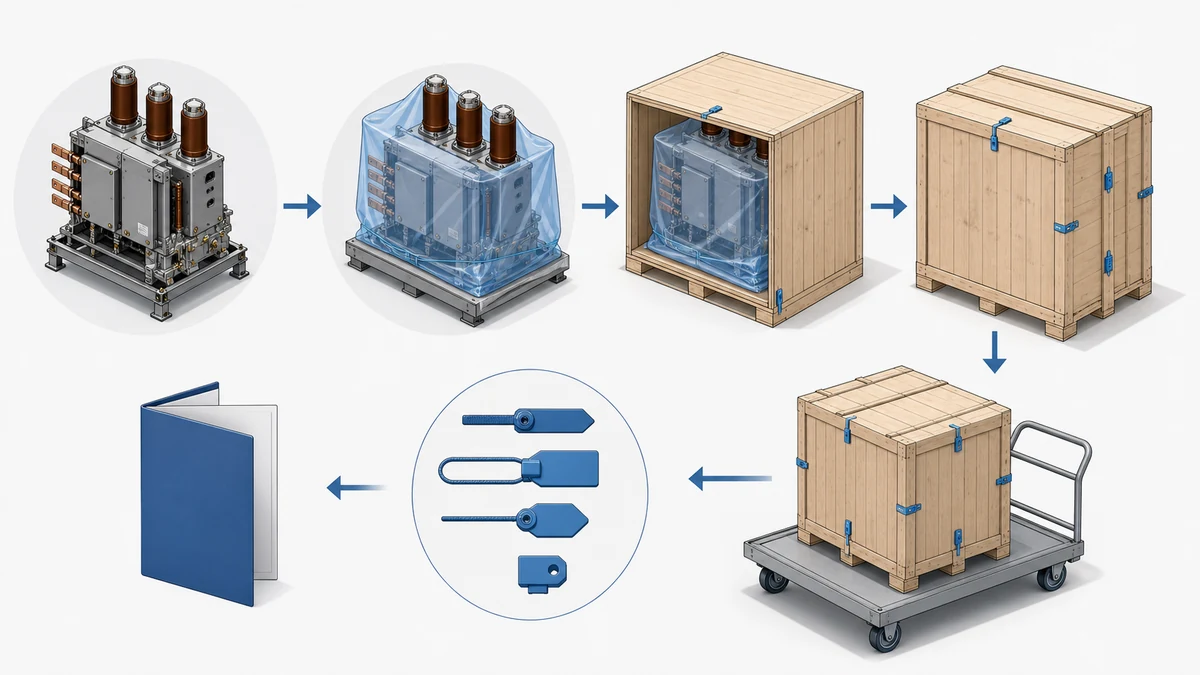
Documentation prevents a like-for-like assumption from becoming a reliability problem. A replacement vacuum contactor may use a different auxiliary-contact block, and a replacement PLC module may draw a different input current. The auxiliary-contact documentation and the input-module documentation should both be reviewed before accepting the modified feedback circuit.