Нужны полные технические характеристики?
Загрузите наш каталог продукции 2025 года, чтобы ознакомиться с подробными чертежами и техническими параметрами всех компонентов распределительного устройства.
Получить каталог
Загрузите наш каталог продукции 2025 года, чтобы ознакомиться с подробными чертежами и техническими параметрами всех компонентов распределительного устройства.
Получить каталог Загрузите наш каталог продукции 2025 года, чтобы ознакомиться с подробными чертежами и техническими параметрами всех компонентов распределительного устройства.
Получить каталог
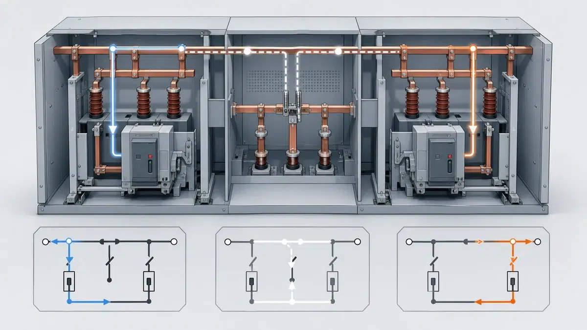
Надёжность схемы перевода шин с вакуумными выключателями (VCB) зависит от логики блокировок, обратной связи выключателей и подтверждённой последовательности операций. В распределительных системах среднего и низкого напряжения управление переводом может переключать нагрузку с нормального ввода на резервный через секционный выключатель либо восстанавливать питание от основного источника после подтверждения допустимых условий. Инженерная задача состоит не просто во включении следующего выключателя: нужно подтвердить наличие нужного источника, правильное состояние выключателей, физическую готовность VCB к работе и невозможность параллельного соединения источников, если такая схема специально не предусмотрена и не защищена.
Для области применения, ограниченной VCB, выражение «логика блокировок VCB в схеме перевода шин» означает совокупность логики управления, обратной связи, разрешений, блокировок и проверки, которая управляет командами отключения и включения VCB при переключении источника. В рекомендациях ABB по схемам перевода AKD10 указаны входы ПЛК (PLC), такие как напряжение источников, состояние вводного и секционного выключателей, положение выкатного выключателя и режим перевода, а также выходы вроде сигналов включения и отключения. В тех же рекомендациях описана блокировка вводного и секционного выключателей для предотвращения параллельного соединения источников. В рекомендациях Siemens по быстрому переводу шин также подчёркивается контроль напряжения основного ввода, шин электродвигателей и резервного источника, а также блокирование перевода при определённых ненормальных условиях.
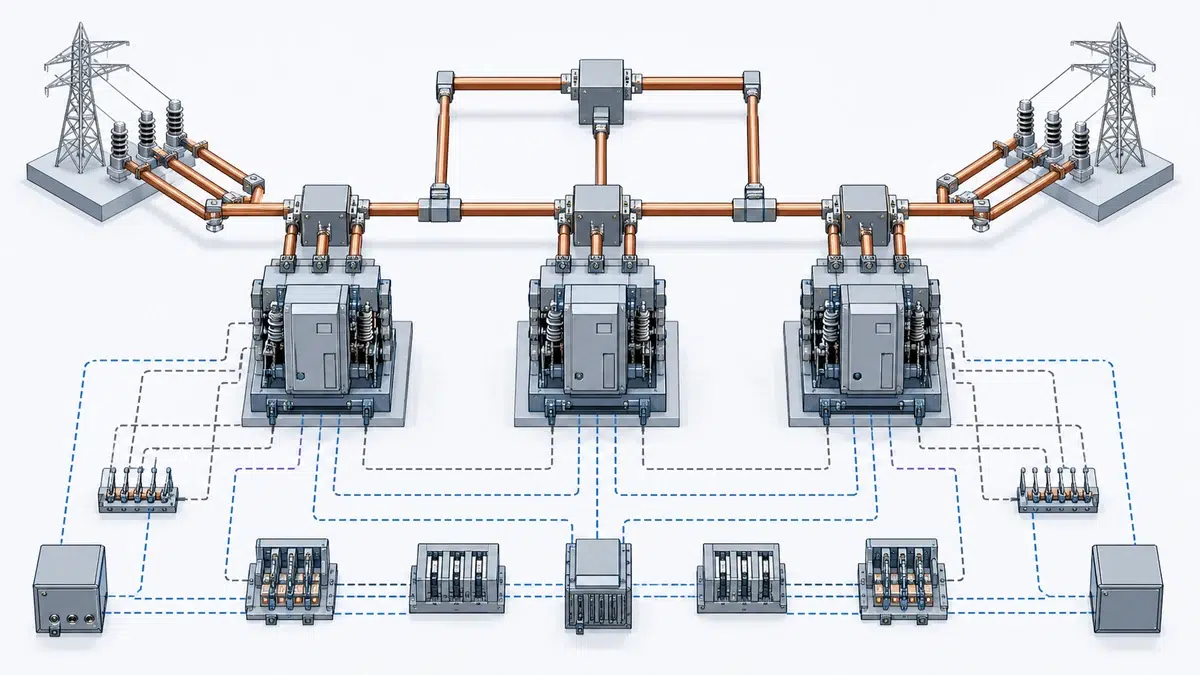
Последовательность перевода VCB начинается с подтверждённых данных, а не предположений. Контроллер или ПЛК (PLC) должен определять исправность соответствующих источников, состояние каждого выключателя (открыт или закрыт), нужное положение выкатного выключателя и допустимость операции в выбранном режиме перевода. Руководство ABB по применению AKD10 описывает входы ПЛК (PLC) схемы перевода: напряжение источника, состояние вводного и секционного выключателей, положение выкатного выключателя и режим перевода. Эти сигналы служат основой для выбора команды отключения, включения или запрета перевода.
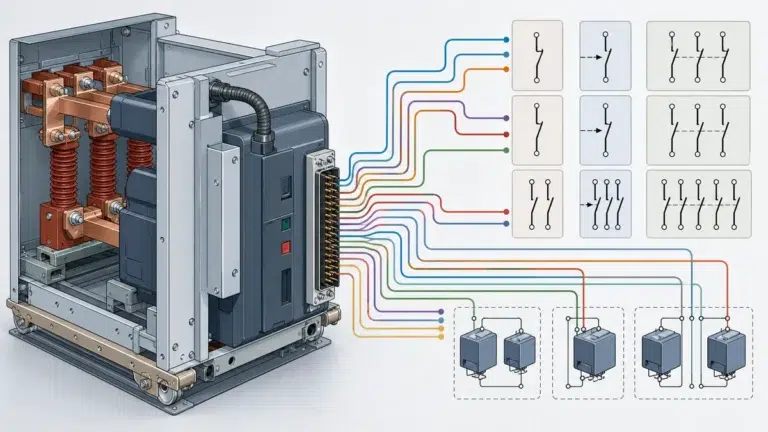
Обратную связь выключателей нельзя считать только индикацией. Контакты состояния вводного и секционного выключателей подтверждают, выполнило ли физическое устройство команду. Контакты положения «вкатан/выкачен» особенно важны для выкатных VCB: выкаченный выключатель или выключатель в испытательном положении может быть недоступен для работы в режиме эксплуатации. Рекомендации ABB ATS предусматривают соответствующие контакты обратной связи и контакт положения «вкатан/выкачен» для выкатных выключателей, подтверждая, что физическое положение входит в цепь разрешений перевода.
При практической проверке для каждого сигнала обратной связи следует установить, какое состояние он представляет, на какую логическую операцию влияет и к чему приведёт его отказ. Если главный VCB показывает замкнутое состояние, цепь включения секционного VCB должна учитывать его согласно принятой проектом философии блокировок. Если секционный VCB не находится в требуемом положении, логика не должна считать его готовым к переводу нагрузки. При отсутствии или ненормальном сигнале напряжения источника последовательность должна выполнить предусмотренную блокировку или запрет, а не продолжать работу вслепую.
Основная цель блокировок — исключить небезопасное или непредусмотренное состояние коммутации. В рекомендациях ABB AKD10 описана блокировка вводных и секционных выключателей для предотвращения параллельного соединения источников. В типичной схеме «ввод—ввод—секционный выключатель» система управления не должна выдавать команду на включение секционного VCB, если оба вводных VCB уже замкнуты, кроме случая специально спроектированного перехода с кратковременной параллельной работой. При переводе с разрывом питания один вводной выключатель следует отключить до разрешения включения секционного или резервного выключателя.
Блокировки следует рассматривать на двух уровнях. Первый — логическая блокировка в ПЛК (PLC), реле, устройстве перевода или контроллере. Она оценивает напряжение, состояние выключателей, режим перевода и другие входы перед выдачей команд отключения или включения. Второй уровень — жёсткая электрическая блокировка в цепях включения VCB. В руководстве ABB AKD10 описаны жёсткие электрические блокировки с применением вспомогательных и позиционных контактов выключателей в цепях включения. Это важно, поскольку один программный выход или выход контроллера не должен быть единственным препятствием ошибочной команде включения.
В зависимости от логики переключения и конструкции оборудования может потребоваться также механическая блокировка. В рекомендациях ABB ATS предусматривается механическая блокировка, если она требуется логикой переключения. Для систем VCB необходимость следует определять по фактической схеме, расположению выключателей, выкатной конструкции, связи источников и проектной философии управления. Механические, жёсткие электрические и логические блокировки должны соответствовать предусмотренной последовательности и не противоречить друг другу. Используйте линейкой средневольтных VCB для предварительного сопоставления доступного оборудования с режимом проекта до запроса окончательной конфигурации.
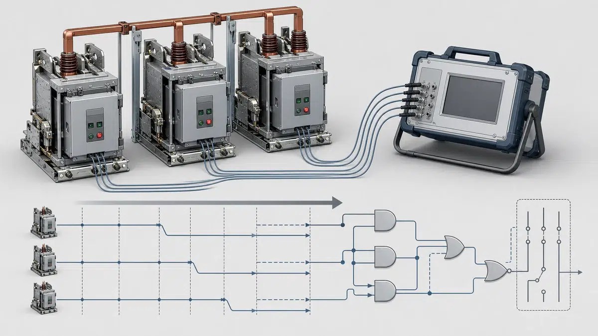
Схема перевода шин должна определять и условия, при которых перевод выполнять нельзя. Согласно Siemens, устройство быстрого перевода контролирует напряжение основного ввода, шин электродвигателей и резервного источника и может блокировать перевод при повреждении шин, ручном отключении выключателя, выкаченном выключателе или испытательном положении, проблемах цепей ТН (PT), повреждении нагрузки или провале напряжения. В рекомендациях ABB AKD10 также указано, что перевод может блокироваться при отключении вводного или секционного выключателя защитой от повреждения. Это показывает, что блокировка перевода — не дополнительная функция, а часть защитных границ последовательности.
Отключение защитой при повреждении особенно важно. Если вводной или секционный VCB отключился из-за повреждения, автоматический перевод может подать питание на повреждённый участок от другого источника, если логика не заблокирует операцию. То же относится к обнаружению повреждения шин и повреждениям нагрузки. Система перевода должна отличать потерю источника от повреждения ниже по цепи или на шинах, при котором повторная подача питания недопустима.
Ещё одно важное условие — ручное отключение выключателя. В рекомендациях Siemens ручное отключение включено в число причин блокировки перевода. Это не позволяет системе автоматически отменять преднамеренное действие оператора. Аналогично выкаченное/испытательное положение и неисправности цепей ТН (PT) могут сделать обратную связь ненадёжной или выключатель недоступным. В таких случаях безопаснее запретить перевод до устранения и проверки условия.
Проверка последовательности подтверждает выполнение заданного порядка операций и правильную реакцию каждого разрешающего и блокирующего условия. Для схемы перевода шин VCB следует проверить наличие источников, положение выключателей, выходы включения и отключения, обратную связь вспомогательных контактов, сигналы положения выкатного выключателя, выбранный режим и блокировку перевода. Необходимо подтвердить как нормальный ход, так и отказ от операции.
Базовая проверка перевода с разрывом питания должна подтвердить контроль выбранного основного и резервного источников, фиксацию отключения главного VCB и отсутствие команды на включение секционного или резервного VCB до выполнения необходимых разрешающих условий. Следует также подтвердить, что логика не допускает параллельного соединения источников, если схема предназначена для его предотвращения. В руководстве ABB AKD10 прямо описана блокировка вводного и секционного выключателей для предотвращения параллельной работы источников, поэтому это ключевой пункт проверки.
Проверка должна охватывать ненормальные случаи, а не только успешный перевод. В примерах из указанных рекомендаций изготовителей — выкаченное/испытательное положение выключателя, проблема цепи ТН (PT), повреждение шин, повреждение нагрузки, ручное отключение выключателя, отключение защитой при повреждении и отсутствие напряжения источника. До испытания для каждого случая следует определить ожидаемое действие: блокировка перевода, запрет включения, отключение выключателя, сигнализация или сохранение текущего состояния согласно утверждённому проекту. При проверке номинальных параметров сопоставьте условия с справочные данные о номинальных параметрах VCB.
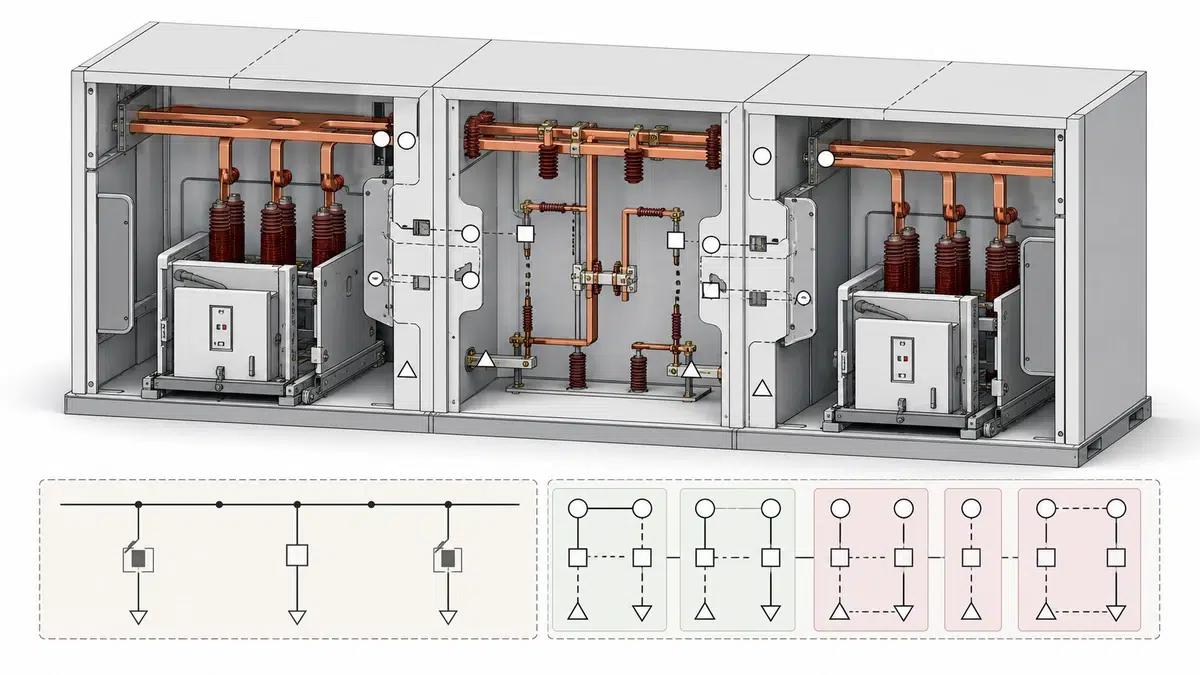
Проверки жёсткой цепи включения подтверждают, что физическая цепь VCB соблюдает те же правила, что и логика управления. В руководстве ABB AKD10 описаны жёсткие электрические блокировки с использованием вспомогательных и позиционных контактов выключателя в цепях включения. Следовательно, цепь включения может требовать подтверждения, что другой выключатель отключён, выключатель находится в нужном положении или схема допускает включение. Ненормальный результат включения или отключения следует проверять по руководство по поиску неисправностей при включении и отключении VCB а не устранять как обычный общий дефект.
Полезный метод проверки — пройти всю цепочку разрешений включения от входа до выхода. Если вспомогательный контакт главного VCB показывает замкнутое положение, цепь включения секционного VCB должна реагировать согласно проекту блокировок. Если позиционный контакт секционного VCB показывает, что выключатель не вкатан должным образом, команда включения не должна выполняться. Если контроллер выдаёт сигнал включения при отсутствии жёстко подключённого разрешения, VCB не должен включиться.
Это различие важно при поиске неисправности. Неудачный перевод может быть вызван тем, что ПЛК (PLC) не выдал команду включения, либо тем, что ПЛК (PLC) выдал её, но жёсткая цепь включения заблокировала операцию. В протоколе проверки это различие должно быть видно по состоянию выхода контроллера, разрешений цепи включения и реакции выключателя.
Режим перевода входит в границы логики. В руководстве ABB AKD10 режим перевода указан среди входов ПЛК (PLC), то есть выбранный режим непосредственно влияет на разрешение перевода и выдачу команд. Одна и та же схема выключателей может работать по-разному в автоматическом, ручном, испытательном или ином режиме, определённом проектом.
Следует также учитывать намерение оператора. В рекомендациях Siemens ручное отключение выключателя указано как условие, способное блокировать перевод. Это важно, поскольку автоматическая система не должна считать каждое отключённое положение признаком потери источника. Если оператор намеренно отключил VCB для обслуживания или по эксплуатационным причинам, автоматическое повторное включение или перевод может создать опасное либо нежелательное состояние, если схема не распознаёт и не блокирует такое действие.
Проверка режима должна охватывать правильность индикации, разрешений и отказа от операции. Следует подтвердить, что автоматический перевод активен только в предусмотренном режиме, ручные операции не запускают перевод случайно, а испытательное или выкаченное положение не имитирует готовность к работе.
Комплект подтверждения схемы перевода шин VCB должен связывать принципиальную логику, логику ПЛК (PLC) или устройства, полевую проводку и фактическую работу выключателей. Как минимум, следует указать входы напряжения источников, сигналы состояния главного и секционного VCB, входы положения выкатного выключателя и режима перевода, выходы включения и отключения, контакты жёстких блокировок и условия запрета. Эти пункты соответствуют функциям из рекомендаций ABB и Siemens без предположений о номиналах или времени конкретного проекта.
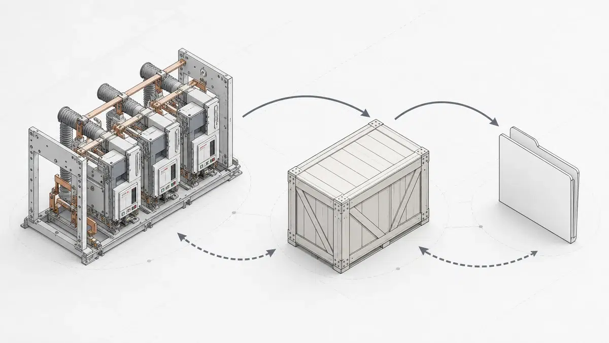
В подтверждении приёмки следует указать, что проверялось, какое условие имитировалось или подавалось, какой выход ожидался и как фактически сработал VCB. Например, если включение секционного VCB блокируется из-за замкнутого главного VCB, запись должна содержать сигнал состояния главного выключателя, результат команды включения секционного и итоговое положение выключателя. Если выключатель находится в испытательном положении, следует зафиксировать блокировку или запрет перевода согласно проекту. Используйте контрольным перечнем приемочных испытаний VCB для прослеживаемости заводских и объектовых данных при передаче.
Наиболее убедительные протоколы проверки охватывают и успешный, и заблокированный перевод. Успешные испытания подтверждают способность схемы восстановить или поддержать питание при выполнении разрешающих условий. Испытания с блокировкой подтверждают отказ от операции при повреждении шин, ручном отключении выключателя, выкаченном/испытательном положении, проблемах цепи ТН (PT), повреждении нагрузки, провале напряжения или отключении защитой, если утверждённая логика требует запрета.
Это логика управления и проводки, определяющая, когда VCB может отключаться или включаться при переводе источника. Она использует такие входы, как напряжение источника, состояние вводного и секционного выключателей, положение выкатного выключателя и режим перевода, и выдаёт команды отключения и включения только при выполнении разрешающих условий. Главные цели — предотвратить непреднамеренное параллельное соединение источников, не допустить повторной подачи питания на повреждённый участок и подтвердить физическую готовность VCB до команды.
Вспомогательные контакты передают в логику перевода сведения об открытом или закрытом положении VCB и могут применяться в жёстких блокировках цепи включения. В рекомендациях ABB описаны жёсткие электрические блокировки с использованием вспомогательных и позиционных контактов в цепях включения. При проверке поведение вспомогательных контактов следует сопоставлять с фактическим положением выключателя, поскольку неверная обратная связь может привести к ошибочному решению системы перевода.
Это состояние, не позволяющее продолжить автоматическую или командную последовательность перевода. В рекомендациях изготовителей приведены такие примеры, как повреждение шин, ручное отключение выключателя, выкаченное или испытательное положение, неисправность цепей ТН (PT), повреждение нагрузки, провалы напряжения и отключение вводного или секционного выключателя защитой. Перевод может быть небезопасен или недопустим даже при наличии резервного источника.
Она подтверждает, находится ли выкатной VCB в требуемом физическом положении для работы в эксплуатации. В рекомендациях ABB ATS предусмотрен контакт «вкатан/выкачен» для выкатных выключателей, а Siemens указывает выкаченное/испытательное положение как условие блокировки перевода. Такая обратная связь не позволяет считать выключатель в выкаченном или испытательном положении готовым к работе в схеме перевода шин.
Это документальное подтверждение того, что схема перевода работает в утверждённом порядке и отказывается от операции при невыполнении обязательных условий. Проверяются контроль источников, состояние выключателей, режим перевода, выходы отключения и включения, жёсткие блокировки, положение выкатного выключателя и условия запрета. Проверка VCB должна включать как нормальные режимы перевода, так и случаи запрета, например отключение защитой, отсутствие напряжения источника, выкаченные выключатели или повреждение шин.