هل تحتاج إلى المواصفات الكاملة؟
قم بتنزيل كتالوج منتجاتنا لعام 2025 للحصول على رسومات تفصيلية ومعايير تقنية لجميع مكونات المفاتيح الكهربائية.
احصل على الكتالوج
قم بتنزيل كتالوج منتجاتنا لعام 2025 للحصول على رسومات تفصيلية ومعايير تقنية لجميع مكونات المفاتيح الكهربائية.
احصل على الكتالوج قم بتنزيل كتالوج منتجاتنا لعام 2025 للحصول على رسومات تفصيلية ومعايير تقنية لجميع مكونات المفاتيح الكهربائية.
احصل على الكتالوج
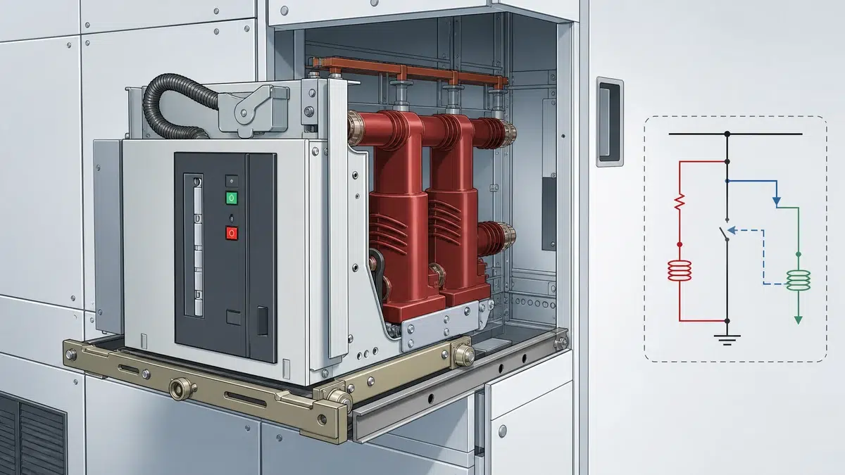
Commissioning a new vacuum circuit breaker panel involves dozens of functional checks, but few carry as much consequence as the **anti-pumping circuit verification VCB** test. When this protective function fails silently, a maintained close signal can drive a breaker into a rapid open-close-open cycle—a condition that stresses contacts, overheats operating coils, and can escalate a fault into catastrophic switchgear damage. This article walks through the purpose of the anti-pump function, the governing documents, a step-by-step field test procedure, and the acceptance criteria engineers should apply before energising any new panel.
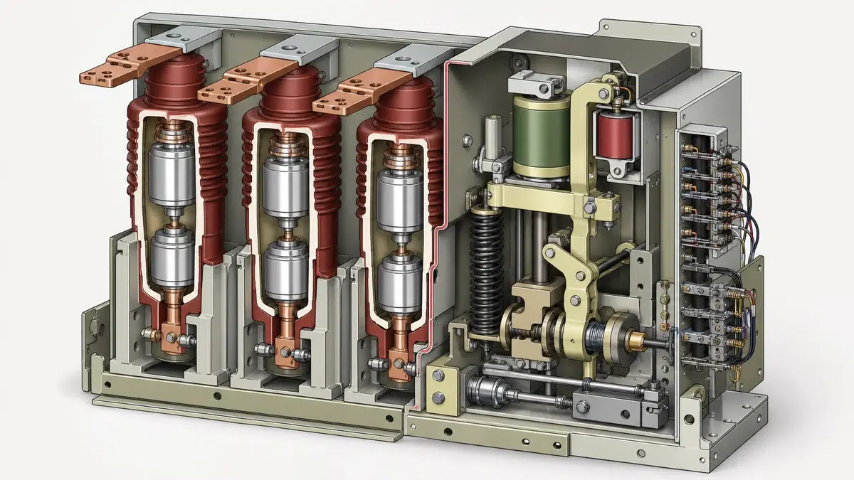
A vacuum circuit breaker closes on command and trips on a fault. If the close pushbutton is held down—or if a control relay contact welds shut—the breaker would immediately attempt to reclose the moment the trip coil opens it. Left unchecked, this creates a pumping cycle: close, trip, close, trip, each operation adding mechanical wear and thermal stress to the operating mechanism and vacuum interrupter. Use the VCB closing and opening troubleshooting guide to separate control-circuit, coil, interlock, and mechanism causes after a failed operation.
The anti-pump (AP) relay breaks this cycle at the control level. According to Schneider Electric's MasterClad MV switchgear documentation, the anti-pump relay prevents repeated open-close cycling under a maintained close signal and permits a new close only after the close circuit has been de-energised and re-energised. That de-energise-and-re-energise requirement is the functional definition every test engineer should memorise before picking up a test lead.
In practical wiring terms, when the AP relay energises on a close command, it inserts a normally-closed contact in series with the close coil circuit. Even if the close signal remains present, the close coil cannot draw current again until the close command is removed, allowing the AP relay to drop out, and a fresh close command is issued.
IEC 62271-100 is the principal international standard covering AC circuit-breakers rated above 1 kV. It establishes type-test requirements, rated characteristics, and performance criteria for the interrupting medium—but it does not prescribe a single wiring topology for the control circuit. For any specific panel, the project-controlled standard and the manufacturer's approved wiring diagram remain the definitive authority.
This distinction matters during anti-pumping circuit verification VCB work. Field engineers sometimes assume that verifying the AP function against a generic schematic is sufficient. It is not. The approved single-line diagram, the relay logic drawing stamped by the original equipment manufacturer (OEM), and any project-specific amendments supersede generic references. Always obtain the as-built drawing set before beginning the test. For equipment and configuration options, compare the project duty with the vacuum circuit breaker options.
Schneider Electric's EvoPact MV CB user guide adds another important nuance: some manufacturers implement anti-pumping mechanically rather than—or in addition to—electrically. Where a mechanical AP latch is present, the approved auxiliary-contact wiring must not defeat that mechanism. Wiring changes made without OEM approval risk nullifying both the electrical and mechanical protections simultaneously, leaving the breaker completely unprotected against pumping.
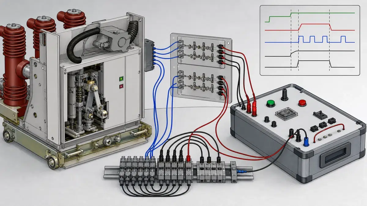
Before performing the anti-pumping circuit verification VCB test, the following preparatory steps are mandatory.
**Obtain the approved drawing set.** Confirm you have the latest revision of the panel wiring diagram, the relay logic diagram, and any project-specific deviations. Cross-check the AP relay model number against the panel schedule.
**Isolate HV components.** The anti-pump test is a low-voltage control-circuit function test. The primary bus must be de-energised, earthed, and proven dead before any work begins inside the cubicle. Follow the site permit-to-work system without exception. For the surrounding cubicle interfaces, use the switchgear parts inspection checklist to keep component checks in the same acceptance record.
**Verify DC auxiliary supply.** The AP relay operates on the panel's control voltage—typically 110 V DC or 220 V DC. Confirm that the correct supply rail is live and within tolerance (usually ±10 % of nominal) at the breaker control terminal block.
**Confirm breaker mechanism is reset.** The breaker must be in the fully charged and open state. An uncharged spring mechanism will prevent the close coil from operating, making the test inconclusive.
**Identify the AP relay.** Locate the anti-pump relay on the panel wiring diagram, physically identify it in the relay rack or terminal strip, and record its model number, coil voltage, and the specific contact numbers used in the close coil circuit.
**Prepare test equipment.** You will need a DC voltmeter, a test lamp or current tracer, a temporary short link or jumper lead rated for the control voltage, and a stopwatch or digital timer. Document each item in the test record.
The procedure below applies to a standard electrical AP relay implementation. If the panel employs a mechanical AP mechanism, supplement this procedure with the OEM's mechanical latch check before executing the electrical steps.
**Step 1 — Baseline close operation.** Apply a momentary close command (pulse ≤ 2 s) via the local control switch. Confirm the breaker closes and the AP relay energises. Record close time from relay indication or auxiliary contact state.
**Step 2 — Confirm AP relay is latched.** While the breaker is closed, verify that the AP relay remains energised by checking the coil voltage across its terminals. The relay must hold on the breaker's 52a (closed) auxiliary contact in the AP holding circuit. Measure and record the voltage.
**Step 3 — Simulate a maintained close signal.** Apply and hold a continuous close command. The breaker is already closed; no operation should occur. Record that the close coil is de-energised with the AP contact interrupting the circuit.
**Step 4 — Trip the breaker under maintained close signal.** Issue a trip command while maintaining the close signal. The breaker must open and must not reclose. This is the critical test: the AP relay, still energised via its holding circuit, must block the close coil from picking up. Confirm the breaker has opened and remained open. Record the open position on the auxiliary contact indication.
**Step 5 — Verify the block persists.** Hold the close command for at least 5 seconds after the breaker has tripped. Confirm throughout this period that the close coil current is zero (voltmeter across close coil shows full supply voltage if circuit is open, or use a clamp meter to confirm zero coil current). The breaker must not reclose.
**Step 6 — Remove and re-apply close command.** Release the close command. Confirm the AP relay drops out. Then re-apply a momentary close command. The breaker must close normally. This confirms that the anti-pump function resets correctly when the close signal is properly cycled.
**Step 7 — Repeat from local and remote.** Steps 1 through 6 must be performed independently from both the local control panel and the remote SCADA or substation control interface. A relay that blocks local pumping but passes through a remote signal has a wiring defect that must be resolved before energisation.
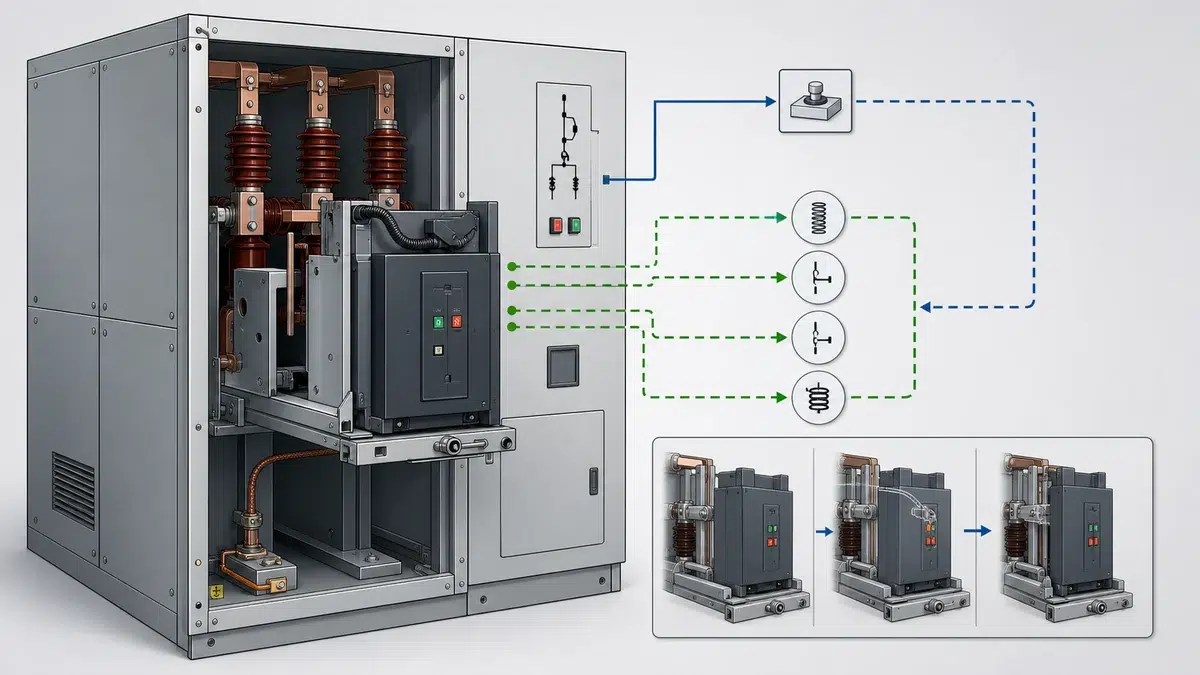
**Step 8 — Document results.** For each step, record the relay terminal voltages, coil current readings, and breaker position indication. Note the time stamp, the technician performing the test, and the drawing revision used. Any deviation from expected behaviour is a nonconformance and must be raised through the project's corrective-action process before the panel is submitted for energisation approval. The VCB factory and site acceptance checklist provides a companion structure for acceptance criteria, results, and closeout records.
A panel passes the anti-pumping circuit verification VCB test only when all of the following conditions are satisfied without exception:
1. The breaker does not reclose after tripping under a maintained close signal, in either local or remote control mode.
2. The AP relay energises on every close command and de-energises only when the close command is removed.
3. The close coil current is confirmed zero while the AP relay is latched and a close command is maintained.
4. Normal close operation is restored after the close command is cycled, confirming the function is not latched permanently.
5. All measured control voltages are within the tolerance band specified on the approved wiring diagram.
Common failure modes discovered during this test include:

Any of these failure modes demands an engineering investigation, a drawing revision, a physical wiring correction, and a full re-test before the test record is closed.
The anti-pump relay prevents a vacuum circuit breaker from repeatedly closing and opening under a maintained close signal. When a breaker trips on a fault while the close command is still present, the AP relay blocks the close coil from re-energising until the operator removes and re-applies the close command. This protects the vacuum interrupter, the operating mechanism, and the upstream system from the mechanical and thermal damage caused by rapid successive operations.
Electrical anti-pumping uses a dedicated relay with contacts wired in series with the close coil circuit. Mechanical anti-pumping uses a latch within the breaker's operating mechanism that physically prevents a reclose until the close command resets. Some manufacturers, including those whose products follow the EvoPact design philosophy, implement both methods simultaneously. Where both exist, the control-circuit wiring must be reviewed against the OEM documentation to ensure the electrical wiring does not inadvertently defeat the mechanical latch.
IEC 62271-100 is the primary international standard for AC circuit-breakers rated above 1 kV. It defines type-test requirements, rated characteristics, and performance criteria. However, IEC 62271-100 does not dictate the precise wiring topology of the control circuit. For any specific installation, the project-controlled standard and the manufacturer's approved wiring diagram take precedence and must be followed when performing anti-pumping circuit verification VCB tests in the field.
After the breaker has tripped under a maintained close signal and the AP block has been confirmed, the correct reset sequence is: first, remove the close command completely; second, confirm the AP relay drops out by measuring zero coil voltage or by observing the relay indicator; third, re-apply a fresh momentary close command. The breaker must close normally on this fresh command. If the breaker does not close, the AP holding circuit may have a wiring fault, the relay coil may be faulty, or the 52a auxiliary contact may have failed open.
Skipping the AP verification leaves the panel exposed to an undetected wiring or relay fault that will only manifest during a real fault event—the worst possible moment. Under those conditions, a pumping breaker subjects the vacuum interrupter to repeated interruption duty in rapid succession, accelerating contact erosion, potentially welding contacts, and generating voltage transients that can damage instrument transformers, protection relays, and cables. The failure can escalate a manageable fault into a switchgear fire or forced outage lasting days. The time cost of the verification test—typically under two hours—is negligible against that risk.