هل تحتاج إلى المواصفات الكاملة؟
قم بتنزيل كتالوج منتجاتنا لعام 2025 للحصول على رسومات تفصيلية ومعايير تقنية لجميع مكونات المفاتيح الكهربائية.
احصل على الكتالوج
قم بتنزيل كتالوج منتجاتنا لعام 2025 للحصول على رسومات تفصيلية ومعايير تقنية لجميع مكونات المفاتيح الكهربائية.
احصل على الكتالوج قم بتنزيل كتالوج منتجاتنا لعام 2025 للحصول على رسومات تفصيلية ومعايير تقنية لجميع مكونات المفاتيح الكهربائية.
احصل على الكتالوج
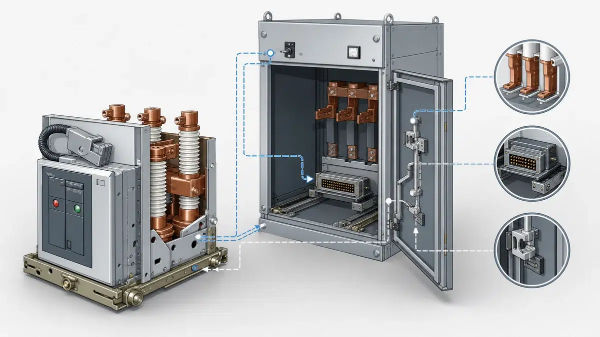
ينبغي ألا تتعامل ورقة بيانات طلب عرض السعر (RFQ) الخاصة بـVCB مع دائرة التحكم باعتبارها قائمة عامة بالملحقات. ففي قواطع الدائرة الفراغية متوسطة الجهد، تحدد ملفات الإغلاق والفصل والتلامسات المساعدة ووظيفة منع الضخ ومحرك شحن الزنبرك وتلامسات الحجب وتشابكات السحب والتشابكات من جانب المفاتيح الكهربائية ما إذا كان القاطع يستطيع الإغلاق والفتح والاختبار والسحب والاندماج بأمان مع منطق اللوحة.
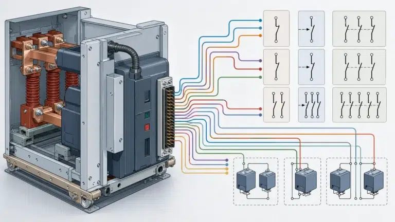
لصياغة مواصفة واضحة لتشابكات دائرة التحكم الخاصة بـVCB في RFQ، ينبغي للمشتري أن يطلب من الموردين تحديد كل جهاز في دائرة التحكم، وكل تلامس سماح أو حجب، وكل واجهة بين القاطع والمفاتيح الكهربائية. ولا ينبغي أن تفترض RFQ أن جميع علامات VCB التجارية تستخدم أسماء أطراف أو ترتيبات تشابك متطابقة. وتوضح وثائق ABB الخاصة بقاطعي VD4X وSecoVac، وإرشادات Schneider للمساعدات الكهربائية EvoPacT، ووثائق Siemens الخاصة بـVCB أن وظائف التحكم والتشابك موزعة بين المساعدات المركبة على القاطع ومشغلات الفصل والمحركات ودوائر منع الضخ والأقفال الميكانيكية وواجهات العربة أو السحب ومنطق الموضع في المفاتيح الكهربائية.
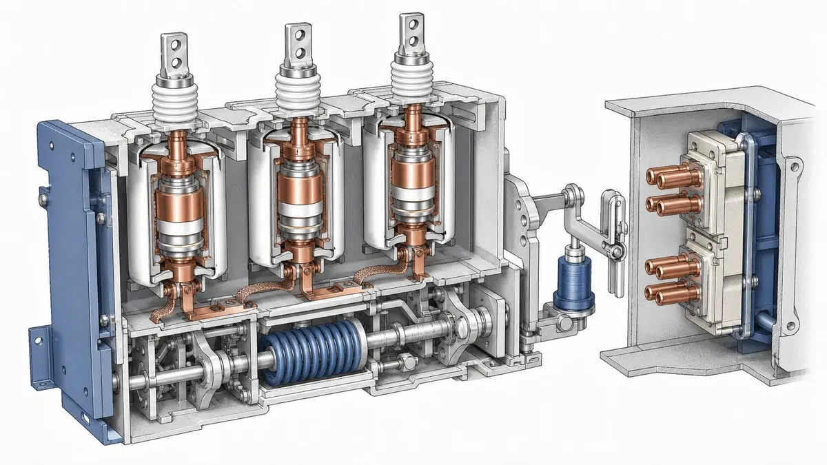
ينبغي أن تطلب ورقة بيانات RFQ جدولاً مخصصاً لدائرة التحكم في VCB. وعلى الأقل، يحدد المورد ما إذا كان كل عنصر مشمولاً، وكيفية تعريفه في المخطط، وأين تنتهي توصيلاته.
| حقل RFQ | ما يجب على المورد التصريح به | لماذا هذا مهم |
|---|---|---|
| محرر الإغلاق / ملف الإغلاق | رمز الجهاز ومراجع الأطراف ومسار أمر التشغيل وتلامسات الحجب المتسلسلة | تحدد وثائق ABB VD4X وSecoVac محررات الإغلاق أو ملفات الإغلاق بوصفها عناصر أساسية في دائرة التحكم. |
| محرر الفصل التحويلي / ملف الفصل | العدد ورموز الأجهزة ومراجع الأطراف ومسار أمر الفصل | يميز ABB VD4X محررات الفصل التحويلية، بينما تصف SecoVac ملفات الفصل ضمن دائرة التحكم. |
| مرحل منع الضخ أو وظيفة منع الضخ | رمز الجهاز وموقعه المنطقي وتفاعله مع أمر الإغلاق | تشير وثائق ABB VD4X وSecoVac إلى مرحلات منع الضخ؛ وتحذر Schneider من أن خيارات التوصيل قد تعطل وظيفة منع الضخ الميكانيكية. |
| محرك شحن الزنبرك | أطراف المحرك ومسار التغذية وتلامسات الحماية أو التحكم وواجهة بيان شحن الزنبرك | تحدد وثائق ABB VD4X وSecoVac محرك شحن الزنبرك بوصفه جزءاً من دائرة التحكم بالقاطع. |
| تلامسات مساعدة للآلية | عدد التلامسات وحالتها الطبيعية ووظيفتها ومراجع الأطراف | يميز ABB VD4X التلامسات المساعدة للآلية؛ وتشير SecoVac إلى المفتاح المساعد 52. |
| تلامسات مغناطيس الحجب | بيان ما إذا كانت مستخدمة وموضعها في الدائرة والحالة التي تتحكم بها | يميز ABB VD4X تلامسات مغناطيس الحجب في دائرة التحكم بالقاطع. |
| تلامسات مساعدة لتشابك أزرار الضغط | بيان ما إذا كانت موردة ووظيفة التلامسات وتفاعلها مع أزرار الإغلاق والفتح المحلية | يعرف ABB VD4X تلامسات تشابك أزرار الضغط المساعدة بشكل منفصل عن غيرها من التلامسات المساعدة. |
| تلامس حجب الإغلاق | رمز التلامس وظروف تشغيله وما إذا كان يمنع الإغلاق الكهربائي | تصف ABB SecoVac تلامس حجب للإغلاق في دائرة الإغلاق والتشابك. |
| تشابكات العربة أو السحب أو موضع القاطع القابل للسحب | تلامسات أو واجهات ميكانيكية مرتبطة بمواضع الاختبار/الخدمة/الفصل | تصف ABB SecoVac مكونات اختيارية لتشابك العربة وتشابكات فصل إيجابية وسلبية مرتبطة بالسحب. |
| تشابكات جانب المفاتيح الكهربائية | واجهة تشابك مع فاصل أو مفتاح تأريض أو لوحة | توثق Siemens تشابك VCB عبر آليات الفاصل أو مفتاح التأريض في جانب المفاتيح الكهربائية. |
ينبغي أن تطلب RFQ المخطط الفعلي للمورد بدلاً من الاكتفاء بعبارة في الكتيب مثل «دائرة تحكم قياسية». كما ينبغي أن تطلب ورقة البيانات من المورد تحديد التلامسات المركبة على القاطع وتلك المركبة على العربة أو المفاتيح الكهربائية.
دائرة الإغلاق هي الجزء من مخطط التحكم في VCB الذي يؤدي فيه غموض RFQ غالباً إلى مخاطر الشراء. تصف وثائق ABB SecoVac دائرة إغلاق وتشابك تضم ملف إغلاق ومرحل منع الضخ وتلامس حجب الإغلاق والمفتاح المساعد 52 ومحرك شحن الزنبرك وملفات الفصل ومكونات حجب وتشابك العربة الاختيارية. كما تميز وثائق ABB VD4X محرر الإغلاق والتلامسات المساعدة وتلامسات مغناطيس الحجب وتلامسات تشابك أزرار الضغط المساعدة ومحرك شحن الزنبرك ومحررات الفصل التحويلية ومرحل منع الضخ. راجع خيارات قاطع الدائرة المفرغ كنقطة بداية عملية لمطابقة صيغة القاطع المطلوبة مع التطبيق.
لذلك ينبغي أن تتضمن RFQ حقول دائرة الإغلاق التالية:
| حقل دائرة الإغلاق | الإدخال المطلوب في RFQ |
|---|---|
| مصدر أمر الإغلاق الكهربائي | محلي أو عن بُعد أو كلاهما، حسب متطلبات المشروع |
| رمز محرر / ملف الإغلاق | رمز الجهاز الدقيق لدى المورد ومرجع المخطط |
| مسار تلامسات أمر الإغلاق | جميع التلامسات المتسلسلة مع أمر الإغلاق، بما فيها تلامسات السماح والحجب |
| جهاز منع الضخ | وظيفة قائمة على مرحل أو آلية، مع موقعها في المخطط |
| تلامس حجب الإغلاق | بيان ما إذا كانت مشمولة وظروف تشغيلها |
| سماح شحن الزنبرك | بيان ما إذا كان الإغلاق يعتمد على الطاقة المخزنة أو مؤشر شحن الزنبرك |
| تفاعل المفتاح المساعد | توضيح كيفية استخدام المفتاح المساعد 52 أو تلامسات الآلية في مسار الإغلاق |
| تشابك أزرار الضغط | بيان ما إذا كانت تلامسات تشابك أزرار الضغط المحلية مشمولة |
| واجهة المحطة الطرفية | أرقام الأطراف لتوصيل أمر الإغلاق من العميل |
| متطلبات رسومات المورد | تقديم المخطط العنصري الكامل ومخطط الأطراف مع العرض |
ينبغي ألا تحدد ورقة البيانات بنية دائرة غير موثقة. بل يجب أن تطلب من المورد إظهار البنية الفعلية وتحديد كل عنصر سماح أو حجب.
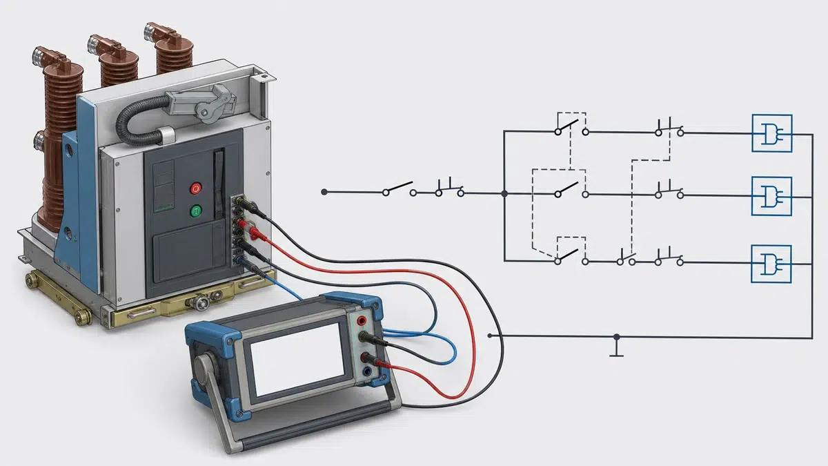
منع الضخ ليس مجرد اسم مرحل في قائمة قطع. بل هو متطلب وظيفي لمنع محاولات الإغلاق المتكررة عند استمرار أمر الإغلاق بعد الفصل أو فشل تسلسل الإغلاق. وتشير وثائق ABB VD4X وSecoVac إلى مرحلات منع الضخ في دائرة التحكم بالقاطع، بينما تضيف إرشادات Schneider تنبيهاً مهماً بشأن التوصيل: يجب ألا توصل التلامسات المساعدة الخاصة بالقاطع على التوالي مع محرر الإغلاق وتلامس الإغلاق بطريقة تعطل نظام منع الضخ الميكانيكي. وتميز Schneider هذا الترتيب غير الآمن عن التشابك عبر تلامسات مساعدة لقواطع أخرى. إن دليل تصنيفات VCB واختياره على تحويل واجب النظام إلى بيانات القاطع الواجب التحقق منها.
لذلك ينبغي للمشتري إدراج تصريح محدد بشأن منع الضخ في RFQ بدلاً من افتراض أنه قياسي.
| حقل RFQ لمنع الضخ | التصريح المطلوب |
|---|---|
| طريقة منع الضخ | على المورد تحديد المرحل أو وظيفة الآلية أو الترتيب المركب المستخدم |
| موضع وظيفة منع الضخ في المخطط | على المورد إظهار الوظيفة في مخطط التحكم |
| سلوك أمر الإغلاق المستمر | على المورد وصف كيفية منع الإغلاق المتكرر |
| قيد استخدام التلامسات المساعدة الخاصة بالقاطع | على المورد تأكيد أن التلامسات المساعدة للقاطع لا تستخدم بطريقة تعطل منع الضخ |
| التشابك مع قاطع آخر | على المورد تحديد أي تشابك عبر التلامسات المساعدة لقواطع أخرى إذا طلبه المشروع |
| مرجع الاختبار | على المورد تضمين التحقق من منع الضخ في إجراء FAT أو الاختبار الوظيفي عند الطلب |
هذا حقل إلزامي لتشابك دائرة التحكم في RFQ الخاصة بـVCB، لأن إدراج مرحل منع الضخ رسمياً لا يثبت بحد ذاته أن التوصيلات النهائية تحافظ على سلوك منع الضخ المقصود.
ينبغي توثيق دوائر الفصل بشكل منفصل عن دائرة الإغلاق. تميز وثائق ABB VD4X محررات الفصل التحويلية، بينما تصف وثائق ABB SecoVac ملفات الفصل في دائرة التحكم بالقاطع. كما تصف SecoVac تشابكات فصل إيجابية وسلبية مرتبطة بالسحب؛ لذلك لا ينبغي أن تتعامل RFQ الخاصة بـVCB القابل للسحب مع السحب باعتباره ميزة ميكانيكية للوحة فحسب.
ينبغي أن تطلب RFQ الحقول التالية:
| حقل الفصل والسحب | الإدخال المطلوب في RFQ |
|---|---|
| عدد ملفات الفصل | على المورد بيان العدد ورموز الأجهزة |
| مراجع أطراف ملفات الفصل | على المورد تقديم أرقام الأطراف ومراجع المخططات |
| تعريف محرر الفصل التحويلي | على المورد تحديد أجهزة الفصل التحويلية حيثما ينطبق |
| مصادر أوامر الفصل الكهربائية | مصادر الأوامر المحلية أو عن بعد أو من مرحل الحماية أو المحددة للمشروع |
| تشابك الفصل المرتبط بالسحب | على المورد بيان ما إذا كانت تشابكات الفصل الإيجابية أو السلبية مشمولة |
| مكونات تشابك العربة | على المورد تحديد مكونات الحجب أو تشابك العربة الاختيارية إن وجدت |
| الاعتماد على الموضع | على المورد بيان ما إذا كانت سماحات الفصل أو الإغلاق تعتمد على موضع الخدمة أو الاختبار أو الفصل |
| إجراءات الاختبار | على المورد تضمين فحوص وظيفية لسلوك الفصل وتشابك السحب عند الطلب |
ينبغي ألا تفرض RFQ أعداد ملفات فصل أو أرقام أطراف غير متحقق منها. بل يجب أن تطلب من المورد التصريح بها وتقديم المخططات العنصرية ومخططات الأطراف الفعلية.
تصف وثائق Siemens التشابكات الكهربائية والميكانيكية في VCB، بما فيها تشابك الفاصل أو مفتاح التأريض من جانب المفاتيح الكهربائية عبر آليات القفل المغناطيسي ومنع الإغلاق الميكانيكي والكهربائي المعتمد على الموضع. وهذه الأدلة مهمة لأن RFQ التي تطلب فقط «تشابك كهربائي مشمول» قد تغفل الحدود بين VCB والمفاتيح الكهربائية. ولتخطيط الشهود والسجلات، طابق الأدلة مع قائمة التحقق من القبول المصنعي والموقعي لـ VCB.
ينبغي أن تقسم ورقة البيانات التشابكات إلى وظائف مركبة على القاطع أو العربة أو المفاتيح الكهربائية.
| فئة التشابك | حقول RFQ الإلزامية |
|---|---|
| تشابكات كهربائية مركبة على القاطع | مغناطيسات الحجب وتلامسات حجب الإغلاق وتلامسات تشابك أزرار الضغط والتلامسات المساعدة |
| تشابكات ميكانيكية مركبة على القاطع | منع الإغلاق الميكانيكي أو حجب أزرار الضغط المحلية أو وظائف القفل القائمة على الآلية |
| تشابكات العربة أو السحب | تلامسات الموضع ومكونات تشابك العربة وتشابكات الفصل المرتبطة بالسحب |
| تشابكات جانب المفاتيح الكهربائية | واجهات الفاصل أو مفتاح التأريض أو باب اللوحة أو القفل المغناطيسي عند الحاجة |
| منع الإغلاق المعتمد على الموضع | على المورد بيان المواضع التي تسمح بالإغلاق الميكانيكي والكهربائي أو تمنعه |
| مسؤولية الأطراف | على المورد تحديد ما إذا كانت التلامسات تنتهي عند مجموعة أطراف القاطع أو العربة أو المفاتيح الكهربائية |
| مسؤولية التنسيق | على المورد تحديد التشابكات المضمنة ضمن توريد VCB وتلك التي يوفرها مصنع اللوحة |
لشراء VCB، يتمثل النهج الأكثر أماناً في طلب مصفوفة تشابك مكتملة. وعلى المورد تصنيف كل حالة على أنها سماح بالإغلاق أو حجب للإغلاق أو بدء فصل أو بيان فقط أو غير منطبق.
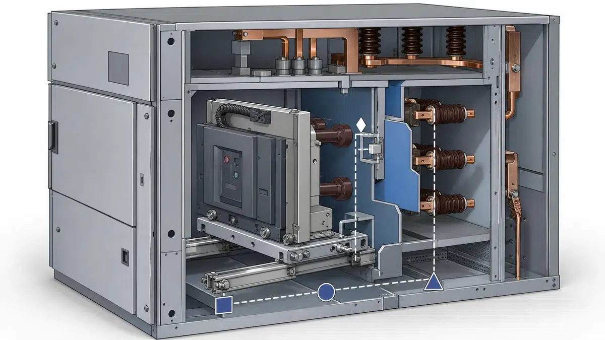
لا يمكن اعتبار التلامسات المساعدة قابلة للتبادل ما لم تُحدد وظيفتها وحالتها الطبيعية وتوقيتها. تميز وثائق ABB VD4X التلامسات المساعدة للآلية وتلامسات مغناطيس الحجب وتلامسات تشابك أزرار الضغط المساعدة. وتشير وثائق ABB SecoVac إلى المفتاح المساعد 52. كما تبرز إرشادات Schneider ضرورة التعامل بعناية مع التلامسات المساعدة الخاصة بالقاطع عند استخدامها قرب محرر الإغلاق وتلامس الإغلاق. إن دليل تعليمات ABB VD4X بوصفه المصدر الأساسي للمتطلب الخاص بالمنتج المذكور هنا.
ينبغي أن تطلب RFQ جدول تلامسات يتضمن الحقول التالية:
| حقل التلامس المساعد | الإدخال المطلوب في RFQ |
|---|---|
| هوية التلامس | رمز المورد، مثل مساعد الآلية أو المفتاح المساعد 52 أو تلامس الحجب أو تلامس تشابك زر الضغط |
| الوظيفة | بيان أو سماح أو حجب أو وظيفة مرتبطة بمنع الضخ أو التشابك |
| تعريف الحالة الطبيعية | تحديد الحالة بالنسبة إلى القاطع المفتوح/المغلق، وموضع العربة عند الاقتضاء |
| الكمية المتاحة | على المورد بيان عدد التلامسات الاحتياطية والمستخدمة |
| موضع التلامس | القاطع أو الآلية أو العربة أو المفاتيح الكهربائية |
| وجهة التوصيل | دائرة داخلية أو طرف العميل أو واجهة المفاتيح الكهربائية |
| القيود | على المورد بيان أي قيود على استخدام التلامس في دائرة الإغلاق |
| مرجع الرسم | مرجع خط المخطط والطرف بدقة |
ينبغي ألا تكتفي RFQ بطلب «تلامسات مساعدة NO/NC». بل يجب أن تطلب تحديد وظيفة كل تلامس كي لا يُساء فهم مخطط التحكم أثناء هندسة اللوحة.
يمكن أن يجمع جدول RFQ عملي الحقول الإلزامية لدائرة التحكم والتشابكات في جدول واحد يستكمله المورد. ويمكن للمشتري إصدار الجدول مع خانات «يستكملها المورد» بدلاً من إدخال قيم مفترضة.
| لا. | حقل ورقة البيانات | الرد المطلوب من المورد |
|---|---|---|
| 1 | مخطط تحكم VCB | تقديم المخطط العنصري الكامل |
| 2 | مخطط الأطراف | تقديم مراجع أطراف العميل |
| 3 | محرر الإغلاق / ملف الإغلاق | تحديد الرمز والأطراف ومسار الدائرة |
| 4 | محرر الفصل التحويلي / ملف الفصل | تحديد الرمز والأطراف ومصادر الأوامر |
| 5 | مرحل أو وظيفة منع الضخ | تحديد الطريقة وموقعها في المخطط |
| 6 | محرك شحن الزنبرك | تحديد الأطراف وتلامسات التحكم |
| 7 | تلامسات مساعدة للآلية | تقديم جدول التلامسات ووظائفها |
| 8 | المفتاح المساعد 52 | تحديد التلامسات المستخدمة في دوائر الفصل أو الإغلاق أو البيان أو التشابك |
| 9 | تلامسات مغناطيس الحجب | بيان ما إذا كانت مشمولة والحالة التي تحجبها |
| 10 | تلامسات مساعدة لتشابك أزرار الضغط | بيان ما إذا كانت مشمولة وكيف تؤثر في التشغيل المحلي |
| 11 | تلامس حجب الإغلاق | تحديد التلامس وحالة التشغيل وموضعه في الدائرة |
| 12 | تلامس مساعد خاص بالقاطع ضمن مسار الإغلاق | تأكيد أن التوصيل لا يعطل سلوك منع الضخ |
| 13 | تشابك مع تلامس مساعد لقاطع آخر | تحديد ما إذا كان المشروع يتطلب تشابكاً عبر قواطع أخرى |
| 14 | مكونات تشابك العربة | بيان ما إذا كان مشمولاً وتقديم مراجع المخططات |
| 15 | تشابكات فصل مرتبطة بالسحب | بيان ترتيب الفصل الإيجابي أو السلبي إن انطبق |
| 16 | منع الإغلاق المعتمد على الموضع | تحديد سلوك مواضع الخدمة والاختبار والفصل والسحب بحسب الاقتضاء |
| 17 | تشابك الفاصل أو مفتاح التأريض | تحديد الواجهة الكهربائية أو الميكانيكية من جانب المفاتيح الكهربائية |
| 18 | آلية قفل مغناطيسي | بيان ما إذا كانت مستخدمة للتشابك من جانب المفاتيح الكهربائية |
| 19 | منع الإغلاق الميكانيكي | تحديد الظروف التي تمنع الإغلاق فعلياً |
| 20 | منع الإغلاق الكهربائي | تحديد التلامسات أو الدوائر التي تمنع الإغلاق الكهربائي |
| 21 | الفحوص الوظيفية FAT | إدراج فحوص الإغلاق والفصل ومنع الضخ وتشابك الموضع ووظائف الحجب |
| 22 | حدود نطاق التوريد | تحديد ما يورد مع VCB وما يورده مصنع المفاتيح الكهربائية |
يحافظ هذا الجدول على موضوعية RFQ. فهو يطلب من مورد VCB التصريح بالأجهزة والوظائف والرسومات الفعلية بدلاً من فرض فلسفة تحكم عامة على تصميمات قواطع مختلفة.
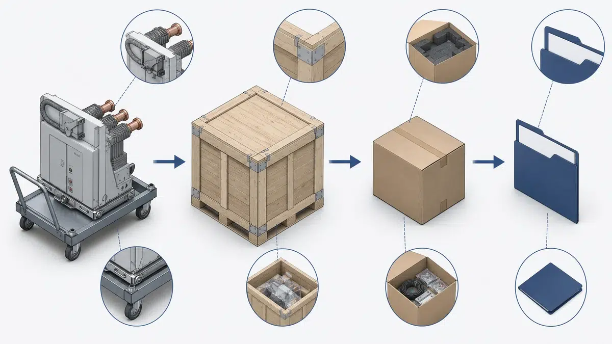
يمكن أن تتضمن RFQ الصياغة التالية:
«على مورد VCB تقديم ورقة بيانات كاملة لدائرة التحكم والتشابك للقاطع المعروض. ويجب أن يحدد التقديم محرر الإغلاق أو ملف الإغلاق، ومحرر الفصل التحويلي أو ملفات الفصل، ومرحل منع الضخ أو وظيفة منع الضخ، ومحرك شحن الزنبرك، والتلامسات المساعدة للآلية، وتلامسات مغناطيس الحجب، والتلامسات المساعدة لتشابك أزرار الضغط، وتلامسات حجب الإغلاق، وتلامسات المفتاح المساعد 52، وتشابكات العربة أو السحب، وأي واجهات تشابك مطلوبة من جانب المفاتيح الكهربائية لتنسيق الفاصل أو مفتاح التأريض. وعلى المورد تقديم المخططات العنصرية ومخططات الأطراف وجدول تلامسات يوضح وظيفة كل تلامس تحكم أو تشابك وموضعه وحالته الطبيعية ووجهة توصيله. كما يجب على المورد تأكيد أن التلامسات المساعدة الخاصة بالقاطع غير موصلة بطريقة تعطل وظيفة منع الضخ المقصودة.» استخدم دليل استكشاف أعطال تشغيل VCB لتمييز أسباب عطل دائرة التحكم أو الملف أو التشابك أو الآلية بعد فشل عملية تشغيل.
تبقى هذه الصياغة ضمن مفاهيم دوائر التحكم الموثقة في VCB، مع إلزام العرض بإظهار التفاصيل المهمة للمراجعة الهندسية.
هي جدول يستكمله المورد لتحديد وظائف الإغلاق والفصل ومنع الضخ والشحن والتلامسات المساعدة والحجب والسحب والتشابك مع المفاتيح الكهربائية في القاطع. وينبغي أن يتضمن مراجع المخططات والأطراف ووظائف التلامسات وحدود النطاق كي يتحقق المشتري من كيفية التحكم في VCB وتشابكه مع المفاتيح الكهربائية.
أهم حقل هو تصريح المورد بكيفية تحقيق منع الضخ وحمايته من التوصيل الخاطئ لدائرة الإغلاق. وتحدد وثائق ABB الخاصة بـVCB مرحلات منع الضخ كجزء من دائرة التحكم، وتحذر إرشادات Schneider من توصيل التلامسات المساعدة الخاصة بالقاطع على التوالي مع محرر الإغلاق وتلامس الإغلاق بطريقة تعطل نظام منع الضخ الميكانيكي.
تشير التلامسات المساعدة للقاطع عموماً إلى حالة آلية القاطع أو تتبعها، مثل المفتاح المساعد 52 أو التلامسات المساعدة للآلية. أما تلامسات التشابك فتستخدم للسماح بعمليات مثل الإغلاق أو الفصل أو تشغيل أزرار الضغط أو السحب أو تشغيل الفاصل أو تنسيق مفتاح التأريض، أو لحجبها أو تنسيقها. وقد تظهر بعض التلامسات في مخطط التحكم نفسه، لكن ينبغي أن تطلب RFQ من المورد بيان الوظيفة الفعلية لكل تلامس.
هو تلامس مستخدم في دائرة الإغلاق أو التشابك لمنع الإغلاق الكهربائي في ظروف محددة. وتصف وثائق ABB SecoVac تلامس حجب الإغلاق إلى جانب ملف الإغلاق ومرحل منع الضخ والمفتاح المساعد 52 وملفات الفصل ومحرك شحن الزنبرك ومكونات الحجب وتشابك العربة الاختيارية. وينبغي أن تطلب RFQ من المورد تحديد التلامس وظروف تشغيله وموضعه في دائرة الإغلاق.
يعني أن الإغلاق الميكانيكي أو الكهربائي لـVCB يمكن منعه بناءً على موضعه أو موضع أجهزة المفاتيح الكهربائية المرتبطة به. وتصف وثائق Siemens تشابكات VCB الكهربائية والميكانيكية، بما فيها تشابك الفاصل أو مفتاح التأريض عبر آليات القفل المغناطيسي ومنع الإغلاق الميكانيكي والكهربائي المعتمد على الموضع. وينبغي أن تطلب RFQ من المورد تحديد المواضع التي تسمح بالإغلاق أو تحجبه.