Hai bisogno delle specifiche complete?
Scarica il nostro Catalogo prodotti 2025 per disegni dettagliati e parametri tecnici di tutti i componenti dei quadri elettrici.
Richiedi il catalogo
Scarica il nostro Catalogo prodotti 2025 per disegni dettagliati e parametri tecnici di tutti i componenti dei quadri elettrici.
Richiedi il catalogo Scarica il nostro Catalogo prodotti 2025 per disegni dettagliati e parametri tecnici di tutti i componenti dei quadri elettrici.
Richiedi il catalogo
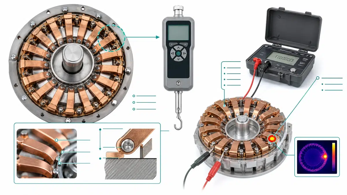
Il surriscaldamento localizzato in un gruppo di contatti a innesto o estraibile è uno dei problemi più comuni e più spesso diagnosticati erroneamente nei quadri elettrici di media e bassa tensione. La termografia evidenzia il sintomo, ma la causa principale è quasi sempre di natura meccanica: la riduzione della forza di serraggio delle molle a livello delle dita di contatto a tulipano. Questa guida illustra l’intero flusso di lavoro relativo alla risoluzione dei problemi e alla manutenzione, dalla diagnosi rapida alla procedura di misurazione, dall’analisi della causa principale alla pianificazione delle ispezioni, dalla lettura delle specifiche all’approvvigionamento dei ricambi.
Prima di procedere con una misurazione completa della forza, usa questa tabella per verificare in quale ramo dei sintomi ti trovi e quale dovrebbe essere il primo test da eseguire.
| Sintomo | Primo test | Probabile causa principale | Azione successiva |
|---|---|---|---|
| La termocamera rileva un punto caldo solo in una o due fasi | Verificare il bilanciamento del carico all'interno del 3%; misurare la forza elastica sulla fase interessata | Forza elastica inferiore al minimo su una o più dita | Effettuare una misurazione completa della forza esercitata da ciascun dito; sostituire se il valore è inferiore alla soglia |
| Scolorimento o bluastro dovuto al calore sulle dita a contatto | Ispezione visiva e misuratore di forza delle molle | Un precedente evento termico ha provocato la ricottura; la deformazione elastica è progredita | Controllo della forza e misurazione della resistenza di contatto (microohm); considerare entrambi |
| Riscaldamento uniforme in tutte le fasi nella stessa posizione | Verificare la corrente di carico e il contenuto armonico | Sovraccarico del sistema o distorsione armonica, non guasto della molla | Escludere cause legate al carico prima di dichiarare difettosi i contatti |
| Punti critici ricorrenti dopo la pulizia a contatto | Misurazione della forza della molla dopo ogni ciclo di manutenzione | Affaticamento primaverile dovuto a precedenti cicli di surriscaldamento | Se la forza non torna alla normalità dopo la pulizia, sostituire il set di dita |
| Difficoltà nell'inserimento o nell'estrazione dell'unità rimovibile | Misuratore di forza rispetto al limite massimo di forza specificato dal produttore originale (OEM) | Una forza eccessiva della molla causa usura da sfregamento e rigature sul perno | Verificare il rispetto del limite massimo; controllare l'eventuale usura del rubinetto |
| Nessun sintomo visibile, ma l'impianto ha più di 15 anni | Verifica programmata della forza elastica | Rilassamento da sollecitazione e fatica legati all'età | Considerarlo come misura preventiva; non affidarsi esclusivamente alla termografia |
| Picchi di temperatura al carico massimo, valore di riferimento a carico ridotto | Misurazione della profondità di inserimento con calibro di profondità | Profondità di inserimento insufficiente; area di contatto effettiva ridotta sotto carico | Correggere la geometria del meccanismo di inserimento; ricontrollare la profondità rispetto al disegno dell'OEM |
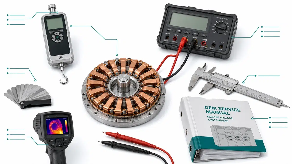
| Strumento | Scopo | Fonte di accettazione | Specifiche minime |
|---|---|---|---|
| Misuratore di forza a molla calibrato (misuratore di trazione) | Misura della forza radiale per dito | Manuale di manutenzione OEM; serie IEC 62271 | Intervallo 0-50 N; risoluzione +/- 0,1 N; corrente di calibrazione |
| Tester di resistenza di contatto in microohm | Verificare la resistenza all'interfaccia di contatto | Manuale OEM; IEEE C37.09 | Risoluzione: 1 microohm; corrente di prova >= 100 A CC |
| Calibri a corsoio | Misurare il diametro interno del tulipano e la geometria delle alette | Disegno quotato OEM | Risoluzione 0,02 mm |
| Set di spessimetri | Controllo supplementare dell'innesto delle dita | Procedura OEM | Intervallo 0,05-0,5 mm |
| Termocamera a infrarossi | Individuare i gruppi di componenti da sottoporre ad analisi delle forze | Linee guida sulla termografia secondo la norma IEC TR 62368 | Sensibilità <= 0,1 °C; risoluzione minima 320 x 240 |
| Tester di resistenza di isolamento | Verificare l'integrità del dielettrico dopo gli interventi di manutenzione | Manuale OEM; IEC 60060 | Uscita da 5 kV per apparecchiature a media tensione |
| Profondimetro | Verificare la profondità di inserimento del plug-in | Tolleranza del disegno di assemblaggio OEM | Risoluzione 0,1 mm |
| Certificati di taratura | Verificare la tracciabilità degli strumenti | Laboratorio accreditato secondo la norma ISO/IEC 17025 | Corrente entro 12 mesi |
| Manuale di manutenzione OEM | Soglie di forza, criteri di accettazione, valori di coppia | Produttore di componenti originali | Revisione specifica per l'attrezzatura |
| Specifiche di progetto o standard di manutenzione | Soglie di accettabilità del sito | Standard dell'ingegnere responsabile o standard dell'azienda di servizi pubblici | Documento specifico per il sito |
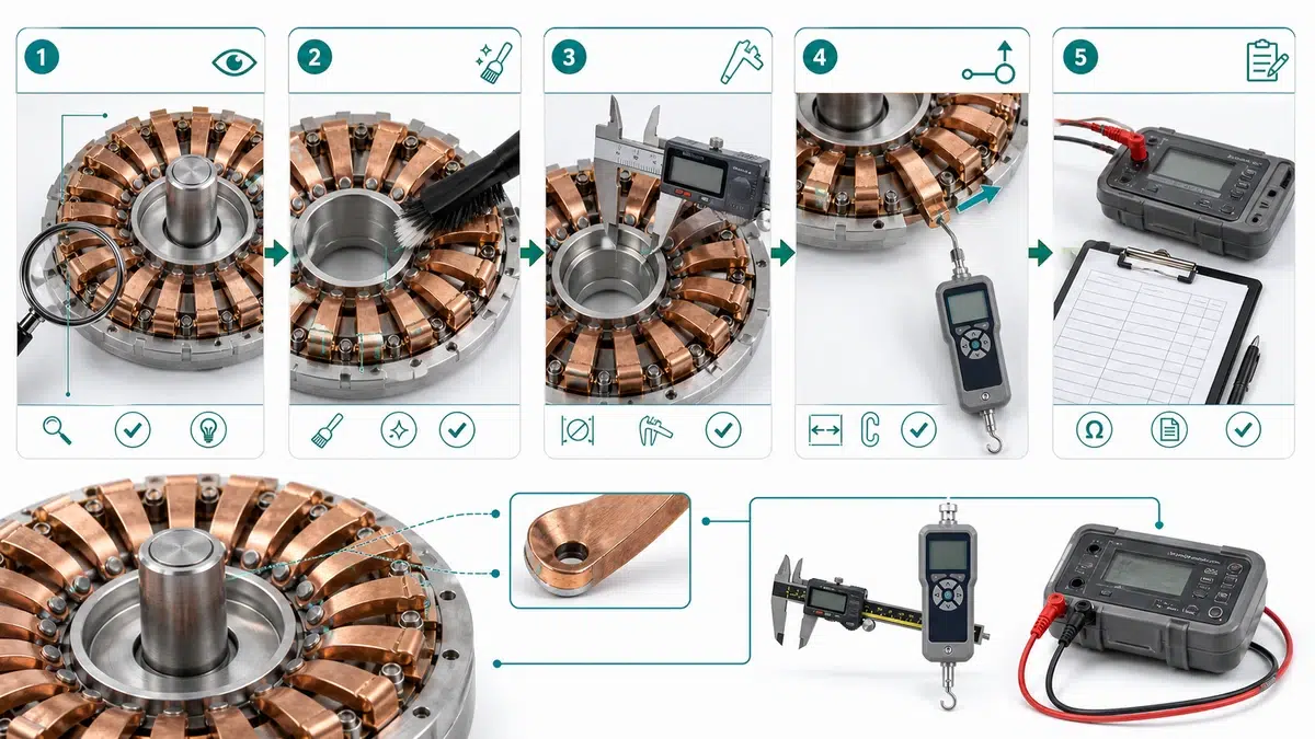
La termografia a infrarossi rileva una traccia termica solo dopo che la resistenza di contatto ha già raggiunto un livello dannoso. La verifica della forza delle molle di contatto Tulip è un indicatore anticipatore: individua una ridotta capacità di serraggio prima che le conseguenze termiche diventino visibili o prima che l’isolamento e i componenti adiacenti subiscano danni termici cumulativi.
Prima di entrare in contatto con qualsiasi componente, è necessario completare e verificare la disalimentazione e l'isolamento tramite la procedura di lockout/tagout del sito. Verificare che il meccanismo di interblocco sia innestato e che l'energia accumulata nei meccanismi a molla sia stata scaricata.
Fase 1 – Controllo visivo preliminare
Fase 2 – Pulizia delle superfici di contatto
| Parametro | Pass | Monitor | Rifiuto |
|---|---|---|---|
| Forza esercitata da ogni singolo dito | >= valore nominale per dito (in genere 8-12 N) | 70-99% del valore nominale | < 70% del valore nominale |
| Forza di contatto complessiva | >= 100% della forza di montaggio nominale | 80-99% della forza di assemblaggio nominale | < 80% della forza di montaggio nominale |
| Dita non valide (al di sotto della soglia) | 0 | 1 dito (da sostituire al prossimo blackout) | >= 2 dita |
| Spessimetro con lama da 0,2 mm | Rifiutato da tutte le dita | 1 dito si inserisce nella lama | >= 2 dita possono afferrare la lama |
| Scostamento del diametro del foro | <= +0,1 mm rispetto al valore nominale | da +0,1 a +0,3 mm | > +0,3 mm |
| Condizioni visive | Nessuno scolorimento, nessuna deformazione | Solo una leggera ossidazione superficiale | Bluaggio da calore, crepe, corrosione puntiforme o dita mancanti |
Il surriscaldamento localizzato in un gruppo di contatto a tulipano raramente ha un'unica causa, ma la riduzione della forza elastica è sempre uno dei primi fattori da escludere o confermare.
| Forza elastica misurata rispetto al valore minimo OEM | Livello di rischio termico | Azione raccomandata |
|---|---|---|
| >= 100% come specifica minima | Basso | Nessuna azione immediata; registrare per valutare l'andamento |
| 90-99% con specifiche minime | Moderato | Aumentare la frequenza delle ispezioni; pianificare la sostituzione |
| 75-89% con specifiche minime | Alto | Sostituire in occasione della prossima interruzione programmata; se possibile, ridurre il carico |
| < 75% rispetto alle specifiche minime | Critico | Sostituire prima di rimettere in funzione |
Sintomo: La scansione a infrarossi mostra un differenziale di temperatura di 22 °C sul grappolo di tulipani della fase B rispetto alle fasi A e C. Il bilanciamento del carico è confermato all'interno del 3% in tutte le fasi.
Misura: La misurazione della forza per singolo dito effettuata sul gruppo della fase B ha rilevato che undici dei sedici dita erano al di sotto del valore minimo specificato dal produttore originale. Il valore nominale era di 18 N per dito; l'intervallo misurato era compreso tra 9 e 13 N sulle dita interessate. Sono state osservate deformazioni visibili e una lunghezza libera ridotta rispetto ai pezzi di ricambio non utilizzati dello stesso lotto di produzione.
| Meccanismo di degradazione | Causa principale | Effetto misurabile | Condizione di accelerazione | Azione correttiva |
|---|---|---|---|---|
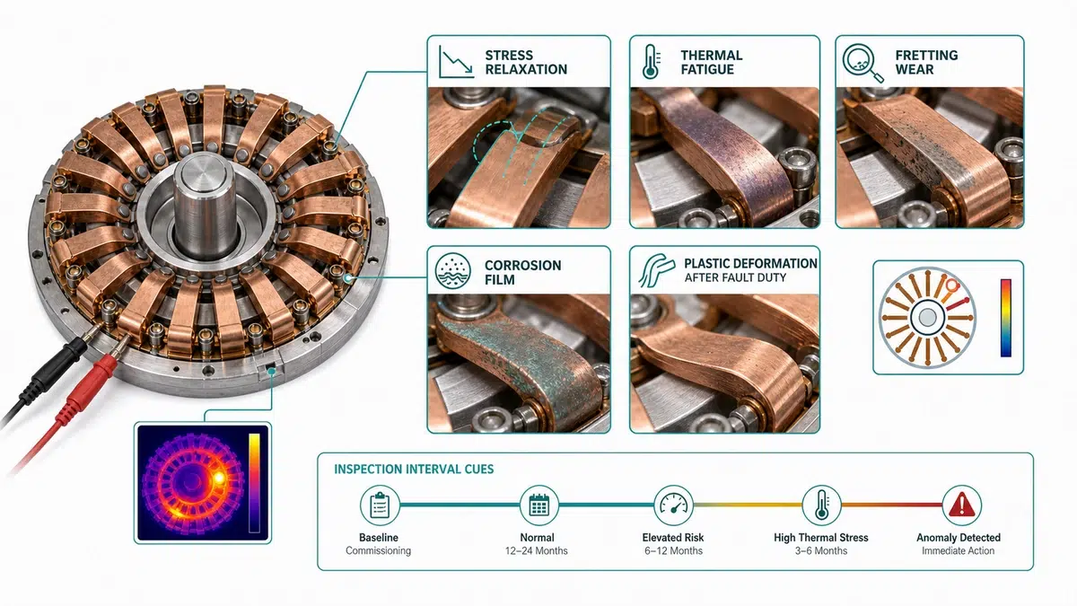
| Rilassamento da sollecitazione (scorrimento) | Il carico statico prolungato supera il limite elastico nel corso del tempo | Riduzione progressiva della forza senza deformazioni visibili | Temperatura ambiente elevata, lama sovradimensionata, permanenza prolungata in posizione chiusa | Sostituire il set di molle; verificare la tolleranza dimensionale della lama |
| Affaticamento termico | I ripetuti cicli termici provocano la formazione di microfessure alla base della molla | Forza irregolare tra gli stati termici; la forza misurata a caldo è inferiore rispetto a quella misurata a freddo | Elevata frequenza giornaliera di commutazione, sovraccarico continuo, scarsa ventilazione | Sostituire il set di molle; verificare l'equilibrio di corrente tra le fasi |
| Deformazione plastica (sovraccarico) | Un singolo evento di sovraccarico o un inserimento eccessivo di natura meccanica blocca definitivamente la molla | Dita visibilmente divaricate o piegate; forza permanentemente ridotta | Eventi di corrente a livello di guasto, racking con bus disallineato, geometria delle pale non conforme a quella dell'OEM | Sostituire il set di molle; verificare i dati relativi ai guasti a monte |
| Corrosione e film superficiale | L'ossidazione o la solforazione aumentano la resistenza superficiale senza alterare la forza meccanica | Riscaldamento sproporzionato rispetto alla lettura della forza; resistenza di contatto elevata | Elevata umidità, ambiente costiero o industriale, funzionamento sporadico | Pulire le superfici; ricontrollare la forza e la resistenza; sostituire se si riscontrano problemi strutturali |
| Infragilimento del materiale a molla | Infragilimento da idrogeno o invecchiamento in leghe di rame sottoposte a sollecitazioni elevate | Improvvisa perdita di forza o rottura della molla; variazione brusca anziché graduale | Età superiore alla durata di servizio, atmosfera ricca di idrogeno, residui di placcatura | Sostituire il set di molle; contrassegnare il lotto per l'ispezione della flotta |
| Usura da sfregamento (perdita del precarico) | I micromovimenti tra la sede della molla e l'alloggiamento causano la perdita di materiale | Forza ridotta; presenza di residui di usura visibili alla base della molla | Ambiente soggetto a forti vibrazioni, fissaggio allentato dell'alloggiamento | Controllare la geometria della seduta; sostituire il gruppo molle e l'alloggiamento se la profondità della seduta non rientra nei limiti di tolleranza |
| Rimontaggio errato | Molla installata con orientamento errato, in quantità errata o senza gli strumenti adeguati | Forza al di fuori delle specifiche immediatamente dopo la manutenzione | Messa in servizio post-manutenzione senza verifica della forza | Rimontare utilizzando gli utensili OEM; eseguire la verifica della forza prima dell'alimentazione |
| Condizioni del campo | Intervallo di riferimento (anni) | Intervallo rettificato | Meccanismo di rischio primario |
|---|---|---|---|
| Sottostazione interna pulita, umidità controllata (< 60% RH), commutazioni minime | 6 | 6 | Solo rilassamento elastico di base |
| Ambiente costiero o ad elevata umidità (> 80% RH, aria salina) | 6 | 2-3 | La corrosione accelera l'ammorbidimento delle dita |
| Ambiente industriale in presenza di polveri conduttive o vapori chimici | 6 | 2 | La contaminazione aumenta il carico di attrito; la forza della molla diminuisce più rapidamente |
| Elevata frequenza di commutazione (> 200 operazioni all'anno) | 6 | 2-3 | Affaticamento meccanico dovuto a ripetuti inserimenti ed estrazioni |
| Evento successivo a un guasto (di qualsiasi entità superiore alla resistenza nominale) | Immediato | Immediato | Le forze elettromagnetiche possono deformare in modo permanente le linguette elastiche |
| Installazione soggetta a vibrazioni (in prossimità di macchinari pesanti, in zona sismica) | 6 | 3 | L'usura da sfregamento provoca un progressivo deterioramento del contatto |
| Mancanza di registrazioni relative alla manutenzione o storia di manutenzione sconosciuta | Sconosciuto | Immediato | La verifica stabilisce un valore di riferimento noto prima di proseguire il funzionamento |
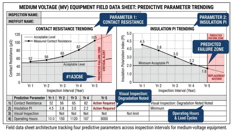
Se la forza misurata diminuisce di oltre 5% per ciclo di ispezione, ridurre l’intervallo successivo di 30-40% anziché attendere il superamento della soglia di guasto. La verifica della forza delle molle è inoltre obbligatoria al momento della messa in servizio iniziale e dopo qualsiasi intervento di manutenzione interna in cui le dita vengano rimosse, pulite o lubrificate.
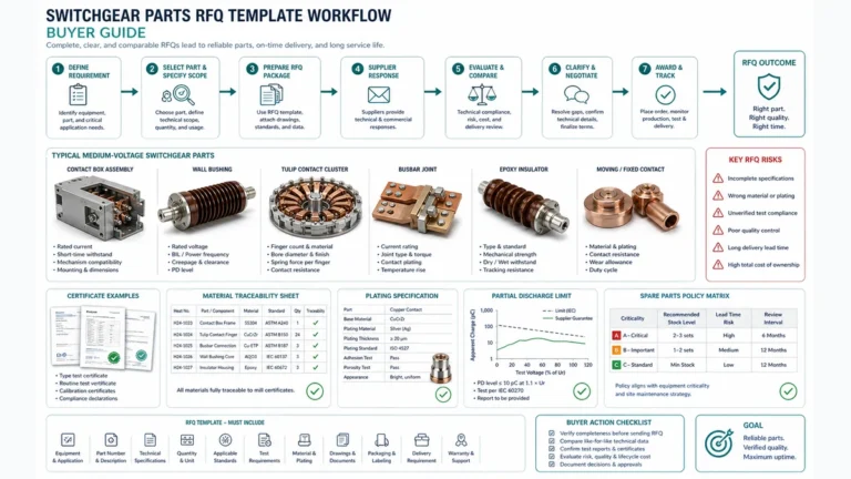
Per ordinare un gruppo molla di contatto a tulipano di ricambio basandosi esclusivamente sul numero di modello del quadro elettrico, raramente è sufficiente. I produttori modificano la geometria delle molle, il numero di dita e le specifiche di precarico nel corso dei diversi cicli di produzione.
| Articolo mancante | Esito probabile |
|---|---|
| Non è specificata alcuna tolleranza di forza | Il fornitore effettua le spedizioni in base ai valori nominali indicati nel catalogo; la forza effettiva potrebbe attestarsi al limite di tolleranza |
| Non è stato confermato il numero di dita | Assemblaggio installato con un numero errato di dita; ricalcolo della forza per dito saltato |
| Non è specificato alcun rivestimento | La placcatura sostitutiva produce un valore di riferimento diverso per la resistenza di contatto |
| Non sono stati forniti dati relativi al riscaldamento | La causa principale non è stata confermata; la sostituzione potrebbe non risolvere l'anomalia termica |
| Non è richiesto alcun certificato di collaudo | Non è possibile verificare la conformità delle forze prima dell'installazione |
Identificazione delle attrezzature
– Codice articolo OEM comprensivo del suffisso di revisione
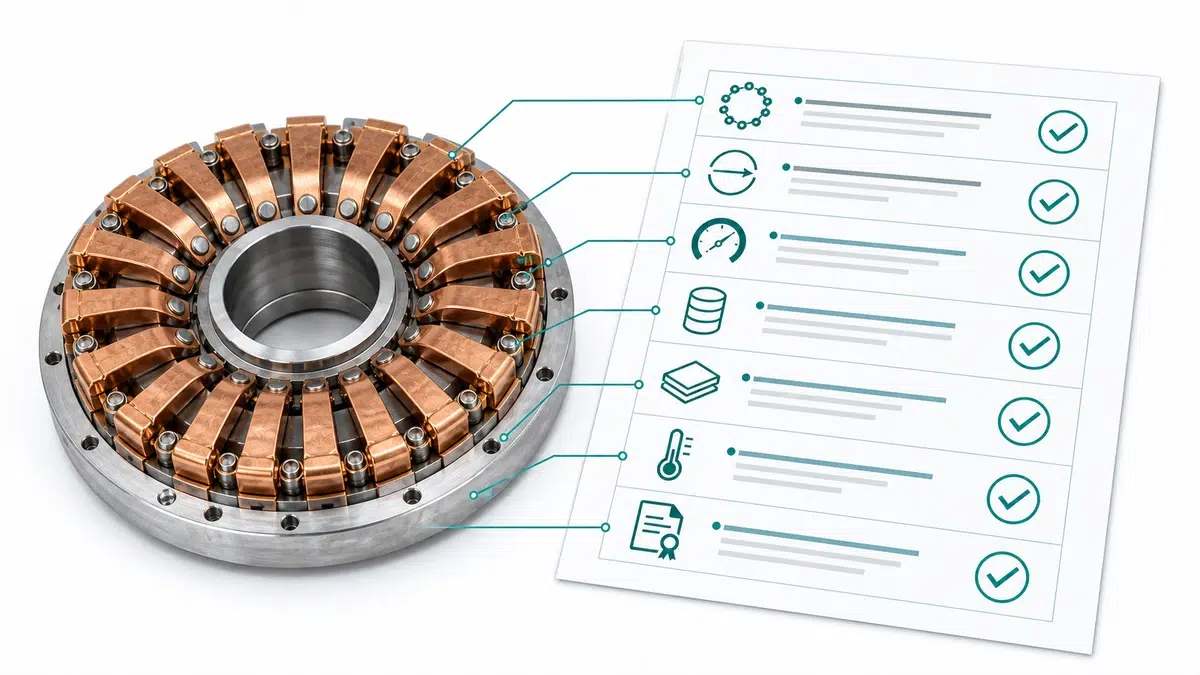
Utilizzate questi riferimenti XBRELE per collegare la decisione sul campo al corretto flusso di lavoro relativo al prodotto, ai test e all'approvvigionamento: Pagina del prodotto XBRELE, Gamma di interruttori in vuoto XBRELE, Guida ai rating VCB, Lista di controllo per l'accettazione del VCB FAT/SAT, gamma di componenti per quadri elettrici XBRELE.
Per il contesto del metodo esterno, confrontare la procedura del sito con il metodo pubblico Pagina degli standard IEEE C37.09 e quindi applicare l'esatto manuale OEM e le specifiche di progetto per l'apparecchiatura fornita.
Esempio sul campo: durante un'ispezione di servizio, una fase ha misurato al di fuori della sua linea di base di messa in servizio, mentre le altre due fasi sono rimaste stabili. Il team ha ripetuto la misura con conduttori verificati, ha controllato la tempistica e la corsa dei contatti e ha utilizzato la divergenza misurata per separare un problema di pressione dei contatti da un generico problema di pulizia delle superfici.
La forza minima accettabile è definita dal produttore OEM per ogni specifico gruppo ed è espressa per singolo polo (di solito 8-18 N a seconda della corrente nominale e della geometria dei contatti) e come valore complessivo per l'intero gruppo. Non esiste un valore minimo universale valido per tutti i modelli.
Per le installazioni interne pulite con un numero minimo di commutazioni, si applica un intervallo di riferimento di 6 anni. Tale intervallo si riduce a 2-3 anni in ambienti costieri, ad alta umidità o sottoposti a carico elevato, nonché in caso di verifica immediata a seguito di qualsiasi evento di guasto in linea, dopo qualsiasi intervento di manutenzione interna sul gruppo di contatto e al momento della messa in servizio iniziale.
Sì. Un singolo dito che non esercita alcuna forza di serraggio utile concentra la corrente attraverso i dita adiacenti, aumentando la densità di corrente locale e il riscaldamento dovuto alla legge I²R in quei punti di contatto.
No. La sostituzione di singole dita all’interno di un gruppo esistente comporta una discrepanza tra le rigidità elastiche delle dita nuove e di quelle usurate, con conseguente ridistribuzione non uniforme della pressione di contatto.
Il rilassamento da sollecitazione è una riduzione graduale e dipendente dal tempo della forza di serraggio a deformazione costante: la molla mantiene la propria forma ma esercita una forza progressivamente minore nel corso di mesi o anni, in particolare a temperature elevate. La deformazione plastica è una variazione immediata e permanente della geometria della molla causata da un singolo evento di sovraccarico, come una corrente di guasto o un inserimento meccanico eccessivo, e produce una curvatura o un allargamento visibile del dito.
Una profondità di inserimento insufficiente sposta la pressione di contatto verso le punte delle dita anziché verso la zona di contatto centrale prevista dal progetto, riducendo l’area di contatto effettiva anche se ogni dito genera la propria forza di serraggio nominale. Ciò produce un surriscaldamento indistinguibile dal degrado della forza elastica in una scansione termica; ecco perché, durante ogni analisi dei contatti, è necessario verificare la profondità di inserimento indipendentemente dalla forza elastica.
La norma IEC 62271-100 definisce i requisiti prestazionali per gli interruttori automatici in corrente alternata, comprese le specifiche relative ai contatti, mentre la norma IEC 62271-200 riguarda i quadri di comando e controllo in involucro metallico. Per le applicazioni nordamericane si applicano le norme della serie ANSI/IEEE C37.