Нужны полные технические характеристики?
Загрузите наш каталог продукции 2025 года, чтобы ознакомиться с подробными чертежами и техническими параметрами всех компонентов распределительного устройства.
Получить каталог
Загрузите наш каталог продукции 2025 года, чтобы ознакомиться с подробными чертежами и техническими параметрами всех компонентов распределительного устройства.
Получить каталог Загрузите наш каталог продукции 2025 года, чтобы ознакомиться с подробными чертежами и техническими параметрами всех компонентов распределительного устройства.
Получить каталог
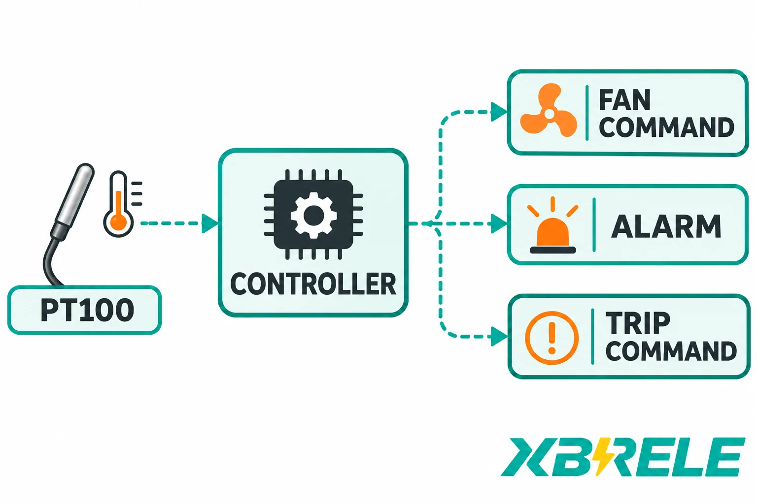
Understand dry-type transformer Pt100 sensing, fan hysteresis, alarm, trip and sensor-fault logic, plus the interface checks needed for a project specification.
A dry-type transformer temperature controller does not cool the transformer and it does not disconnect it. It measures the resistance of platinum sensors embedded in the windings, converts that resistance into a temperature per channel, compares the results against a small set of project-defined settings, and operates dry contacts. Those contacts then command something else — a fan contactor coil, an annunciator, a SCADA input, or a breaker shunt-trip circuit through whatever interposing relays the panel designer installed.
That separation is what makes the device specifiable. The sensor belongs to the transformer, the controller belongs to the panel, the dry contact is a signal, the auxiliary supply is a separate circuit, and the actual interrupting device is a breaker or contactor with its own rating and its own control chain. Every confusing requirement in a temperature-monitor specification can usually be traced to one of these five responsibilities being assigned to the wrong component.
This article follows that chain in order: what the Pt100 channel measures, how cooling decisions differ from alarm and trip decisions, how fault states must be kept distinct from hot states, and which interfaces a project has to define before a controller can be ordered.
The chain has five links.
Measurement. One or more Pt100 elements sit at defined positions in the winding or in the cast-resin body. Their resistance changes with temperature. The controller’s input circuit excites the element, reads the resulting voltage, and linearises it into a temperature value for that channel.
Decision. Firmware compares each valid channel against settings: a fan-on value, a fan-off value, an alarm value, a trip value, and usually a set of time delays and channel-selection rules. The comparison result is a state — normal, cooling required, alarm, trip, or channel invalid.
Output. State changes operate relay contacts. These are dry relay contacts whose permitted AC/DC and resistive/inductive duties must be checked. A pilot output commands a correctly rated downstream device; it does not interrupt the transformer primary circuit.
Transfer. Wiring between the controller terminals and the panel carries those contact states to their destinations: a contactor coil, an interposing relay, a breaker shunt-trip coil, a lamp, a horn, a PLC input, a remote terminal unit.
Action. The downstream device does the physical work. A contactor starts a fan motor from a motor supply with its own short-circuit and overload protection. A shunt-trip coil releases a breaker that has its own interrupting rating.
The important consequence: a controller “trip output” is a command, not an interruption. If the trip contact is wired to nothing, or wired to a coil whose supply is dead, or wired through an interposing relay that has failed, the transformer keeps running at elevated temperature and every indication in the control room says the protection worked. The signal path has to be verified end to end, which is a different activity from verifying the controller.
A Pt100 is a platinum resistance thermometer with a nominal resistance of 100 Ω at 0 °C. Platinum was chosen because its resistance-temperature relationship is stable and repeatable over long periods, and 100 Ω is a convenient compromise: high enough that lead resistance is not overwhelming, low enough that self-heating from the excitation current stays small.
Over the range a transformer sees, the relationship is close to linear with a positive slope: roughly 0.385 Ω per °C near 0 °C for the common 0.00385 characteristic, so a winding at 100 °C reads around 138.5 Ω rather than 100 Ω. The controller does not display resistance; it inverts this relationship in firmware and presents a temperature. That inversion is only as good as the input circuit’s assumption about the element, which is why a Pt100 channel and a PTC channel are not interchangeable inputs.
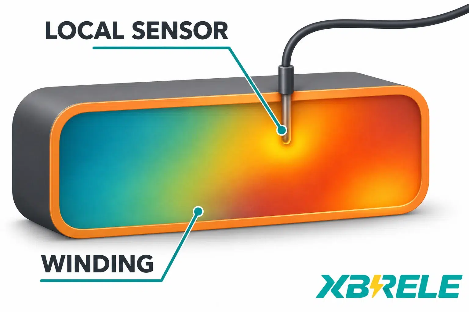
Local measurement is not a hot-spot measurement. A sensor embedded at a specific point in a winding reports the temperature at that point. The winding has a thermal field: the conductor’s hottest point is typically somewhere inside the coil, influenced by duct geometry, layer arrangement, load current distribution and the cooling path. One embedded probe is a well-placed witness, not a survey of the whole winding. Practical consequences:
Lead resistance and wire count. A Pt100’s signal is a resistance change of tenths of an ohm per degree, so the resistance of the connecting cable matters. A two-wire connection adds the loop resistance of both leads directly to the measurement; with the usual copper extension cable, a fraction of an ohm of loop resistance translates into more than a degree of error, and the error moves with cable temperature. A three-wire connection measures the lead loop and compensates, on the assumption that the leads are matched; unequal leads leave a residual offset. A four-wire connection separates the excitation current from the sensing pair and removes lead resistance almost entirely. Transformer sensors are commonly supplied with three-wire shielded extension, as illustrated by the TECSYSTEM PTSW sensor. Whatever the wiring, the controller input must be configured for the wire count actually installed — a mismatch may cause an offset, an invalid reading or a diagnostic fault, depending on the input design.
Pt100 is not PTC. A PTC thermistor used for transformer or motor protection is a threshold device: its resistance stays low until the element reaches a nominal response temperature, then rises steeply. It answers “has this point passed its reference temperature?” and returns a step, not a reading. A Pt100 answers “what is the temperature here?” and returns a value. Protection schemes built on PTC elements trip on the step; schemes built on Pt100 elements compare values against settings. Mixing the two at one input is a common commissioning error and produces either a permanent fault indication or a plausible but meaningless number.
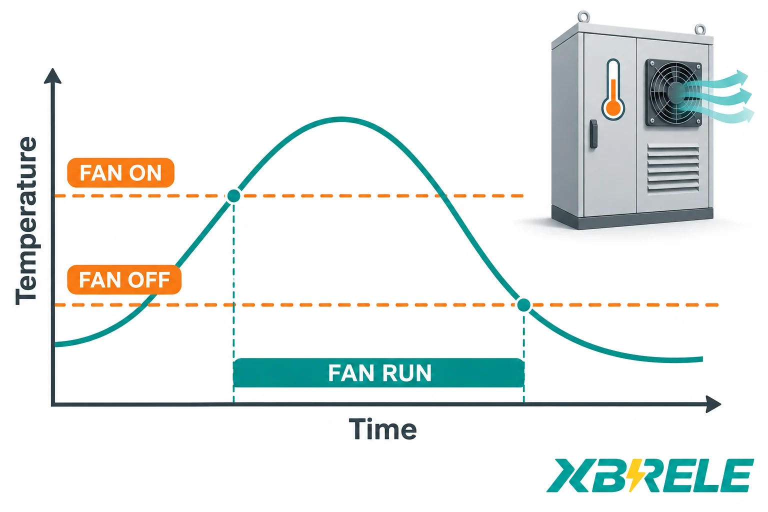
Cooling is a separate control function from protection, and it needs its own settings.
Why fan ON and fan OFF differ. If a fan started and stopped at one temperature, any load condition holding the winding near that value would produce continuous cycling — contactor chatter, motor starting current every few minutes, and unnecessary wear. Two settings create a band: the fan starts when temperature rises through the fan-on value and stops only after temperature has fallen through the lower fan-off value. The gap plus the controller’s delay settings keeps the cooling decision stable. The TECSYSTEM T154 manual, in its fan-control and temperature-diagnostics sections, describes separate fan ON/OFF and alarm/trip settings, plus an optional periodic fan command. That architecture — separate fan band, separate alarm, separate trip — is the normal pattern across this class of controller. Its numeric values are device-specific and should not be copied between projects.
Hysteresis is not a substitute for alarm timing. A fan band prevents cycling. Alarm and trip delays serve a different purpose: they ride through short excursions and prevent a transient from producing a trip command. They are tuned independently, and an alarm delay long enough to suppress nuisance events is not automatically appropriate for the trip path.
Command is not airflow. A fan command contact closing proves that the controller decided to cool. It does not prove that the contactor pulled in, that the motor turned, that the impeller is intact, or that air is moving through the winding ducts. Without a return signal, the control room sees “cooling on” for a transformer that is not being cooled. Proving methods differ by installation: an auxiliary contact confirms the contactor mechanism/auxiliary-contact state, not the complete coil circuit or the motor; a current relay indicates motor-circuit current, while an overload auxiliary reports the protection device state; an airflow switch confirms air movement but adds a device that can itself fail. Each proves a different segment, and the specification should say which segment matters for the project.
The fan circuit is a motor circuit. The controller’s output is a pilot signal. The contactor coil voltage and burden must match what the output can switch; the motor supply, short-circuit protection and overload protection must match the actual fan motor nameplate. A controller contact rated for a small pilot load will not carry motor current, and a motor circuit without overload protection is a fire risk that no temperature controller detects.
Coil fans and room fans solve different problems. Fans mounted to blow air through the winding’s internal ducts raise the convective heat transfer from the conductor surfaces and are the basis of a forced-cooling rating. Room extraction can remove heat from the room when an adequate cooler replacement-air path exists. An enclosure fan may exchange enclosure air with the room without removing room heat. They respond to different measurements — a winding channel for coil fans, often an ambient channel for room ventilation — and they fail in different ways. Treating them as one “fan output” hides which cooling path is being commanded.
A fan retrofit does not create a rating. For dry-type transformers, natural and forced cooling correspond to different declared capacities, because forced air changes the heat transfer coefficient and the winding temperature rise at a given load. The higher figure is a property of the transformer’s thermal design, established by the manufacturer’s design analysis and test evidence, not a property of the fan or the controller. A controller that switches a fan on at a setpoint is compatible with a forced-cooling design; it does not confer one, and the capacity at each cooling mode must be requested as project data with the transformer, not assumed from the presence of a fan.
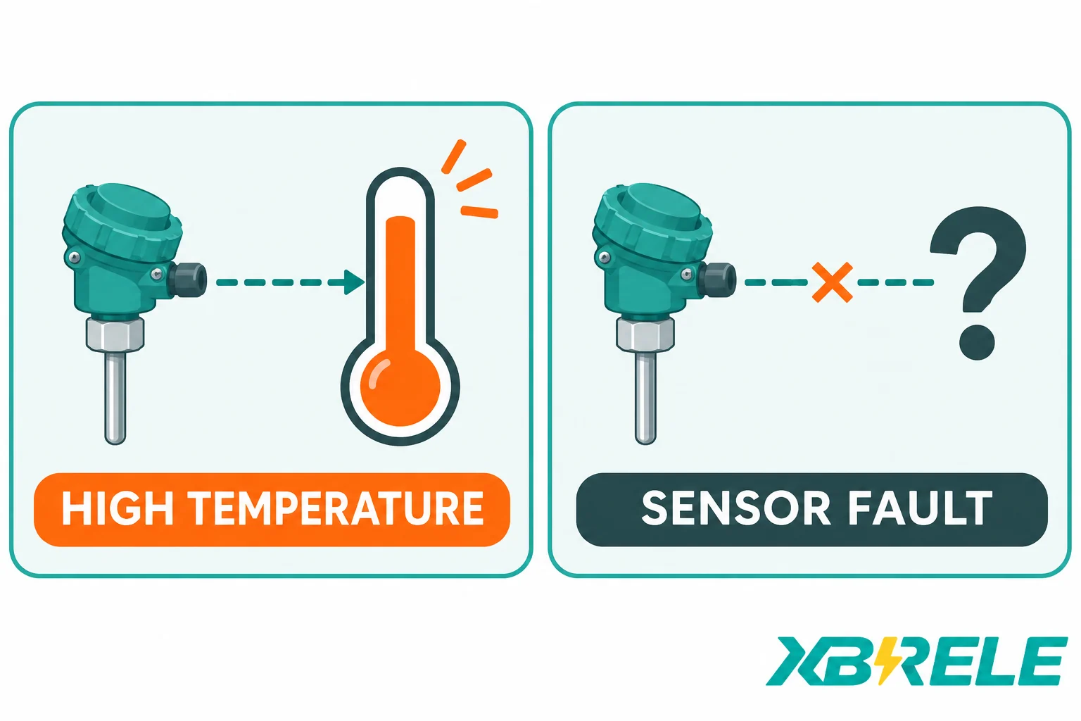
The most consequential specification decision in this whole subject is whether a lost measurement counts as an overheating event. They are not the same thing, and a panel that treats them as one produces a system nobody can diagnose.
A sensor that opens, a sensor that shorts, a cable that is crushed, a terminal that corrodes, a controller input that fails — all of these produce a state in which the temperature is unknown. None of them proves the winding is hot. A genuine thermal event can affect one phase or location as well as several. Judge channel validity, loading and cooling evidence together; agreement between channels is not a prerequisite for a real hot condition.
| Состояние | Measurement status | Typical outputs | What the project should do |
|---|---|---|---|
| Нормальный | All enabled channels valid, below the cooling threshold | Fan off; alarm and trip contacts in their normal state | Nothing beyond trending |
| Cooling stage | Valid; the evaluated channel is above the fan-on value | Fan command operated; alarm and trip unchanged | Verify the cooling path is actually delivering air |
| High temperature | Valid; above the alarm threshold | Alarm contact operated; fan still commanded | Investigate load, blocked ducts, ambient, fan failure |
| Trip level | Valid; above the trip threshold | Trip contact operated; latching may be in the controller or downstream scheme | Open the breaker through the approved chain, then investigate before reset |
| Sensor open circuit | Invalid; the channel is reported as faulty, not as a high reading | Fault or alarm output; whether the trip asserts depends entirely on policy | Restore the measurement; do not read the state as temperature |
| Sensor short circuit | Invalid; reported as faulty | Fault or alarm output | Same, plus inspect for moisture or cable damage |
| Controller power loss | No measurement at all | Conventional non-latching relays return to their de-energised state; verify the actual design | Depends on relay wiring: either an alarm for loss of a healthy signal, or silence |
Read the last row carefully. In an energise-to-trip shunt-trip scheme, loss of the controller supply does not by itself energise the trip coil. Monitoring one normally-closed contact alone does not supervise the complete trip wire, coil and supply. A de-energise-to-trip scheme instead uses loss of an energised healthy loop to operate a suitable downstream arrangement, such as an approved undervoltage or interposing scheme. A broken wire produces the intended protective action only if the complete loop and final actuator were designed that way and the required operating energy remains available. Merely selecting an NC controller contact does not establish this behaviour.
The policy for sensor failure also remains distinct from the output convention. The T154 manual specifically warns against connecting its FAULT relay directly to the transformer trip circuit. Follow the selected controller’s instructions and coordinate any required loss-of-monitoring response through the approved protection design.
Two distinctions support that decision:
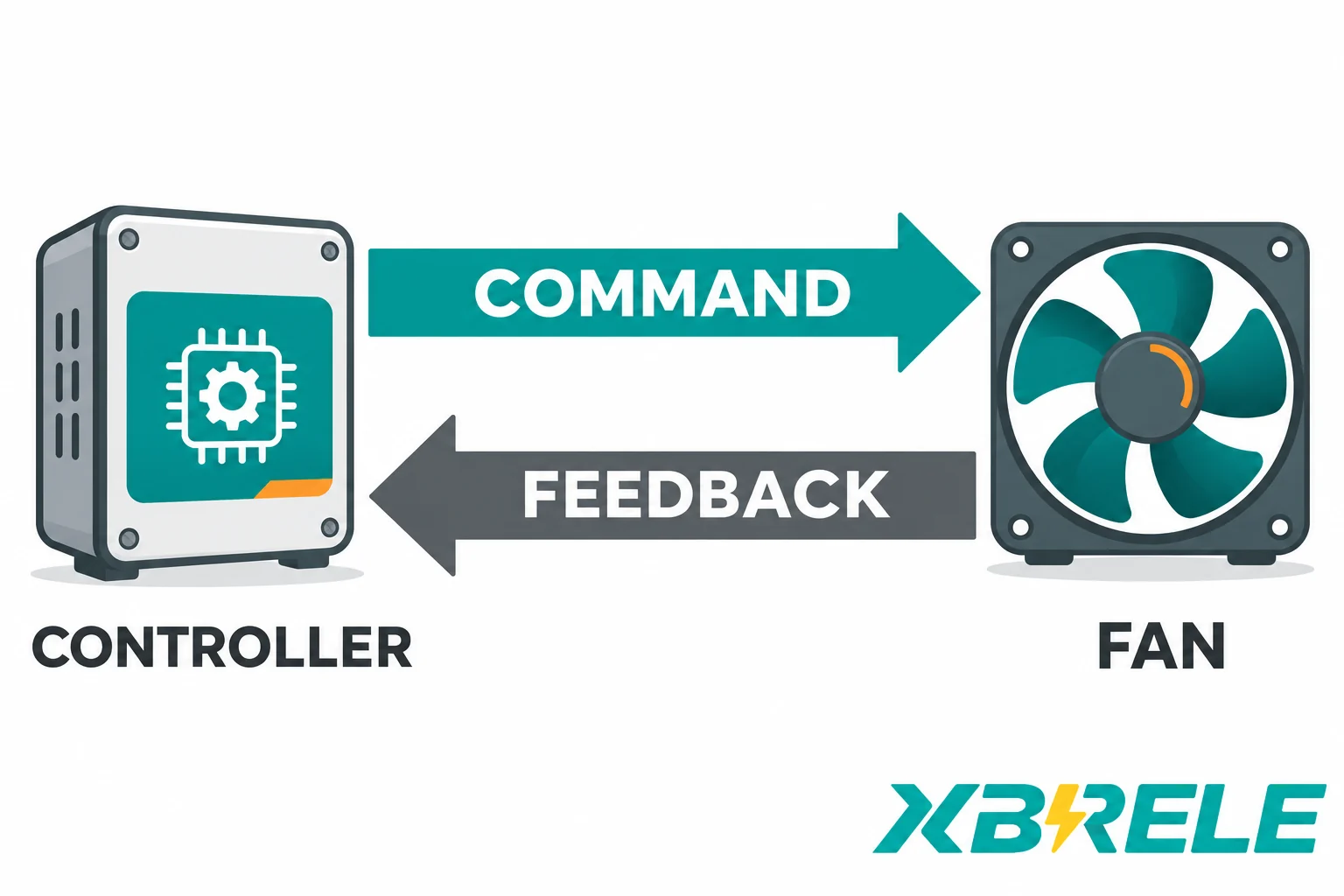
Most procurement failures here are interface failures, not controller failures. The following items define the boundary and should appear in the specification as explicit project statements.
Dry contact duty. For each output — fan, alarm, trip, and any fault or self-test output — state the intended load: coil voltage and type, whether it is AC or DC, whether the load is resistive or inductive, the current, and the interposing arrangement. Contact ratings are given for specific load categories, and a rating quoted for one category does not transfer to another. If a breaker shunt-trip coil draws a short-duration current beyond the controller’s contact rating, the project needs an interposing relay, and the contact then only switches that relay’s coil.
Auxiliary supply. Voltage, tolerance, frequency or DC polarity, burden, and whether the supply is backed up. The controller’s supply is a separate circuit from the measurement wiring and from the motor supply; a common mistake is to take it from a source that disappears exactly when the switchroom is in trouble.
Input count and channel assignment. How many winding channels, whether an ambient channel is fitted, and which physical sensor connects to which numbered input. The mapping must match the drawing and the commissioning record, because “channel 2” means nothing at the plant without a documented correspondence to a phase and a position.
Channel evaluation logic. Which channels participate in the fan, alarm and trip decisions; how a channel already flagged as faulty is excluded; whether the logic uses the maximum valid value, an average, or a voting rule. If two of three phase channels are faulty, the remaining channel does not restore coverage of the other phases. Specify the degraded-coverage indication and approved operating response.
Latching and reset. Define whether the controller output, a downstream lockout or neither is latched, and whether deliberate reset is required after a trip. An alarm may self-reset according to its configured clearing rule. Define the reset source — local pushbutton, remote digital input, SCADA command — and define whether reset can be performed while the initiating condition persists. Auto-resetting a trip level condition allows the plant to re-close into the same fault repeatedly, which is rarely intended.
Signal fault and power-loss policy. Whether an invalid channel raises an alarm only, or also inhibits cooling logic, or asserts trip. This is the row from the matrix that most needs a written decision, and it usually differs between an attended and an unattended installation.
Fan feedback. Whether a return signal exists, what it proves (contactor, motor current, or airflow), which input it lands on, and what the controller or panel does when the command is present without the proof. Without this, the diagnostic difference between a failed fan and a failed channel disappears.
Isolation, EMC and shielding. Sensor cables run from inside a transformer to a panel in the same room, alongside contactor and busbar wiring. Shielded cable with the shield bonded according to the manufacturer’s instructions, physical separation from power wiring, and the controller’s own isolation between measurement, supply and relay circuits are all installation requirements that come from the device documentation. They are not optional refinements; they determine whether the channel reads a winding or a switching transient.
SCADA mapping separate from the trip path. Analogue or bus-based temperature values, states and alarms going to a supervisory system are useful for trending and for diagnostics. They are not the trip path. Where the project specifies a hardwired trip, maintain its defined independence from the supervisory link, and specify the SCADA point list separately so a change in the supervisory system cannot alter protection behaviour.
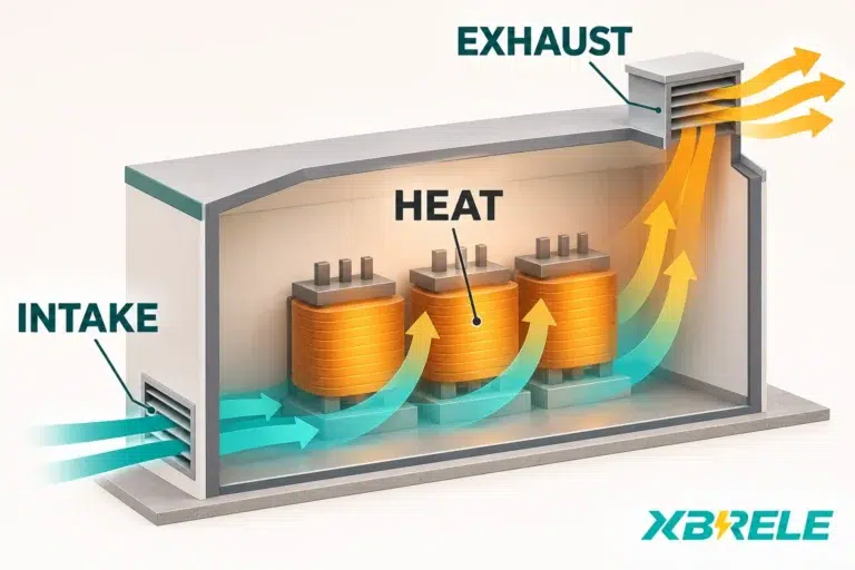
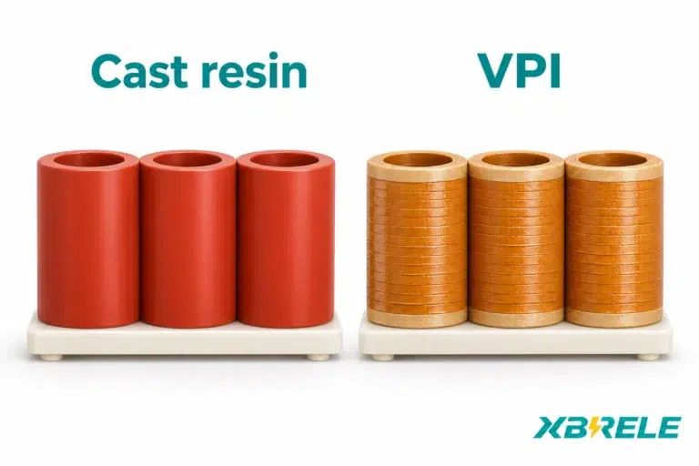
Consider a plant that is normally unattended, with a cast-resin dry-type transformer in a ventilated enclosure and a controller that commands an enclosure fan contactor. The original specification asks for a fan output, an alarm output and a trip output — and nothing else. The fan command has no return signal.
The consequence unfolds predictably. The fan contactor coil fails open during a summer weekend. Load stays high. The controller continues to command cooling and sees no reason to doubt itself, because it never had a way to observe the fan. Winding temperature climbs, the alarm operates — into an unstaffed control room — and later the trip operates. On Monday the site has an overtemperature trip, a transformer that must be inspected, and no way to distinguish “the fan never ran” from “the winding sensor drifted” from “the airflow path was blocked,” because every one of those produces a similar trend in a single channel with no corroborating information.
What a changed specification solves, item by item:
The verification that makes any of this meaningful is a record of simulated inputs and observed outputs, produced under the equipment manufacturer’s written procedure and the site’s isolation rules. The table below is a specification-level list of what such a record should cover; the actual test method belongs to the qualified procedure, not to this article.
| Verification item | What it proves | Evidence expected |
|---|---|---|
| Channel reading against a simulated resistance at two or more points | The input, wiring and linearisation agree with a known reference within the declared tolerance | Signed record with injected value, indicated value and the instrument used |
| Fan-on and fan-off operation, including the band | The cooling decision switches at the intended values and does not chatter | Observed relay state at rising and falling simulation |
| Alarm threshold operation and reset behaviour | Alarm asserts and clears as specified | Relay state and annunciator/SCADA point |
| Trip threshold operation and specified latch/reset | Trip asserts and clears or latches according to the specified reset design | Relay state, latch status, reset action recorded |
| Sensor open and short response | The channel is reported as faulty rather than as a temperature | Controller indication and output state for each fault type |
| Loss of auxiliary supply | Relay states at de-energisation match the chosen failsafe convention | Observed contact states with supply removed, coordinated with panel design |
| Downstream proof | The trip contact actually operates the breaker’s trip circuit, the fan contact actually starts the motor, alarms actually reach their destinations | Actual breaker operation and resulting position, motor running proof, SCADA point change; record trip-circuit supervision separately as continuity/health evidence |
The last row is the one that is most often skipped and most often matters. Everything upstream can pass while the command goes nowhere.
Two things are worth settling before a quote is requested: the transformer’s cooling configuration and declared capacity in each mode, and the panel’s interface list.
XBRELE’s cast-resin dry-type transformer catalogue page is the route for the transformer side. Ask for project-specific agreed no-load and load losses, the cooling arrangement and the rating that applies to each cooling mode, plus the general arrangement and enclosure data — rather than lifting figures from a general catalogue table, which cannot reflect a particular design’s ventilation and enclosure.
For the control side, a brief containing the sensor count and positions, the required fan, alarm, trip and fault outputs with their load details, the auxiliary supply, the failsafe convention, the reset philosophy and the SCADA point list is enough to define the boundary precisely. That can be submitted through the XBRELE contact page.
No. A Pt100 is a platinum resistance thermometer with 100 Ω at 0 °C and a gradual, near-linear rise in resistance with temperature, so it delivers a continuous temperature value and the controller can compare that value against fan, alarm and trip settings. A PTC thermistor is a threshold device whose resistance stays low until the element reaches its nominal response temperature and then rises sharply, so it delivers a step that means “this point has passed its reference temperature” and nothing more. They require different input types, produce different information, and cannot be substituted for one another at the same channel.
Not necessarily — and that is exactly why the two states must be kept apart. A sensor fault means the temperature at that point is unknown: the element, cable, terminal or controller input may have failed. A real hot condition can occur at one location or across several phases. Treating a fault as a temperature reading destroys the diagnostic value of the alarm; treating it as nothing at all leaves the winding unmonitored. The right response is a written project policy — alarm only, alarm with load restriction, or trip — chosen for whether the site is attended and whether the transformer can safely run unmeasured.
No. The controller switches a fan; it does not establish a rating. Forced cooling raises capacity only because the transformer’s thermal design — duct geometry, insulation system, winding construction — was engineered and demonstrated for that cooling mode. The rating that applies with forced cooling is manufacturer data tied to a specific design, and it has to be requested and agreed as project information. Adding a fan and a controller to a naturally cooled unit changes its cooling, but nothing about the declared capacity that follows from it.
Because the insulation class is a classification of the insulation system’s thermal endurance — the temperature index at which its expected service life is rated, such as the familiar Class F and Class H designations — and not an operating limit for a winding at a specific point. The trip setting has to be derived from the transformer manufacturer’s temperature-rise design and loading guidance, allowing for the fact that an embedded sensor reads one location rather than the true hot spot, and it must leave sensible margin between the fan band, the alarm and the trip so that each stage has room to act. Copying a number from an insulation class, or from another project’s controller, bypasses all of that reasoning.
Use the convention supported by the approved complete protection scheme. An energise-to-trip shunt coil requires a live trip supply when the command occurs; a failed controller supply or open wire does not itself energise that coil. A de-energise-to-trip design needs an energised healthy loop and a downstream device that responds as intended when the loop drops out. NC/NO contact names alone do not prove either behaviour. Verify controller power loss, trip-wire failure, downstream supply loss and sensor fault as separate cases, following the selected controller’s manual.