முழு விவரக்குறிப்புகள் வேண்டுமா?
அனைத்து சுவிட்ச்கியர் பாகங்களின் விரிவான வரைபடங்கள் மற்றும் தொழில்நுட்ப அளவுருக்களுக்கு, எங்கள் 2025 தயாரிப்புப் பட்டியலைப் பதிவிறக்கவும்.
பட்டியல் பெறுகஅனைத்து சுவிட்ச்கியர் பாகங்களின் விரிவான வரைபடங்கள் மற்றும் தொழில்நுட்ப அளவுருக்களுக்கு, எங்கள் 2025 தயாரிப்புப் பட்டியலைப் பதிவிறக்கவும்.
பட்டியல் பெறுகஅனைத்து சுவிட்ச்கியர் பாகங்களின் விரிவான வரைபடங்கள் மற்றும் தொழில்நுட்ப அளவுருக்களுக்கு, எங்கள் 2025 தயாரிப்புப் பட்டியலைப் பதிவிறக்கவும்.
பட்டியல் பெறுக
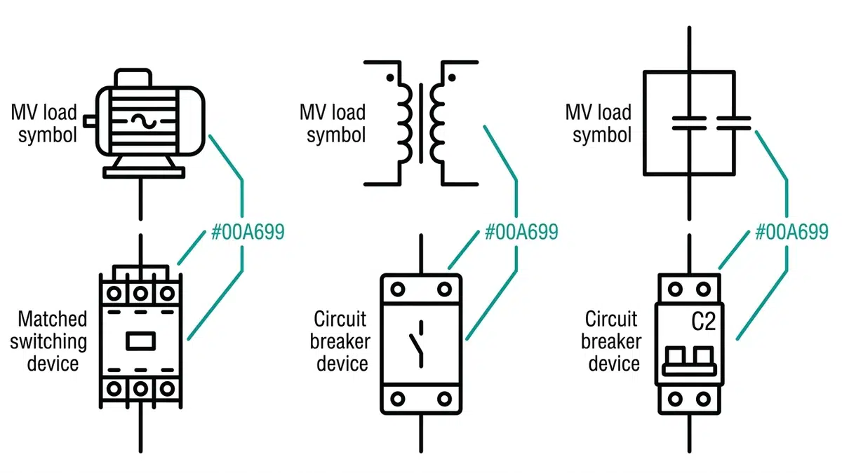
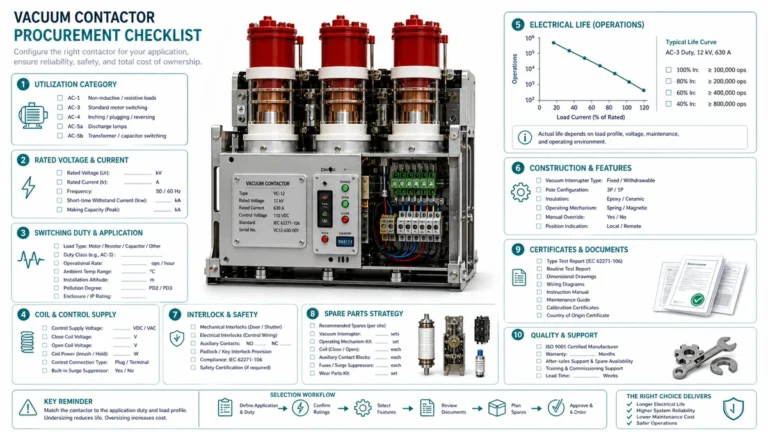
மோட்டார், டிரான்ஸ்ஃபார்மர் மற்றும் கேபசிட்டர் ஆகியவற்றின் சுவிட்ச்சிங் கடமைகள் எவ்வாறு வேறுபடுகின்றன என்பதையும், சரியான MV பிரேக்கர் அல்லது கான்டாக்டரைத் தேர்ந்தெடுப்பது எப்படி என்பதையும் அறிக.
நடுத்தர-வோல்டேஜ் (MV) மின் அமைப்புகளில், ஒரு குறிப்பிட்ட பயன்பாட்டிற்கு சரியான சுவிட்ச்சிங் சாதனத்தைத் தேர்ந்தெடுப்பதை விட அதிக விளைவுகளைக் கொண்ட சில முடிவுகளே உள்ளன. மோட்டார் ஸ்டார்ட்டிங்கிற்கு மிகவும் பொருத்தமான ஒரு சர்க்யூட் பிரேக்கர் அல்லது காண்டாக்டர், கேபசிட்டர் சுவிட்ச்சிங்கிற்குப் பயன்படுத்தும்போது பேரழிவு தரும் வகையில் தோல்வியடையலாம். அதே சமயம், டிரான்ஸ்ஃபார்மர் காந்தப்படுத்தும் மின்னோட்டத்தைத் துண்டிப்பதற்காக வடிவமைக்கப்பட்ட ஒரு சாதனம், ஆகாஸ்-தி-லைன் மோட்டார் ஸ்டார்ட்டிங்கின் கடுமையான இன்ரஷ் மின்னோட்டங்களுக்குப் போதுமானதாக இல்லாமல் போகலாம்.
கடல் கடற்கரை ஓரத்தில் உள்ள பெட்ரோகெமிக்கல் வசதிகளில் இருந்து நெவாடாவில் உள்ள சுரங்கச் செயல்பாடுகள் வரை, தொழில்துறை மின் அமைப்புகளுடன் நான் பணியாற்றிய எனது 18 ஆண்டுகளில், தவறாகப் பயன்படுத்தப்பட்ட சுவிட்ச்சிங் உபகரணங்களின் செலவுமிக்க விளைவுகளை நான் நேரில் கண்டிருக்கிறேன். ஒரு எஃகு பதப்படுத்தும் ஆலையில் நடந்த ஒரு மறக்க முடியாத சம்பவத்தில், மோட்டார் சுவிட்ச்சிங்கிற்காக மதிப்பிடப்பட்ட ஒரு வெற்றிட கான்டாக்டர், பவர் ஃபாக்டர் திருத்த கபேசிட்டர் பேங்கில் நிறுவப்பட்டது. மூன்று மாதங்களுக்குள், தொடர்புகள் செயலிழக்கும் அளவுக்கு அரிக்கப்பட்டு, இது திட்டமிடப்படாத மின்வெட்டுக்கு வழிவகுத்தது, மேலும் அந்த ஆலைக்கு உற்பத்தி இழப்பின் மூலம் $200,000-க்கும் அதிகமான செலவை ஏற்படுத்தியது.
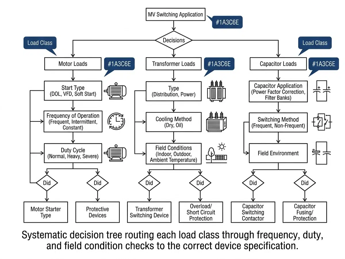
இந்தக் கட்டுரை, சுவிட்ச்சிங் கடமைகளைப் பொருத்தமான உபகரணங்களுடன் பொருத்துவதற்கான ஒரு முறையான முடிவெடுக்கும் கட்டமைப்பை வழங்குகிறது. மோட்டார், டிரான்ஸ்ஃபார்மர் மற்றும் கேபசிட்டர் சுவிட்ச்சிங் பயன்பாடுகளுடன் தொடர்புடைய தனித்துவமான மின் அழுத்தங்களை நாம் ஆராய்வோம், ஒவ்வொரு கடமை வகையின் பின்னணியில் உள்ள இயற்பியலை ஆராய்வோம், மேலும் பொறியாளர்கள் மற்றும் வசதி மேலாளர்கள் களத்தில் பயன்படுத்தக்கூடிய நடைமுறைத் தேர்வு அளவுகோல்களை உருவாக்குவோம்.
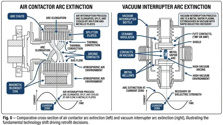
ஒவ்வொரு சுவிட்ச்சிங் பயன்பாடும் துண்டிக்கும் சாதனங்களின் மீது தனித்துவமான மின் மற்றும் இயந்திர அழுத்தங்களை ஏற்படுத்துகிறது. இந்த அழுத்தங்கள் மூன்று முக்கியமான கட்டங்களின் போது வெளிப்படுகின்றன: ஆற்றல்மயமாக்கல் (மூடுதல்), நிலையான செயல்பாடு, மற்றும் ஆற்றல் நீக்கம் (திறத்தல்). பயன்பாட்டு வகைகளுக்கு ஏற்ப இந்த அழுத்தங்களின் தீவிரம் மற்றும் தன்மை வியத்தகு முறையில் மாறுபடுகின்றன.
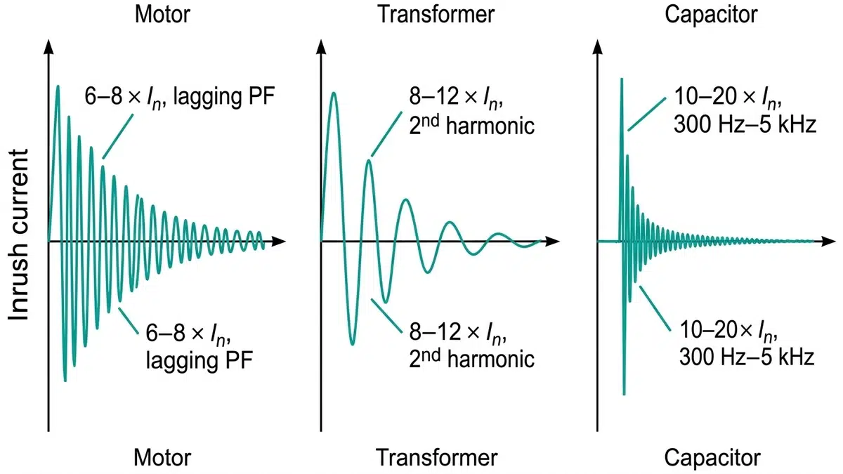
மோட்டார் மாற்றுதல் தொடக்கத்தின் போது ஏற்படும் அதிக உள்நுழைவு மின்னோட்டங்களை (வழக்கமாக மதிப்பிடப்பட்ட மின்னோட்டத்தை விட 6-8 மடங்கு), லாக்ட் ரோட்டர் நிலைகளை, மற்றும் மோட்டார்கள் நிற்கும்போது மீண்டும் வழங்கும் ஆற்றலை நிர்வகிப்பதை இது உள்ளடக்கியது. சுமை முக்கியமாக காந்தமின்னழுத்தத் தன்மை கொண்டது, தொடக்கத்தின் போது சக்தி காரணிகள் பெரும்பாலும் 0.3-க்குக் குறைவாக இருக்கும்.
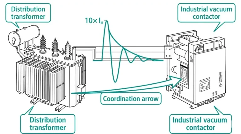
மாற்றக்கிணைப்பு மதிப்பிடப்பட்ட மின்னோட்டத்தின் 8-12 மடங்கு அடையும் காந்தப்படுத்துதல் திடீர் மின்னோட்டங்கள், இணை வரிசையில் மின்மாற்றிகளை மின்னேற்றம் செய்யும்போது ஏற்படும் ஒத்திசைவு திடீர் மின்னோட்டம், மற்றும் ஆபத்தான மின்னழுத்த தற்காலிகங்களை ஏற்படுத்தக்கூடிய சிறிய காந்தப்படுத்துதல் மின்னோட்டங்களின் குறுக்கீடு போன்ற சவால்களை இது முன்வைக்கிறது.
கண்டென்ச்டர் மாற்றுதல் ஒருவேளை மிகவும் கடுமையான தற்காலிக நிலைகளை உருவாக்குகிறது; இது சில கிலோஹெர்ட்ஸ் அதிர்வெண்களில் மதிப்பிடப்பட்ட மின்னோட்டத்தை விட 100 மடங்கு அதிகமான உள்நுழைவு மின்னோட்டங்களையும், திறக்கும் போது அமைப்பு மின்னழுத்தத்தின் ஒரு அலகிற்கு 2-3 வரை அடையும் உயர்-அதிர்வெண் மறுதாக்குதல் மின்னழுத்தங்களையும் உருவாக்குகிறது.
இந்தப் பயன்பாடுகள் ஏன் வேறுபடுகின்றன என்பதைப் புரிந்துகொள்ள, அவற்றின் அடிப்படையிலுள்ள இயற்பியலை ஆராய வேண்டும். மோட்டார்கள் தொடங்கும் போது அதிக இம்ப்பெடன்ஸைக் காட்டுகின்றன, ஏனெனில் சுழலி இன்னும் எதிர்-மின்விசை (counter-EMF) உருவாக்கவில்லை. மோட்டார் வேகமெடுக்கும்போது, இம்ப்பெடன்ஸ் அதிகரித்து, மின்னோட்டம் ஒரு தனித்துவமான எக்ஸ்போனென்ஷியல் சரிவு வளைவுக்கு ஏற்ப குறைகிறது.
மாற்றிகள், மின்னழுத்த அலைக்கற்றை சாதகமற்ற ஒரு புள்ளியில் ஆற்றல் பெறும்போது, மையக் காந்தநிறைவின் காரணமாக திடீர் மின்னோட்டப் பாய்ச்சலை அனுபவிக்கின்றன. மின்னழுத்தம் பூஜ்ஜியத்தைக் கடக்கும் நேரத்தில் மாற்றியை ஆற்றல் பெற்றால், மேலும் ஆரம்ப அரைக்காலம் உருவாக்கும் அதே துருவத்தன்மை கொண்ட எஞ்சிய காந்தப் பாய்மம் மையத்தில் இருந்தால், மையம் காந்தநிறைவடைந்து, காந்தப்படுத்துதல் தடை கிட்டத்தட்ட சுருள் மின்தடைக்குக் குறைந்துவிடும்.
கondensators மிக உச்சகட்ட மின்பாய்வு நிகழ்வை உருவாக்குகின்றன, ஏனெனில் அவை உயர்-ஆவெண்சி இடைநிலை நிலைகளுக்கு ஒரு குறுகிய சுற்று இணைப்பாகச் செயல்படுகின்றன. ஒரு condensator வங்கி மின்னேற்றப்படும்போது, மின்சுற்றின் இயற்கை அதிர்வெண் (மூலத்தின் காந்தமடக்கம் மற்றும் மின்தேக்கத்தால் தீர்மானிக்கப்படுகிறது) மின்பாய்வு மின்னோட்டத்தின் அதிர்வெண் மற்றும் அளவை நிர்ணயிக்கிறது.
மோட்டாரைத் தொடங்கும் முறை, சுவிட்ச்சிங் சாதனங்களுக்கான தேவைகளைக் கணிசமாகப் பாதிக்கிறது. லைன் முழுவதும் (DOL) தொடங்குதல் மிகக் கடுமையான சுமையை ஏற்படுத்துகிறது, இது முழு பூட்டப்பட்ட-ரோட்டர் மின்னோட்டத்தை உருவாக்கி உடைக்கக்கூடிய சாதனங்களைத் தேவைப்படுத்துகிறது. குறைக்கப்பட்ட மின்னழுத்தத் தொடங்குதல் முறைகள்—ஆட்டோட்ரான்ஸ்ஃபார்மர், ரியாக்டர், அல்லது திடநிலை—இந்த அழுத்தங்களைக் குறைக்கின்றன, ஆனால் அவற்றை முற்றிலுமாக நீக்கவில்லை.
MV மோட்டார்களுக்கு, IEEE C37.20.7 மற்றும் IEC 62271-106 ஆகியவை மோட்டார் சுவிட்ச்சிங் பயன்பாடுகளுக்கான குறிப்பிட்ட சோதனை நெறிமுறைகளை வரையறுக்கின்றன. இந்தத் தரநிலைகள் பின்வருவனவற்றைக் குறிப்பிடுகின்றன:
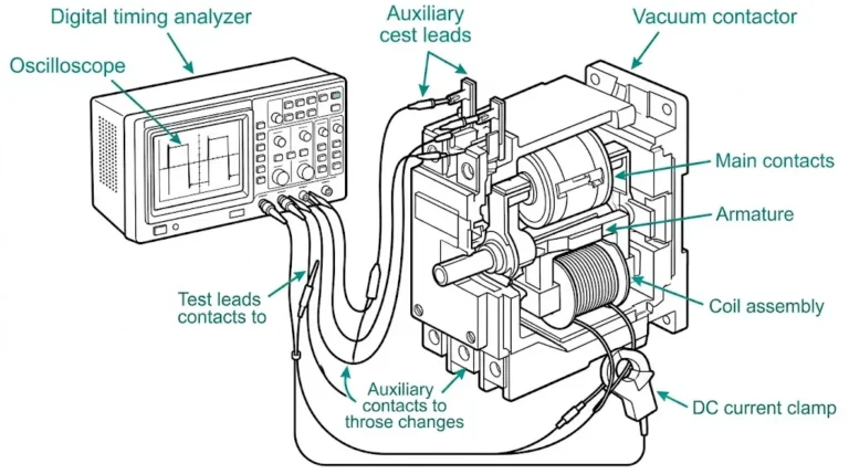
நவீன MV மோட்டார் சுவிட்ச்சிங் முதன்மையாக வெற்றிடத் துண்டிப்புத் தொழில்நுட்பத்தைப் பயன்படுத்துகிறது. வெற்றிடத் தொடர்பிகள் மற்றும் சுற்று முறிப்பான்கள் மோட்டார் பயன்பாட்டிற்கு பல நன்மைகளை வழங்குகின்றன:
மோட்டார் சுவிட்ச்சிங்கிற்கு SF6 சுவிட்ச்ஜியர் சாத்தியமானதாகவே உள்ளது, ஆனால் அது எந்தவொரு குறிப்பிட்ட நன்மையையும் வழங்குவதில்லை, மேலும் SF6-இன் புவி வெப்பமயமாதல் திறன் காரணமாக சுற்றுச்சூழல் கவலைகளையும் கொண்டுள்ளது.
மோட்டார் சுவிட்ச்சிங் உபகரணங்களைத் தேர்ந்தெடுக்கும்போது, பொறியாளர்கள் சரிபார்க்க வேண்டும்:
மாற்றியின் சுவிட்ச்சிங் ஒரு முரண்பாட்டைக் காட்டுகிறது: இதில் சம்பந்தப்பட்ட மின்னோட்டங்கள் ஒப்பீட்டளவில் சிறியவை (காந்தப்படுத்துதல் மின்னோட்டத்திற்கு பொதுவாக மதிப்பிடப்பட்ட மின்னோட்டத்தில் 1-2%), ஆனாலும், பிழை மின்னோட்டங்களைத் துண்டிப்பதை விட சுவிட்ச்சிங் பணி அதிக சேதத்தை ஏற்படுத்தக்கூடும். இது மின்னோட்டத் துண்டிப்பாலும் அதன் விளைவாக ஏற்படும் மின்னழுத்த தற்காலிகங்களாலும் ஏற்படுகிறது.
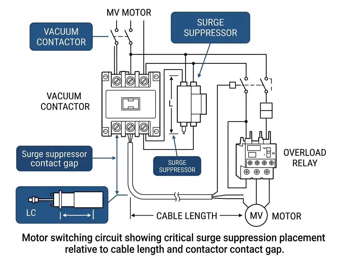
ஒரு காந்தப்பூட்டு மின்தடை (vacuum அல்லது SF6) சிறிய காந்தப்பூட்டு மின்னோட்டத்தைச் சுமக்கும்போது திறக்கப்படும்போது, இயற்கையான மின்னோட்டத்தின் பூஜ்ஜியத்திற்கு முன்பே மின்மின்னல் அலை அணைந்துவிடக்கூடும். இந்த முன்கூட்டிய இடைநிறுத்தம்—மின்னோட்ட வெட்டுதல்—மாற்றியின் காந்தப்புலத்தில் ஆற்றலைச் சேமிக்கிறது. இந்த ஆற்றல் பின்வரும் விதிப்படி ஒரு மின்னழுத்த தற்காலிகமாக மாறுகிறது:
V = I × √(L/C)
இதில் I என்பது துண்டிக்கப்பட்ட மின்னோட்டத்தின் அளவு, L என்பது மின்மாற்றியின் தூண்டல் மின்தடை, மற்றும் C என்பது செயல்திறன் மிக்க மின்தேக்கம் ஆகும். உச்ச மின்னழுத்தங்கள் ஒரு அலகிற்கு 3-5 வரை எட்டக்கூடும், இது மின்மாற்றியின் காப்புப் பூச்சிற்கு சேதத்தை ஏற்படுத்தக்கூடும்.
ஏற்கனவே மின்சாரம் வழங்கப்பட்ட டிரான்ஸ்ஃபார்மர்களுடன் இணைத்து ஒரு டிரான்ஸ்ஃபார்மருக்கு மின்சாரம் வழங்கும்போது, ஒத்திசைவு மின்சாரப் பாய்ச்சல் ஏற்படலாம். மின்சாரம் வழங்கும் டிரான்ஸ்ஃபார்மரின் மின்சாரப் பாய்ச்சல், மூலத் தடையின் குறுக்கே ஒரு மின்னழுத்த வீழ்ச்சியை உருவாக்குகிறது. இது இயங்கிக்கொண்டிருக்கும் டிரான்ஸ்ஃபார்மர்களைப் பகுதி அளவு மின்சாரம் இழக்கச் செய்து, அவை கூடுதல் காந்தப்படுத்துதல் மின்னோட்டத்தை ஈர்க்கக் காரணமாகிறது. இந்த நிகழ்வு, அதிக மின்சாரப் பாய்ச்சல் நீடிக்கும் காலத்தை நீட்டிக்கிறது, மேலும் சுவிட்ச்சிங் சாதனங்களின் அளவைத் தீர்மானிக்கும்போது இதைக் கருத்தில் கொள்ள வேண்டும்.
டிரான்ஸ்ஃபார்மர் சுவிட்ச்சிங் தற்காலிக நிலைகளைப் பல அணுகுமுறைகள் குறைக்கின்றன:
மின்சக்தி அமைப்புகளில், மின்தேக்கி மாற்றுதல் என்பது மிகவும் கடுமையான மாற்றுப் பணியாகும். பல மின்தேக்கி வங்கிಗಳು ஒரு பொதுவான பேஸைப் பகிர்ந்து கொள்ளும் பேக்-டு-பேக் உள்ளமைப்புகளில், இந்தச் சவால் வியத்தகு முறையில் தீவிரமடைகிறது.
தனிமைப்படுத்தப்பட்ட ஒரு கப்பாசிட்டர் பேங்கில் இணைக்கும்போது, இன்ரஷ் கரண்ட் மூலத்தின் இண்டக்டன்ஸால் கட்டுப்படுத்தப்படுகிறது, இது பொதுவாக மிதமான இன்ரஷ் அளவுகளுக்கு (இருப்பினும் உயர் அதிர்வெண்ணில்) வழிவகுக்கிறது. இருப்பினும், பேக்-டு-பேக் ஸ்விட்ச்சிங்கில், ஏற்கனவே ஆற்றல் பெற்ற கப்பாசிட்டர் பேங்குகள் குறைந்த-இம்ப்பெடன்ஸ் உயர்-அதிர்வெண் கரண்ட் மூலத்தை வழங்குகின்றன. 2-10 kHz அதிர்வெண்களில் இன்ரஷ் கரண்ட்கள் மதிப்பிடப்பட்ட கரண்டை விட 100 மடங்கு அதிகமாக இருக்கலாம்.
தொடர்-தொடர் சுவிட்ச்சிங்கிற்கான உச்ச உள்ளீட்டு மின்னோட்டத்தை மதிப்பிடலாம்:
I_peak = V × √(C_equivalent/L_connecting)
இங்கு L_connecting என்பது மின்னேற்றத் தொகுதிகளை இணைக்கும் பேஸின் தூண்டல் மின்தடத்தை மட்டும் குறிக்கிறது—இது பொதுவாக மைக்ரோஹென்றிகளில் அளவிடப்படும் ஒரு மிகச் சிறிய மதிப்பு ஆகும்.
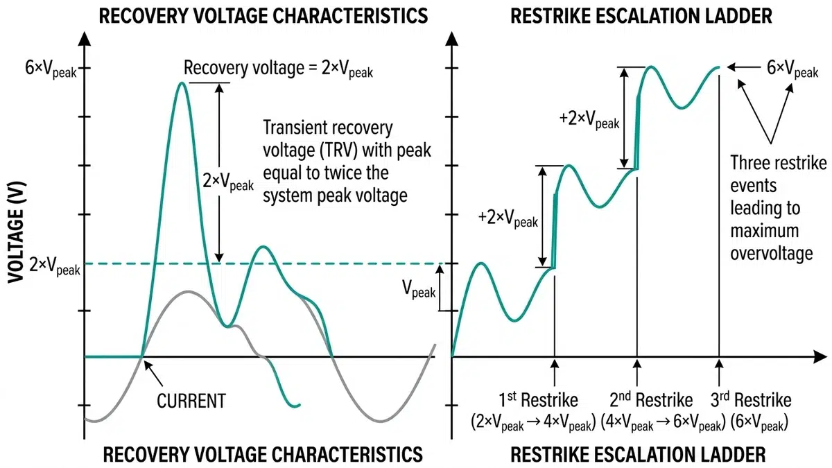
கண்டென்சரை மின்விசையற்றப்படுத்தும்போது, இயற்கையான பூஜ்ஜியக் கடத்தலில் மின்னோட்டத் துண்டிப்பு ஏற்படுவதால், கண்டென்சர் உச்ச அமைப்பு மின்னழுத்தத்தில் சார்ந்திருக்கும். ஒரே அரைக்காலத்திற்குள், அமைப்பு மின்னழுத்தம் எதிர் துருவத்தை அடைந்து, திறக்கும் தொடர்புகளுக்கு எதிராக ஒரு அலகுக்கு சுமார் 2 என்ற அளவில் மின்னழுத்தத்தை உருவாக்குகிறது.
இடைமறிப்பான் மீண்டும் மின்விளிம்பை ஏற்படுத்துமானால் (மீண்டும் மின்விளிம்பை நிறுவினால்), மின்தேக்கி மின்னழுத்தம் வேகமாக மாறுகிறது. மற்றொரு முறை மீண்டும் மின்விளிம்பு ஏற்பட்டால், மின்னழுத்தம் மேலும் அதிகரிக்கக்கூடும். மின்னழுத்த அதிகரிப்பு எனப்படும் இந்த நிகழ்வு, ஒரு அலகிற்கு 4-5-ஐ விட அதிகமான மின்னழுத்தங்களை உருவாக்கி, உபகரணங்களின் பேரழிவுத் தோல்வியை ஏற்படுத்தக்கூடும்.
IEC 62271-100 மற்றும் IEEE C37.09 ஆகியவை கபாசிட்டர் சுவிட்ச்சிங் சாதனங்களுக்கான குறிப்பிட்ட தேவைகளை வரையறுக்கின்றன:
சுமையைத் தெளிவாக வரையறுப்பதன் மூலம் தொடங்குங்கள்:
மாற்றும் அதிர்வெண் உபகரணத் தேர்வை வியத்தகு முறையில் பாதிக்கிறது:
| ஒரு நாளைக்கு செயல்பாடுகள் | உபகரண வகுப்பு |
|---|---|
| ஐந்துக்குக் குறைவான | பொருத்தமான சுற்று முறிப்பான் |
| 5-30 | மேம்படுத்தப்பட்ட ஆயுட்காலம் கொண்ட கான்டாக்டர் அல்லது சர்க்யூட் பிரேக்கர் |
| 30-100 | வெற்றிட தொடர்பி தேவை |
| நூறு | நீட்டிக்கப்பட்ட ஆயுட்காலத் தொடர்புகளுடன் கூடிய வெற்றிடத் தொடர்பி |
ஒவ்வொரு பயன்பாட்டு வகைக்கும், கணக்கிடு:
மோட்டார்கள்:
– பூட்டப்பட்ட ரோட்டர் மின்னோட்டம் = (மோட்டார் HP × 1000) / (√3 × V × PF_start × செயல்திறன்)
– பொதுவான தோராயமான மதிப்பு: LRC = 6 × FLA
மாற்றான்கள்:
– அதிகபட்ச உள்ளேற்ற மின்னோட்டம் ≈ 8-12 × மதிப்பிடப்பட்ட மின்னோட்டம் (முதல் அரை-சுற்று உச்சம்)
– கால அளவு: X/R விகிதத்தைப் பொறுத்து 100ms முதல் பல வினாடிகள் வரை
கondensators (பின்புறம்-பின்புறம்):
– உச்ச உள்ளோட்டம் = 1.41 × V_L-L × √(C1 × C2 / (C1 + C2)) / √L_connecting
– அதிர்வெண் = 1 / (2π × √(L_connecting × C_equivalent))
மோட்டார் கிளை:
– ஒரு நாளைக்கு 30-க்கு மேற்பட்ட இயக்கங்கள் இருந்தால் → வெற்றிட கான்டாக்டர்
– செயல்பாடுகள் ≤ 30/நாள் மற்றும் கோளாறு கடமை < 50kA → வெற்றிட சுற்று முறிவி
– பிழை மின்னோட்டம் > 50kA எனில் → மோட்டார் சுவிட்ச்சிங் மதிப்பீட்டுடன் கூடிய SF6 சர்க்யூட் பிரேக்கர்
மாற்றாக்கி கிளை:
– டிரான்ஸ்ஃபார்மர் 5MVA-க்கு குறைவாக மற்றும் தனிமைப்படுத்தப்பட்டிருந்தால் → சர்ஜ் அரேஸ்டர்களுடன் கூடிய நிலையான சர்க்யூட் பிரேக்கர்
– டிரான்ஸ்ஃபார்மர் ≥ 5MVA ஆக இருந்தால் அல்லது இணை வரிசைச் செயல்பாடு → கட்டுப்படுத்தப்பட்ட சுவிட்ச்சிங்குடன் கூடிய சர்க்யூட் பிரேக்கர்
– அடிக்கடி மாற்றுவது அவசியமானால் → செருகுவதற்கு முந்தைய மின்தடைகளைச் சேர்க்கவும்
கண்டெய்னர் கிளை:
– தனிமைப்படுத்தப்பட்ட வங்கி என்றால் → C1/C2 மதிப்பீட்டுடன் கூடிய சர்க்யூட் பிரேக்கர் (குறைந்தபட்சம்)
– தொடர்ச்சியாக ஏற்பட்டால் → மின்சாரத்தைக் கட்டுப்படுத்தும் ரியாக்டர்களுடன் கூடிய C2-மதிப்பீட்டு சர்க்யூட் பிரேக்கர்
– மாறும் அதிர்வெண் > 10/நாள் எனில் → C2 மதிப்பீட்டுடன் கூடிய வெற்றிட கான்டாக்டர்
அரிசோனாவில் உள்ள ஒரு செப்புச் சுரங்கத்திற்கு, பத்து 4,160V, 2,500HP பந்து அரைக்கும் மோட்டார்களுக்கு ஸ்விட்ச்சிங் உபகரணங்கள் தேவைப்பட்டன. ஒவ்வொரு மோட்டாரும் ஒரு நாளைக்கு 6-8 முறை லைன் முழுவதும் நேரடியாகத் தொடங்கி இயங்கும். ஆரம்பகால விவரக்குறிப்புகளின்படி வெற்றிட சர்க்யூட் பிரேக்கர்கள் தேவைப்பட்டன.
பகுப்பாய்வு:
– முழு சுமை மின்னோட்டம்: ஒரு மோட்டார்க்கு 310A
– பூட்டப்பட்ட ரோட்டர் மின்னோட்டம்: 1,860A (6× FLA)
– அறுவை சிகிச்சைகள்: ஒரு நாளைக்கு 6-8 × 365 நாட்கள் = ஆண்டுக்கு 2,190-2,920 அறுவை சிகிச்சைகள்
– 20 ஆண்டு ஆயுட்காலம்: 44,000-58,400 அறுவை சிகிச்சைகள்
தீர்வு:
அதிக செயல்பாட்டு எண்ணிக்கையைக் கருத்தில் கொண்டு, 1 மில்லியன் செயல்பாட்டுத் திறன் கொண்ட வெற்றிட தொடர்பிகள், ஒவ்வொரு 10,000 செயல்பாடுகளுக்கும் தொடர்புகளை மாற்ற வேண்டிய மின்சுற்று முறிப்பான்களை விட மிகவும் சிக்கனமானதாக நிரூபிக்கப்பட்டன. அந்த சுரங்கம், மேல்நிலை உருகி ஒருங்கிணைப்புடன் கூடிய வெற்றிட தொடர்பிகளை நிறுவி, வாழ்க்கைச் சுழற்சிச் செலவை 40% குறைத்தது.
ஒரு பிராந்திய பயன்பாட்டு நிறுவனம் 13.8kV, 12MVAR கபாக்டர் வங்கிளில் தொடர்ச்சியான வெற்றிட சர்க்யூட் பிரேக்கர் செயலிழப்புகளைச் சந்தித்தது. விசாரணை, மின்னோட்டத்தைக் கட்டுப்படுத்தும் ரியாக்டர்கள் இல்லாமல் தொடர்ச்சியான சுவிட்ச்சிங் நிகழ்ந்ததை வெளிப்படுத்தியது.
பகுப்பாய்வு:
– கணக்கிடப்பட்ட தொடர் மின்பாய்ச்சல்: 4.2kHz-இல் 18kA உச்சம்
– சர்க்யூட் பிரேக்கர் மதிப்பீடு: 4kHz-இல் 10kA உச்ச உள்ளேற்றம்
– விளைவு: கடுமையான தொடர்பு அரிப்பு மற்றும் இறுதியில் மீண்டும் தாக்குதலால் ஏற்படும் தோல்வி
தீர்வு:
500μH மின்னோட்டத்தைக் கட்டுப்படுத்தும் ரியாக்டர்களைப் பொருத்தியது, உச்சக்கட்ட மின்னோட்டத்தை 6kA ஆகக் குறைத்தது, இது பிரேக்கரின் மதிப்பீடுகளுக்குள் நன்கு அடங்கும். மின்சாரப் பயன்பாட்டு நிறுவனமும் C2-மதிப்பீடு பெற்ற சர்க்யூட் பிரேக்கர்களுக்கு மேம்படுத்தியது, அடுத்த ஐந்து வருடக் கண்காணிப்புக் காலத்தில் ஏற்பட்ட தோல்விகளை நீக்கியது.
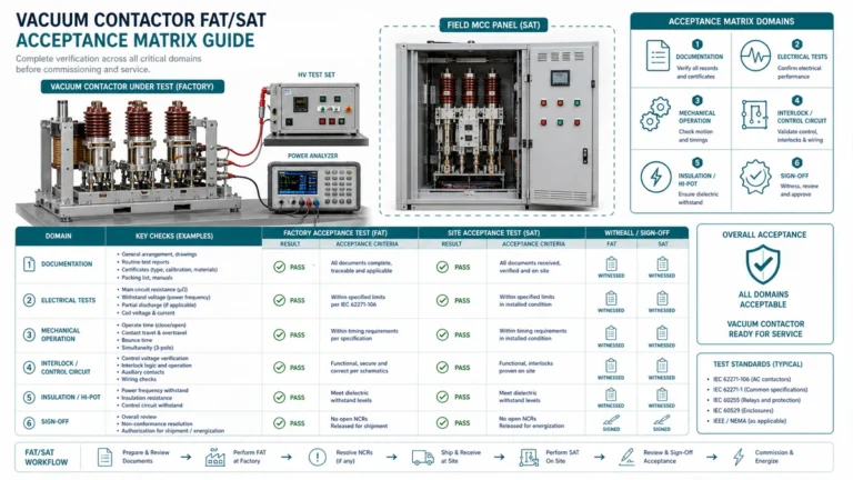
| விண்ணப்பம் | IEC தரநிலை | IEEE தரநிலை | முக்கியத் தேவைகள் |
|---|---|---|---|
| பொது மின்சுற்றுத் துண்டிக்கிகள் | ஐஇசி 62271-100 | ஐ.இ.இ. C37.09 | மதிப்பிடப்பட்ட பண்புகள், சோதனை முறைகள் |
| மோட்டார் மாற்றுதல் | ஐஇசி 62271-106 | ஐ.இ.இ.இ சி37.20.7 | கான்டாக்டர் தேவைகள், ஆயுள் |
| கண்டென்ச்டர் மாற்றுதல் | IEC 62271-100 இணைப்பு N | ஐ.இ.இ. C37.09 | C1/C2 வகைப்பாடு, TRV |
| மாற்றக்கிணைப்பு | ஐஇசி 62271-110 | ஐ.இ.இ.இ சி37.015 | உள்வாங்கல் சுமை மாற்றுதல் |
சரியான ஆவணப்படுத்தல், பணியாளர் மாற்றங்கள் மற்றும் வசதி மாற்றங்களுக்குப் பிறகும் சரியான உபகரணத் தேர்வு நீடிப்பதை உறுதி செய்கிறது:
[வெளி அதிகாரி குறிப்பு: சுவிட்ச்சிங் உபகரணங்களுக்கான தற்போதைய பதிப்புகளுக்கு IEEE தர நிர்ணய சங்கம் (standards.ieee.org)]
இல்லை, மோட்டார் சுவிட்ச்சிங் மற்றும் கான்டென்சர் சுவிட்ச்சிங் ஆகியவை அடிப்படையில் வெவ்வேறு அழுத்தங்களை ஏற்படுத்துகின்றன. மோட்டார் சுவிட்ச்சிங் என்பது குறிப்பிடத்தக்க காலத்திற்கு அதிக மின்னோட்டம், குறைந்த அதிர்வெண் கொண்ட இன்ரஷ் (inrush) மின்னோட்டத்தை உள்ளடக்கியது, அதேசமயம் கான்டென்சர் சுவிட்ச்சிங் திறக்கும் போது மிக உயர் அதிர்வெண் கொண்ட தற்காலிக மின்னோட்டங்களையும் (transients) கடுமையான மறு-அடிப்பு மின்னழுத்தங்களையும் (restrike voltages) உருவாக்குகிறது. மோட்டார்-சுவிட்ச்சிங் தரமதிப்பீடு பெற்ற பிரேக்கரில், கான்டென்சர் பயன்பாடுகளுக்குத் தேவையான மறு-அடிப்பு இல்லாத செயல்திறன் (restrike-free performance) இருக்காது. பயன்படுத்துவதற்கு முன்பு, சர்க்யூட் பிரேக்கர் குறிப்பிட்ட கான்டென்சர் சுவிட்ச்சிங் தரமதிப்பீடுகளை (IEC C1/C2 அல்லது IEEE கான்டென்சர் சுவிட்ச்சிங் மின்னோட்ட தரமதிப்பீடுகள்) கொண்டிருப்பதை எப்போதும் சரிபார்க்கவும்.
பல மின்தேக்கி வங்கிಗಳು ஒரு பொதுவான பஸ்ஸுடன் இணைக்கப்பட்டு, அவற்றைத் தனித்தனியாக மாற்றக்கூடிய எந்தவொரு உள்ளமைப்பிலும், பின்புற-இருபுற மாற்றும் கருத்தில் கொள்ளப்பட வேண்டும். இங்கு முக்கியமான காரணி வங்கிகளுக்கு இடையிலான தூண்டல் மின்தடை ஆகும்—இந்தத் தூண்டல் மின்தடை தோராயமாக 2mH-க்கும் குறைவாக இருந்தால், பின்புற-இருபுற உள்நுழைவு மின்னோட்டங்கள் தனிமைப்படுத்தப்பட்ட வங்கி மதிப்பீடுகளை மிஞ்சக்கூடும். பஸ் பார்கள், கேபிள்கள் மற்றும் ஏதேனும் உள்நோக்கத்துடன் இணைக்கப்பட்ட ரியாக்டர்கள் உட்பட இணைப்பு இண்டக்டன்ஸைக் கணக்கிடவும். சந்தேகம் இருக்கும்போது, பின்-முன் மதிப்பீடுகளைப் பயன்படுத்தவும்; தோல்வி விளைவுகளுடன் ஒப்பிடும்போது கூடுதல் செலவு மிகக் குறைவு.
இயல்பான மின்னோட்டத்தின் பூஜ்ஜியக் கடத்தலுக்கு முன்பே ஒரு துண்டிப்பான் மின்விசையை அணைக்கும்போது மின்னோட்டத் துண்டிப்பு ஏற்படுகிறது. வெற்றிடத் துண்டிப்பான்கள் மிகவும் எளிதில் பாதிக்கப்படக்கூடியவை, பொதுவாக 3-5 ஆம்பியர்களுக்குக் குறைவான மின்னோட்டங்களைத் துண்டிக்கின்றன. மோட்டார் சுவிட்ச்சிங்கிற்கு, இது குறைந்தபட்ச கவலையை ஏற்படுத்துகிறது, ஏனெனில் மோட்டார் மின்னோட்டங்கள் கணிசமானவை. இருப்பினும், டிரான்ஸ்ஃபார்மர் காந்தப்படுத்துதல் மின்னோட்டங்கள் பெரும்பாலும் வெட்டும் வரம்பிற்குள் வருகின்றன. வெட்டப்படும்போது, சேமிக்கப்பட்ட காந்த ஆற்றல், காப்புத் திறன்களை மீறக்கூடிய மின்னழுத்த தற்காலிக நிலைகளாக மாறுகிறது. இதைத் தணிப்பதற்கு, டிரான்ஸ்ஃபார்மர் முனைகளில் சர்ஜ் அரேஸ்டர்களைப் பொருத்துதல் மற்றும், உணர்திறன் மிக்க பயன்பாடுகளுக்கு, குறைந்த வெட்டும் பண்புகளுடன் கூடிய சர்க்யூட் பிரேக்கர்கள் அல்லது கட்டுப்படுத்தப்பட்ட சுவிட்ச்சிங் ஆகியவை அடங்கும்.
சர்க்யூட் பிரேக்கர்கள் அவ்வப்போது செயல்படுவதற்காக வடிவமைக்கப்பட்டுள்ளன—பொதுவாக காண்டாக்ட் பராமரிப்பு தேவைப்படுவதற்கு முன்பு 2,000-10,000 செயல்பாடுகளுக்கு மதிப்பிடப்படுகின்றன. காண்டாக்டர்கள் குறிப்பாக அடிக்கடி செயல்படுவதற்காக வடிவமைக்கப்பட்டுள்ளன, வெற்றிட காண்டாக்டர்கள் வழக்கமாக 1 மில்லியன் அல்லது அதற்கு மேற்பட்ட செயல்பாடுகளுக்கு மதிப்பிடப்படுகின்றன. பொருளாதார மாற்றம் பொதுவாக ஒரு நாளைக்கு 20-30 செயல்பாடுகளைச் சுற்றி நிகழ்கிறது. இந்த வரம்பிற்கு மேல், சர்க்யூட் பிரேக்கர் தொடர்புகளை மாற்றுவதோடு தொடர்புடைய பராமரிப்புச் செலவு மற்றும் செயலிழப்பு நேரமானது, பொதுவாக தொடர்புகளுக்கான ஆரம்பச் செலவுப் பிரீமியத்தை விட அதிகமாக இருக்கும். கூடுதலாக, தொடர்புகள் பொதுவாக வேகமான செயல்பாட்டை வழங்குகின்றன (சர்க்யூட் பிரேக்கர்களுக்கான 60-100ms-க்கு மாறாக 20-50ms-க்குள் மூடும்), இது மோட்டார் ஜாகிங் பயன்பாடுகளுக்குப் பயனுள்ளதாக இருக்கிறது.
SF6 சர்க்யூட் பிரேக்கர்கள் குறிப்பிட்ட சூழ்நிலைகளில் நன்மைகளை வழங்குகின்றன. மிக அதிக பிழை மின்னோட்டப் பயன்பாடுகளுக்கு (50kA-க்கு மேல்), வெற்றிடத் தொழில்நுட்பம் சவாலாக மாறும் மதிப்பீடுகளில் SF6 வடிவமைப்புகள் கிடைக்கக்கூடும். SF6 வெற்றிடத்தை விட குறைந்த மின்னோட்டத் துண்டிப்பு நிலைகளையும் காட்டுகிறது, இது டிரான்ஸ்ஃபார்மர் சுவிட்ச்சிங் பயன்பாடுகளுக்கு சாதகமாக இருக்கலாம். இருப்பினும், அதன் தீவிர புவி வெப்பமயமாதல் திறன் (CO2-ஐ விட 23,500 மடங்கு) காரணமாக சுற்றுச்சூழல் விதிமுறைகள் SF6 பயன்பாட்டை பெருகிய முறையில் கட்டுப்படுத்துகின்றன. பெரும்பாலான நவீன பயன்பாடுகள் வெற்றிடத் தொழில்நுட்பத்தை ஆதரிக்கின்றன, வெற்றிட மாற்று இல்லாத குறிப்பிட்ட உயர்-பணி பயன்பாடுகளுக்கு SF6 ஒதுக்கப்பட்டுள்ளது.
பல களக் குறிகாட்டிகள் பயன்பாட்டுப் பொருந்தாத்தன்மையைக் குறிப்பிடுகின்றன:
– அதிகப்படியான தொடர்பு தேய்மானம்உற்பத்தியாளரின் வளைவுகளை மீறிய தொடர்பு அணர்வு, அதிகப்படியான அழுத்தத்தைக் குறிக்கிறது.
– அடிக்கடி மீண்டும் அச்சிடப்பட்டதற்கான சான்றுகள்கண்டென்சர் சுவிட்ச்சிங் தொடர்புகளில் ஏற்படும் பள்ளத் தடம், போதுமான மறுதட்டச்சு இல்லாத திறனைக் குறிக்கிறது.
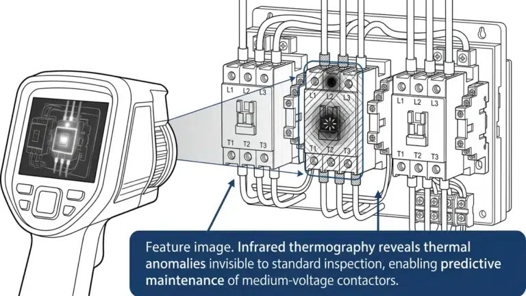
– அதிகரிக்கப்பட்ட இயக்க வெப்பநிலைகள்வெப்பப் படமெடுப்பு, அசாதாரண வெப்பமூட்டலைக் காட்டுவது, தற்போதைய மதிப்பீட்டுப் பொருத்தமின்மையைக் குறிக்கிறது.
– செயல்பாட்டு எண்ணிக்கையிலான முரண்பாடுகள்: பதிவுசெய்யப்பட்ட செயல்பாடுகள் எதிர்பார்க்கப்படும் கடமையை கணிசமாக விஞ்சினால், விண்ணப்பத்தை மறுமதிப்பீடு செய்யவும்
– நேரச் சிதைவுமூடும்/திறக்கும் நேரங்களில் ஏற்படும் மாற்றங்கள், அதிகப்படியான பயன்பாட்டினால் ஏற்படும் இயந்திரச் தேய்மானத்தைக் குறிக்கலாம்.
கட்டுப்படுத்தப்பட்ட சுவிட்ச்சிங் (அலைக்கட்டின் புள்ளி-சுவிட்ச்சிங்) சர்க்யூட் பிரேக்கர் மூடும் நேரத்தை உகந்த மின்னழுத்த கட்டம் கோணங்களுடன் ஒன்றிணைத்து, உள்நுழைவு மின்னோட்டத்தின் அளவைக் குறைக்கிறது. மூன்று-கட்ட டிரான்ஸ்ஃபார்மர்களுக்கு, கட்டுப்படுத்தி உகந்த காந்தப்புல நிலைகளை அடைய ஒவ்வொரு கட்டத்தின் மூடலை வரிசைப்படுத்துகிறது. நவீன கட்டுப்படுத்திகள் ±1ms துல்லியத்துடன் மூடும் செயலைச் செய்கின்றன, இது கட்டுப்பாடற்ற மூடல் செயல்முறையில் ஏற்படும் 8-12 மடங்கு மதிப்பிடப்பட்ட மின்னோட்டத்துடன் ஒப்பிடும்போது, மாற்றிக்குள் பாயும் திடீர் மின்னோட்டத்தை 1-2 மடங்காகக் குறைக்கிறது. இது மாற்றி மற்றும் சுற்று முறிப்பானின் ஆயுளை வியத்தகு முறையில் நீட்டிக்கிறது, மேலும் அடிக்கடி மாற்றப்படும் மாற்றுவிகளுக்கான திருப்பிச் செலுத்தும் காலம் பொதுவாக இரண்டு ஆண்டுகளுக்குள் இருக்கும்.
நடுத்தர வோல்டேஜ் (MV) அமைப்பு வடிவமைப்பில், பயன்பாட்டுப் பணித் தேவைகளுக்கு ஏற்ற சுவிட்ச்சிங் உபகரணங்களைத் தேர்ந்தெடுப்பது மிகவும் முக்கியமான முடிவுகளில் ஒன்றாகும். தவறான பயன்பாட்டின் விளைவுகள், உபகரணங்களின் விரைவான தேய்மானம் மற்றும் அதிகரித்த பராமரிப்புச் செலவுகள் முதல் பேரழிவுத் தோல்விகள் மற்றும் நீடித்த மின்வெட்டுகள் வரை பரவியுள்ளன.
சரியான வரிப் பொருத்தத்திற்கான அத்தியாவசியக் கொள்கைகள்:
மாற்றுப் பயன்பாட்டை ஒருபோதும் கருத வேண்டாம்மோட்டார், டிரான்ஸ்ஃபார்மர் மற்றும் கன்டென்சர் சுவிட்ச்சிங் ஆகியவை அடிப்படையில் வேறுபட்ட அழுத்தங்களை ஏற்படுத்துகின்றன, இதற்கு குறிப்பிட்ட மதிப்பீட்டு உபகரணங்கள் தேவைப்படுகின்றன.
குறிப்பிடுவதற்கு முன் கணக்கிடவும்வழக்கமான விதிகளைச் சார்ந்திருப்பதற்குப் பதிலாக, ஒவ்வொரு பயன்பாட்டிற்கும் இன்ரஷ் கணக்கீடுகளைச் செய்யவும்.
வாழ்க்கைச் சுழற்சி செயல்பாடுகளைக் கருத்தில் கொள்ளுங்கள்மாற்றும் அதிர்வெண், சுற்று முறிப்பான்கள் அல்லது தொடர்பான்கள் உகந்த வாழ்க்கைச் சுழற்சிச் செலவை வழங்குவதைத் தீர்மானிக்கிறது.
பொருத்தமான தரநிலைகளைப் பயன்படுத்துங்கள்IEC 62271 மற்றும் IEEE C37 தொடர் தரநிலைகள் ஒவ்வொரு பயன்பாட்டு வகைக்கும் குறிப்பிட்ட சோதனை அளவுகோல்களை வழங்குகின்றன.
முழுமையாக ஆவணப்படுத்துங்கள்எதிர்காலத்தில் சரியான மாற்றுப் பொருத்தத்தை உறுதிசெய்ய, கணக்கீட்டுப் பதிவுகளையும் உபகரண விவரக்குறிப்புகளையும் பராமரிக்கவும்.
இந்தக் கட்டுரையில் வழங்கப்பட்டுள்ள முடிவெடுக்கும் கட்டமைப்பை முறையாகப் பயன்படுத்துவதன் மூலம், பொறியாளர்கள் பயன்பாட்டுப் பொருத்தமின்மையால் ஏற்படும் அதிகப்படியான விளைவுகளைத் தவிர்த்து, அதன் முழு ஆயுட்காலம் முழுவதும் நம்பகமான சேவையை வழங்கும் சுவிட்ச்சிங் உபகரணங்களை நம்பிக்கையுடன் தேர்ந்தெடுக்க முடியும்.
ஆசிரியர் பற்றி: இந்தக் கட்டுரை, தொழில்துறை, பயன்பாட்டுத் துறை மற்றும் வணிகத் துறைகள் முழுவதும் நடுத்தர-வோல்டேஜ் சுவிட்ச்சிங் பயன்பாடுகளில் 18 ஆண்டுகால கள அனுபவத்தை அடிப்படையாகக் கொண்டது. இதில் 200-க்கும் மேற்பட்ட MV சுவிட்ச்கியர் நிறுவல்களை நேரடியாக ஆணையிடுதல் மற்றும் எண்ணற்ற சுவிட்ச்சிங் உபகரணத் தோல்விகளின் தடயவியல் பகுப்பாய்வு ஆகியவை அடங்கும்.