Need Full Specifications?
Download our 2025 Product Catalog for detailed drawings and technical parameters of all switchgear components.
Get CatalogDownload our 2025 Product Catalog for detailed drawings and technical parameters of all switchgear components.
Get CatalogDownload our 2025 Product Catalog for detailed drawings and technical parameters of all switchgear components.
Get Catalog
Learn how motor, transformer, and capacitor switching duties differ, and how to select the right MV breaker or contactor.
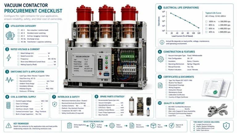
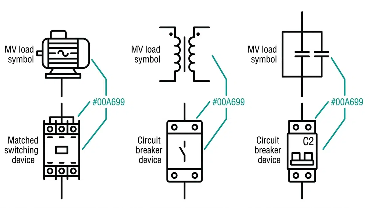
In medium-voltage (MV) electrical systems, few decisions carry more consequence than selecting the correct switching device for a specific application. A circuit breaker or contactor perfectly suited for motor starting may fail catastrophically when applied to capacitor switching, while a device designed for transformer magnetizing current interruption might prove inadequate for the severe inrush currents of across-the-line motor starting.
Throughout my 18 years working with industrial power systems—from petrochemical facilities along the Gulf Coast to mining operations in Nevada—I’ve witnessed firsthand the costly consequences of misapplied switching equipment. In one memorable incident at a steel processing plant, a vacuum contactor rated for motor switching was installed on a power factor correction capacitor bank. Within three months, the contacts had eroded to the point of failure, causing an unplanned outage that cost the facility over $200,000 in lost production.
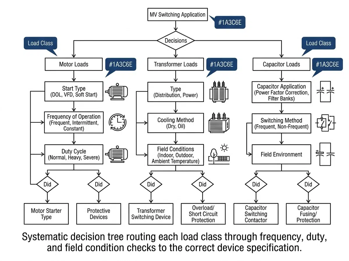
This article provides a systematic decision framework for matching switching duties to appropriate equipment. We’ll examine the distinct electrical stresses associated with motor, transformer, and capacitor switching applications, explore the physics behind each duty type, and develop practical selection criteria that engineers and facility managers can apply in the field.
Every switching application imposes unique electrical and mechanical stresses on interrupting devices. These stresses manifest during three critical phases: energization (closing), steady-state operation, and de-energization (opening). The severity and nature of these stresses vary dramatically between application types.
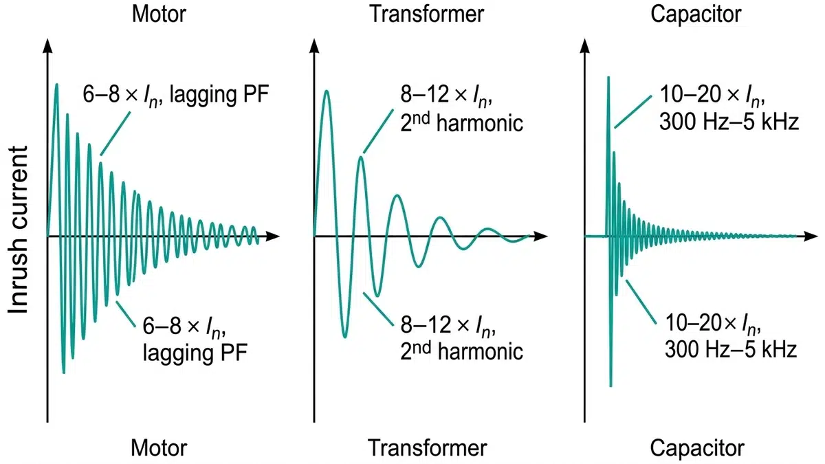
Motor switching involves managing high inrush currents during starting (typically 6-8 times rated current), locked rotor conditions, and the regenerative energy that motors can feed back during stopping. The load is predominantly inductive, with power factors during starting often below 0.3.
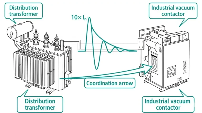
Transformer switching presents challenges from magnetizing inrush currents that can reach 8-12 times rated current, the phenomenon of sympathetic inrush when energizing transformers in parallel, and the interruption of small magnetizing currents that can cause dangerous voltage transients.
Capacitor switching creates perhaps the most severe transient conditions, with inrush currents that can exceed 100 times rated current at frequencies of several kilohertz, coupled with high-frequency restrike voltages during opening that can reach 2-3 per unit of system voltage.
Understanding why these applications differ requires examining the underlying physics. Motors present high impedance during starting because the rotor hasn’t yet developed counter-EMF. As the motor accelerates, impedance increases and current decreases following a characteristic exponential decay curve.
Transformers experience inrush due to core saturation when energized at an unfavorable point on the voltage wave. If the transformer is energized at voltage zero-crossing and the core has residual flux in the same polarity as the initial half-cycle would produce, the core saturates and the magnetizing impedance drops to essentially the winding resistance.
Capacitors present the most extreme inrush scenario because they represent a short circuit to high-frequency transients. When a capacitor bank is energized, the circuit’s natural frequency (determined by source inductance and capacitance) dictates the inrush current frequency and magnitude.
The method of motor starting significantly influences switching device requirements. Across-the-line (DOL) starting imposes the most severe duty, requiring devices capable of making and breaking the full locked-rotor current. Reduced voltage starting methods—autotransformer, reactor, or solid-state—reduce but don’t eliminate these stresses.
For MV motors, IEEE C37.20.7 and IEC 62271-106 define specific test protocols for motor switching applications. These standards specify:
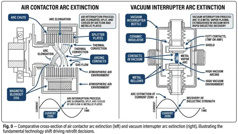
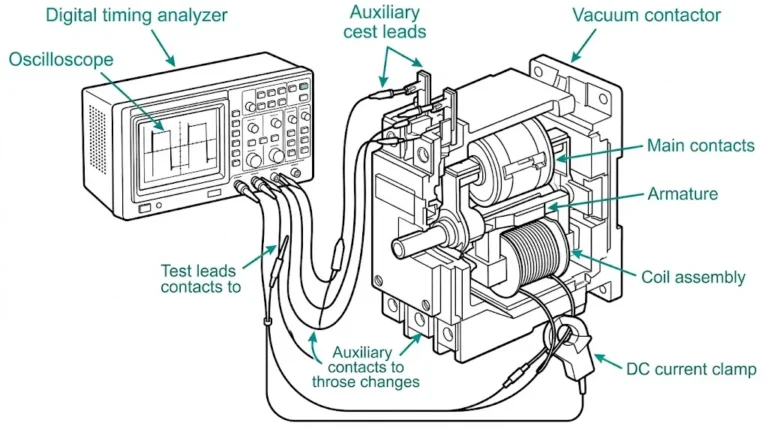
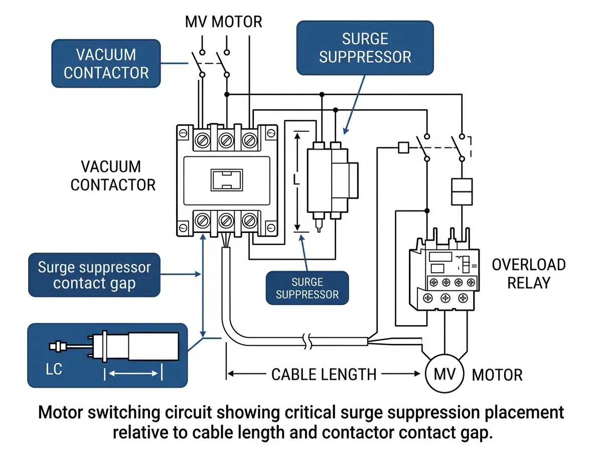
Modern MV motor switching predominantly uses vacuum interrupter technology. Vacuum contactors and circuit breakers offer several advantages for motor duty:
SF6 switchgear remains viable for motor switching but offers no particular advantage and carries environmental concerns due to SF6’s global warming potential.
When selecting motor switching equipment, engineers should verify:
Transformer switching presents a paradox: the currents involved are relatively small (typically 1-2% of rated current for magnetizing current), yet the switching duty can be more damaging than interrupting fault currents. This occurs because of current chopping and the resulting voltage transients.
When a vacuum or SF6 interrupter opens while carrying small magnetizing current, the arc may extinguish before the natural current zero. This premature interruption—current chopping—leaves energy stored in the transformer’s magnetic field. This energy converts to a voltage transient according to:
V = I × √(L/C)
Where I is the chopped current magnitude, L is the transformer inductance, and C is the effective capacitance. Peak voltages can reach 3-5 per unit, potentially damaging transformer insulation.
When energizing a transformer in parallel with already-energized transformers, sympathetic inrush can occur. The energizing transformer’s inrush current creates a voltage drop across the source impedance, which can partially de-energize the running transformers, causing them to draw additional magnetizing current. This phenomenon extends the duration of elevated inrush currents and must be considered when sizing switching devices.
Several approaches minimize transformer switching transients:
Capacitor switching represents the most severe switching duty in power systems. The challenge intensifies dramatically in back-to-back configurations, where multiple capacitor banks share a common bus.
When closing onto an isolated capacitor bank, inrush current is limited by source inductance, typically resulting in moderate inrush magnitudes (though still at high frequency). However, in back-to-back switching, the already-energized capacitor banks provide a low-impedance high-frequency current source. Inrush currents can exceed 100 times rated current at frequencies of 2-10 kHz.
The peak inrush current for back-to-back switching can be estimated:
I_peak = V × √(C_equivalent/L_connecting)
Where L_connecting represents only the inductance of the bus connecting the capacitor banks—typically a very small value measured in microhenries.
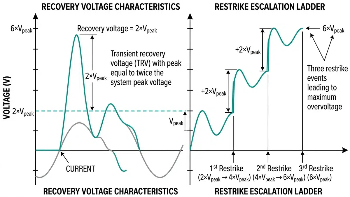
During capacitor de-energization, current interruption at the natural zero crossing leaves the capacitor charged at peak system voltage. Within one half-cycle, the system voltage reaches the opposite polarity, creating a voltage across the opening contacts of approximately 2 per unit.
If the interrupter restrikes (re-establishes the arc), the capacitor voltage rapidly reverses. If another restrike occurs, the voltage can escalate further. This phenomenon, called voltage escalation, can produce voltages exceeding 4-5 per unit, causing catastrophic equipment failure.
IEC 62271-100 and IEEE C37.09 define specific requirements for capacitor switching devices:
Begin by clearly defining the load:
Switching frequency dramatically affects equipment selection:
| Operations per Day | Equipment Class |
|---|---|
| < 5 | Circuit breaker suitable |
| 5-30 | Contactor or circuit breaker with enhanced endurance |
| 30-100 | Vacuum contactor required |
| > 100 | Vacuum contactor with extended endurance contacts |
For each application type, calculate:
Motors:
– Locked rotor current = (Motor HP × 1000) / (√3 × V × PF_start × Efficiency)
– Typical approximation: LRC = 6 × FLA
Transformers:
– Maximum inrush ≈ 8-12 × rated current (first half-cycle peak)
– Duration: 100ms to several seconds depending on X/R ratio
Capacitors (Back-to-Back):
– Peak inrush = 1.41 × V_L-L × √(C1 × C2 / (C1 + C2)) / √L_connecting
– Frequency = 1 / (2π × √(L_connecting × C_equivalent))
Motor Branch:
– If operations > 30/day → Vacuum contactor
– If operations ≤ 30/day AND fault duty < 50kA → Vacuum circuit breaker
– If fault duty > 50kA → SF6 circuit breaker with motor switching rating
Transformer Branch:
– If transformer < 5MVA AND isolated → Standard circuit breaker with surge arresters
– If transformer ≥ 5MVA OR parallel operation → Circuit breaker with controlled switching
– If frequent switching required → Add pre-insertion resistors
Capacitor Branch:
– If isolated bank → Circuit breaker with C1/C2 rating (minimum)
– If back-to-back → C2-rated circuit breaker WITH current-limiting reactors
– If switching frequency > 10/day → Vacuum capacitor contactor with C2 rating
A copper mine in Arizona required switching equipment for ten 4,160V, 2,500HP ball mill motors. Each motor would start 6-8 times daily with across-the-line starting. Initial specifications called for vacuum circuit breakers.
Analysis:
– Full load current: 310A per motor
– Locked rotor current: 1,860A (6× FLA)
– Operations: 6-8 per day × 365 days = 2,190-2,920 operations annually
– 20-year life expectancy: 44,000-58,400 operations
Solution:
Given the high operation count, vacuum contactors with 1 million operation ratings proved more economical than circuit breakers requiring contact replacement every 10,000 operations. The mine installed vacuum contactors with upstream fused coordination, reducing lifecycle cost by 40%.
A regional utility experienced repeated vacuum circuit breaker failures on 13.8kV, 12MVAR capacitor banks. Investigation revealed back-to-back switching without current-limiting reactors.
Analysis:
– Calculated back-to-back inrush: 18kA peak at 4.2kHz
– Circuit breaker rating: 10kA peak inrush at 4kHz
– Result: Severe contact erosion and eventual restrike-induced failure
Solution:
Installation of 500μH current-limiting reactors reduced inrush to 6kA peak, well within breaker ratings. The utility also upgraded to C2-rated circuit breakers, eliminating failures over the subsequent five-year monitoring period.
| Application | IEC Standard | IEEE Standard | Key Requirements |
|---|---|---|---|
| General circuit breakers | IEC 62271-100 | IEEE C37.09 | Rated characteristics, test methods |
| Motor switching | IEC 62271-106 | IEEE C37.20.7 | Contactor requirements, endurance |
| Capacitor switching | IEC 62271-100 Annex N | IEEE C37.09 | C1/C2 classification, TRV |
| Transformer switching | IEC 62271-110 | IEEE C37.015 | Inductive load switching |
Proper documentation ensures correct equipment selection survives personnel changes and facility modifications:
[External Authority Reference: IEEE Standards Association (standards.ieee.org) for current editions of switching equipment standards]
No, motor switching and capacitor switching impose fundamentally different stresses. Motor switching involves high-current, low-frequency inrush with significant duration, while capacitor switching produces very high-frequency transients and severe restrike voltages during opening. A motor-switching rated breaker lacks the restrike-free performance required for capacitor applications. Always verify that the circuit breaker carries specific capacitor switching ratings (IEC C1/C2 or IEEE capacitor switching current ratings) before application.
Any configuration where multiple capacitor banks connect to a common bus and can be switched independently requires back-to-back switching consideration. The critical factor is the inductance between banks—if this inductance is less than approximately 2mH, back-to-back inrush currents will likely exceed isolated bank ratings. Calculate the connecting inductance including bus bars, cables, and any intentional reactors. When in doubt, apply back-to-back ratings; the cost premium is minimal compared to failure consequences.
Current chopping occurs when an interrupter extinguishes the arc before the natural current zero-crossing. Vacuum interrupters are most susceptible, typically chopping currents below 3-5 amperes. For motor switching, this poses minimal concern because motor currents are substantial. However, transformer magnetizing currents often fall within the chopping range. When chopped, the stored magnetic energy converts to voltage transients that can exceed insulation capabilities. Mitigation includes surge arresters at transformer terminals and, for sensitive applications, circuit breakers with lower chopping characteristics or controlled switching.
Circuit breakers are designed for occasional operation—typically rated for 2,000-10,000 operations before requiring contact maintenance. Contactors are specifically designed for frequent operation, with vacuum contactors routinely rated for 1 million or more operations. The economic crossover typically occurs around 20-30 operations per day. Above this threshold, the maintenance cost and downtime associated with circuit breaker contact replacement usually exceeds the initial cost premium for contactors. Additionally, contactors generally offer faster operation (closing in 20-50ms versus 60-100ms for circuit breakers), beneficial for motor jogging applications.
SF6 circuit breakers offer advantages in specific scenarios. For very high fault current applications (above 50kA), SF6 designs may be available in ratings where vacuum technology becomes challenging. SF6 also exhibits lower current chopping levels than vacuum, potentially advantageous for transformer switching applications. However, environmental regulations increasingly restrict SF6 use due to its extreme global warming potential (23,500 times CO2). Most modern applications favor vacuum technology, with SF6 reserved for specific high-duty applications where no vacuum alternative exists.
Several field indicators suggest application mismatch:
– Excessive contact erosion: Contact wear exceeding manufacturer curves indicates overstress
– Frequent restrike evidence: Pitting patterns on capacitor switching contacts suggest inadequate restrike-free capability
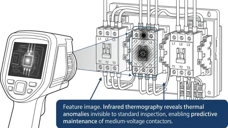
– Elevated operating temperatures: Thermal imaging showing abnormal heating indicates potential current rating mismatch
– Operation counter discrepancies: If recorded operations significantly exceed expected duty, re-evaluate application
– Timing drift: Changes in close/open timing may indicate mechanical wear from excessive duty
Controlled switching (point-on-wave switching) times circuit breaker closing to optimal voltage phase angles, minimizing inrush current magnitude. For three-phase transformers, the controller sequences the closing of each phase to achieve optimal flux conditions. Modern controllers achieve closing accuracy within ±1ms, reducing transformer inrush to 1-2 times rated current versus 8-12 times for uncontrolled closing. This dramatically extends transformer and circuit breaker life, with payback periods typically under two years for frequently-switched transformers.
Matching switching equipment to application duty requirements represents one of the most consequential decisions in MV system design. The consequences of misapplication range from accelerated equipment wear and increased maintenance costs to catastrophic failures and extended outages.
Essential principles for correct duty matching:
Never assume interchangeability: Motor, transformer, and capacitor switching impose fundamentally different stresses requiring specifically-rated equipment
Calculate before specifying: Perform inrush calculations for every application rather than relying on rules of thumb
Consider lifecycle operations: Switching frequency determines whether circuit breakers or contactors provide optimal lifecycle cost
Apply appropriate standards: IEC 62271 and IEEE C37 series standards provide specific test criteria for each application type
Document thoroughly: Maintain calculation records and equipment specifications to ensure correct replacement in the future
By systematically applying the decision framework presented in this article, engineers can confidently select switching equipment that will provide reliable service throughout its intended life, avoiding the costly consequences of application mismatch.
About the Author: This article draws on 18 years of field experience with medium-voltage switching applications across industrial, utility, and commercial sectors, including hands-on commissioning of over 200 MV switchgear installations and forensic analysis of numerous switching equipment failures.