Need Full Specifications?
Download our 2025 Product Catalog for detailed drawings and technical parameters of all switchgear components.
Get Catalog
Download our 2025 Product Catalog for detailed drawings and technical parameters of all switchgear components.
Get Catalog Download our 2025 Product Catalog for detailed drawings and technical parameters of all switchgear components.
Get Catalog
Vacuum contactors in capacitor banks, motor starters, and transformer feeders accumulate switching operations rapidly. A contactor energizing a capacitor bank twice daily reaches 730 operations annually. One controlling a frequently cycled motor might exceed 15,000 operations in the same period.
Measuring close/open time provides direct insight into contactor health before failure occurs. Each operation stresses the electromagnetic coil thermally and fatigues mechanical springs incrementally. The vacuum interrupter contacts erode microscopically with every current interruption. None of these degradation mechanisms announce themselves obviously—until the contactor fails to close during a critical switching command.
Field data consistently shows that timing parameters drift outside normal ranges 2,000–5,000 operations before functional failure. A contactor with a 40 ms baseline close time now measuring 65 ms communicates mechanical resistance or coil weakness—months before complete failure. Three parameters form the diagnostic foundation:
Contactor operation depends on coordinated interaction between electromagnetic force and mechanical movement. Understanding this relationship explains why timing measurements reveal specific fault conditions.
When DC voltage applies to the contactor coil, current rises according to the electromagnetic time constant τ = L/R, where coil inductance and resistance determine the current rise rate. The resulting magnetic flux pulls the armature against closing spring preload. Once flux overcomes spring force plus mechanical friction, the armature accelerates toward the magnetic pole face.
The closing spring assists armature travel during the final stroke, ensuring adequate contact force at touchdown. Contact wipe—additional travel after initial touch—compresses the contact springs and establishes reliable current-carrying interface. The complete sequence from coil energization to stable contact engagement defines close time.
Opening follows inverse principles. When coil voltage removes, magnetic flux decays as current dissipates through the coil circuit. The opening spring, compressed during closing, stores energy that drives contact separation once magnetic holding force drops sufficiently. Residual magnetism in the iron core can delay this transition—a common source of extended open time in DC-operated contactors.
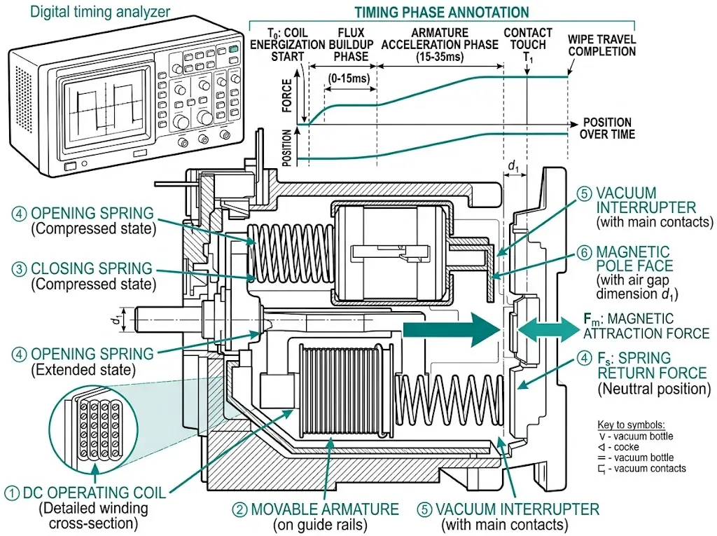
The mechanical system includes armature guides, pivot bearings, and linkage connections. Wear at any point increases friction, directly extending operate times. Spring fatigue reduces acceleration force, producing the same effect. Because timing reflects the combined health of electrical and mechanical subsystems, a single measurement captures information about multiple components simultaneously.
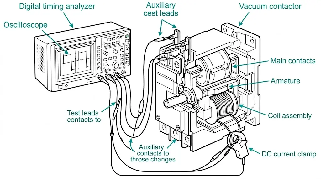
Accurate timing measurement requires instrumentation with adequate resolution and proper connection methodology.
| Equipment | Specification | Purpose |
|---|---|---|
| Digital timing analyzer | Resolution ≤100 µs, 4+ channels | Simultaneous capture of coil and contact states |
| DC current clamp | 0–10 A range, ≥10 kHz bandwidth | Coil current waveform acquisition |
| Variable DC power supply | 80–110% of rated coil voltage | Voltage sensitivity testing |
| Storage oscilloscope | ≥20 MS/s, 4 channels | Alternative to dedicated analyzer |
Dedicated timing analyzers from Omicron, Megger, or Doble include pre-configured contactor test routines. A quality oscilloscope with proper triggering yields equivalent data for facilities without specialized equipment.
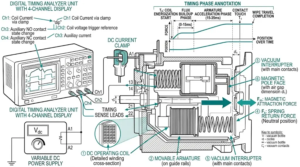
For JCZ vacuum contactor or CKG vacuum contactor series, reference manufacturer datasheets for model-specific connection points and baseline timing expectations.
[Expert Insight: Field Measurement Tips]
- Allow 30-second intervals between consecutive operations to prevent coil heating effects on timing
- Record ambient temperature—expect 5–10% timing increase at extremes (below −10°C or above +45°C)
- Test at 100% rated voltage first, then at 85% to verify pickup margin
- Compare pole-to-pole scatter; differences >3 ms indicate mechanical misalignment
Establishing clear thresholds enables consistent maintenance decisions across operating personnel and planning cycles.
| Parameter | Normal Range | Alarm Threshold | Action Required |
|---|---|---|---|
| Close time | 25–50 ms | >60 ms | >80 ms |
| Open time | 15–35 ms | >45 ms | >60 ms |
| Contact bounce | <2 ms | >3 ms | >5 ms |
| Pole scatter (close) | <3 ms | >5 ms | >8 ms |
| Pole scatter (open) | <2 ms | >4 ms | >6 ms |
These values apply at rated coil voltage and 20°C ambient temperature. Environmental compensation is necessary for extreme conditions: cold lubricant viscosity extends timing 10–25% at −20°C, while elevated coil resistance at +50°C produces similar effects.
Pole scatter—the difference between fastest and slowest pole operation—deserves particular attention. Scatter exceeding 5 ms during closing creates pre-arcing on the early-closing pole, accelerating contact erosion asymmetrically. The IEC 62271-106 standard addresses high-voltage contactor performance requirements.
The alarm threshold triggers investigation and trend monitoring. The action threshold demands maintenance intervention—either repair or replacement—before the next scheduled energization in critical applications.
Close time abnormalities fall into distinct patterns, each pointing toward specific root causes.
When close time exceeds 60 ms but coil inrush and steady-state current match historical values, the coil generates adequate magnetic force. Mechanical resistance delays armature travel. Investigate:
Extended close time combined with reduced coil current—both inrush and steady-state—indicates electrical degradation:
Measure coil resistance at 20°C and compare against specifications. Resistance deviation exceeding ±15% warrants coil replacement.
When initial close time falls within acceptable range but bounce duration exceeds 3 ms, contact force after touchdown is insufficient:
Each bounce event at load current erodes contact material equivalent to a normal closing operation. A vacuum contactor bouncing five times per close effectively ages five times faster than rated specification.
| Close Time Symptom | Coil Current Status | Probable Cause | Field Action |
|---|---|---|---|
| >60 ms | Normal | Mechanical binding | Inspect guides, check springs |
| >60 ms | Reduced 15–25% | Shorted turns or connections | Measure coil resistance |
| Normal | Bounce >3 ms | Spring fatigue | Replace contact springs |
Open time abnormalities indicate problems in the energy release portion of the operating cycle.
When open time exceeds 45 ms, the opening spring cannot accelerate contact separation quickly. Three mechanisms produce this condition:
Residual magnetism: The armature or magnetic core retains magnetic polarization after coil de-energization, maintaining holding force. DC-operated contactors are particularly susceptible. AC demagnetization of the magnetic circuit—applying diminishing AC voltage to a temporary winding—can restore normal operation.
Opening spring fatigue: Reduced spring force cannot overcome friction and residual magnetic attraction promptly. Measure spring free length against factory specification; replacement is straightforward if fatigue is confirmed.
Armature sticking: Contamination, corrosion, or surface damage creates adhesion between armature and pole faces. Cleaning and possible pole face resurfacing addresses this condition.
When open time varies significantly between consecutive operations—for example, 25 ms, 42 ms, 28 ms, 48 ms—investigate position-dependent or thermal-dependent conditions:
Execute 10–20 consecutive operations while monitoring timing. Purely random variation suggests mechanical looseness; progressive increase suggests thermal effects.
| Open Time Symptom | Probable Cause | Diagnostic Check | Field Action |
|---|---|---|---|
| >45 ms consistently | Residual magnetism | Coil current decay waveform | AC demagnetization |
| >45 ms consistently | Spring fatigue | Spring free length measurement | Replace opening spring |
| Highly variable | Mechanical looseness | Consecutive operation test | Tighten fasteners, inspect linkage |
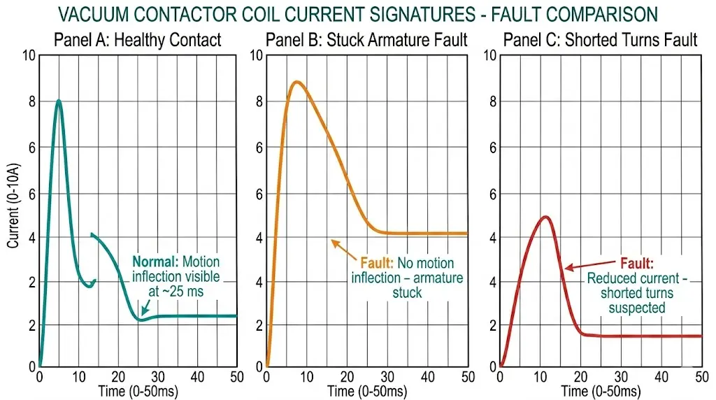
[Expert Insight: Coil Current Signature Diagnostics]
- Healthy DC coil current shows three phases: rapid inrush, motion inflection (brief current dip during armature travel), and steady-state plateau
- Missing motion inflection indicates stuck armature—mechanical investigation required
- Late-occurring inflection signals mechanical resistance delaying motion
- Excessive steady-state current (>110% of baseline) suggests shorted turns developing
Test frequency depends on operational duty cycle severity. High-operation applications require more frequent monitoring.
| Application | Annual Operations | Recommended Interval |
|---|---|---|
| Capacitor bank switching | 2,000–10,000 | Every 6 months |
| Frequent motor starting | 5,000–20,000 | Every 3–6 months |
| Transformer switching | 500–2,000 | Annually |
| Standby/backup duty | <500 | Every 2 years |
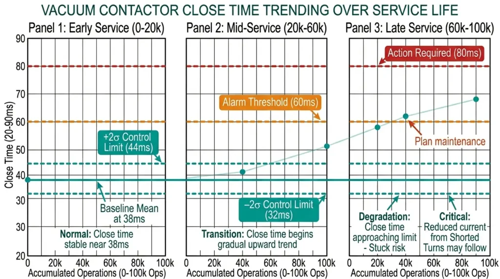
Plot timing values against accumulated operations—not calendar time. A contactor switching 50 times daily ages faster than one switching 5 times daily, regardless of installation date.
Statistical process control techniques apply effectively. Calculate mean and standard deviation from commissioning baseline using minimum 10 operations. Set control limits at ±3σ from mean. Investigate any single reading exceeding ±2σ. Initiate maintenance planning when the trend approaches manufacturer alarm threshold.
For facilities with multiple contactors in similar service, comparative analysis reveals outliers warranting investigation. Maintain spare coils and spring kits from switchgear parts inventory for units approaching end-of-life timing thresholds.
When timing analysis indicates end-of-life conditions, replacement planning benefits from suppliers providing documented timing specifications and spare parts availability. XBRELE provides engineered vacuum contactor solutions designed for extended service life and predictable maintenance intervals.
Our technical team supports proper selection matching application duty cycles, installation guidance ensuring correct baseline establishment, and spare parts provisioning for maintenance inventory. For capacitor switching, motor control, or transformer applications requiring vacuum contactors with documented performance characteristics, contact XBRELE’s vacuum contactor manufacturing team to discuss specifications.
Q1: What causes vacuum contactor close time to gradually increase over service life?
A1: Progressive close time increase typically results from contact erosion requiring longer armature travel, lubricant degradation increasing mechanical friction, or gradual spring fatigue reducing closing force—often these factors combine over high-operation service periods.
Q2: How can I distinguish between coil failure and mechanical binding using timing measurements?
A2: Monitor coil current waveform simultaneously with timing—normal current profile with extended timing indicates mechanical binding, while reduced current amplitude points to coil degradation such as shorted turns or high-resistance connections.
Q3: Does contact bounce affect vacuum contactor service life significantly?
A3: Excessive bounce (>3 ms) substantially accelerates contact erosion because each bounce event under load current erodes material comparable to a full switching operation, potentially reducing expected contact life by 50–80% in severe cases.
Q4: What ambient temperature range affects timing measurement accuracy?
A4: Timing measurements should ideally occur between 15–25°C; measurements below −10°C may show 10–25% timing extension due to lubricant viscosity, while temperatures above +45°C increase coil resistance and extend close time by similar margins.
Q5: How many test operations are needed to establish reliable baseline timing?
A5: A minimum of 10 consecutive operations at rated voltage and ambient temperature provides statistically meaningful baseline data; calculate mean and standard deviation to establish ±2σ investigation limits and ±3σ action limits.
Q6: Can abnormal timing in one pole indicate vacuum interrupter problems?
A6: Single-pole timing deviation while other poles remain normal typically indicates that pole’s vacuum interrupter mounting, individual contact spring, or pole-specific linkage—not shared components like the coil or main armature.
Q7: What is the relationship between pole scatter and contact erosion rate?
A7: Pole scatter exceeding 5 ms causes the early-closing pole to carry pre-arc current before other poles engage, concentrating erosion on that pole’s contacts and creating asymmetric wear patterns that progressively worsen scatter over time.
Authority reference: See IEC 62271-106 publication page for contactor standard framework.