Need Full Specifications?
Download our 2025 Product Catalog for detailed drawings and technical parameters of all switchgear components.
Get Catalog
Download our 2025 Product Catalog for detailed drawings and technical parameters of all switchgear components.
Get Catalog Download our 2025 Product Catalog for detailed drawings and technical parameters of all switchgear components.
Get Catalog
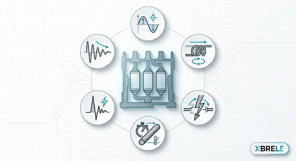
Decode key vacuum circuit breaker ratings including voltage class, interrupting current, BIL, short-time withstand, and duty cycle before RFQ submission.
Quick Takeaway (60 seconds)
A safe VCB selection is not “kV + A”. You must validate insulation (kV class + BIL/LIWV), fault duty (interrupting kA + Icw + making/close-latch), and transients (TRV/RRRV) against the short-circuit study at the breaker location and the project’s IEC/IEEE standard.
Rule of thumb: Treat short-circuit duty as a family — interrupting (kA) + short-time withstand (Icw) + making/close-latch. If your system is cable- or capacitor-heavy, add an explicit TRV check.
Medium-voltage systems don’t forgive rating mistakes. This guide explains vacuum circuit breaker (VCB) ratings in the way engineers actually use them: nameplate → short-circuit study → application checks.
If you want the fundamentals first, read:
What Is a Vacuum Circuit Breaker (VCB) and How Does It Work?
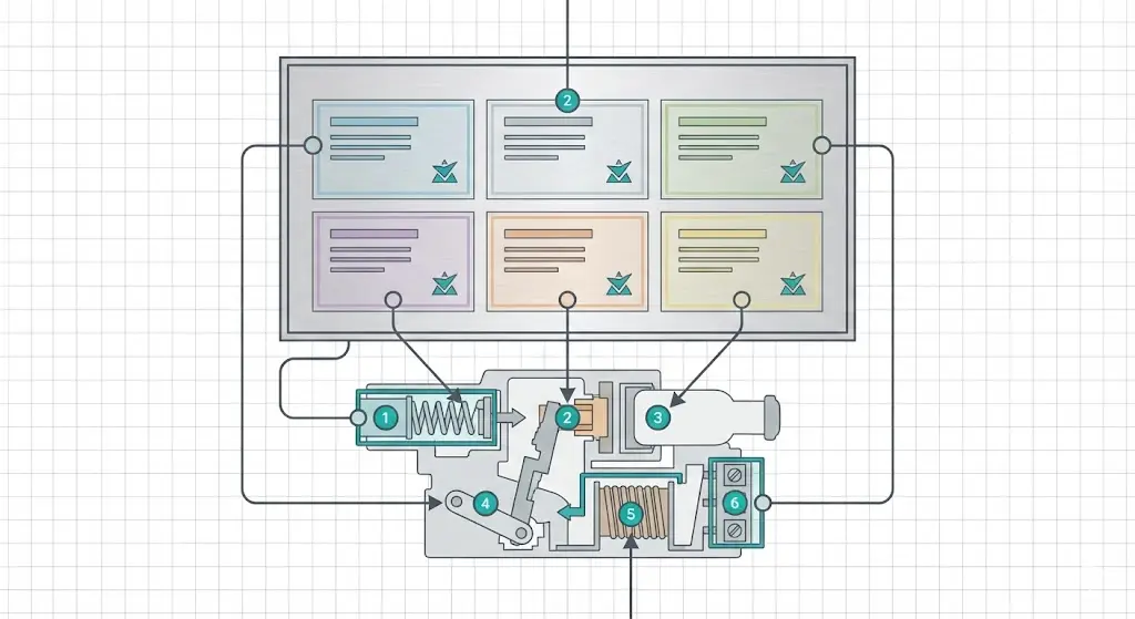
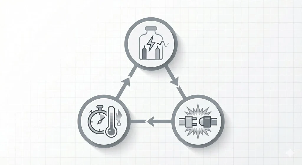
Most MV breaker issues are not caused by vacuum technology. They usually come from one of three mismatches:
This page is designed to prevent those errors.
Use this table to translate most VCB datasheets/nameplates quickly.
| Nameplate item | What it means in practice | Common symbols/labels |
|---|---|---|
| Rated voltage class | Equipment class (insulation/clearances) | kV, Ur, rated max voltage |
| Rated continuous current | Carry current within temp-rise limits | A, Ir |
| Short-circuit interrupting/breaking | Max fault current it can interrupt under test duty | kA, Isc |
| Lightning impulse withstand | Impulse insulation strength vs surges | BIL, LIWV (kVp) |
| TRV capability | Recovery voltage withstand after interruption (by test duties) | TRV / duty class |
| Short-time withstand | Survive fault current for time (selectivity delays) | Icw (1s/3s) |
| Making / close & latch | Close-on-fault robustness (peak forces) | making / close & latch |
Same capability, different labels. Use the project standard as your source of truth.
| Concept | Common IEC wording | Common IEEE wording | Practical note |
|---|---|---|---|
| Voltage class | Ur | Rated maximum voltage | Both define equipment class/insulation basis |
| Continuous current | Ir | Continuous current rating | Temperature rise / thermal design |
| Interrupting capability | Short-circuit breaking current | Interrupting rating | Confirm the same basis in your spec |
| Short-time withstand | Icw | Short-time withstand | Critical for selectivity delays |
| Close-on-fault robustness | making / peak withstand (vendor wording varies) | close & latch / making | Verify vendor datasheet |
| Impulse withstand | LIWV / BIL | BIL | Often written as BIL in both worlds |
| TRV capability | TRV per test duties | TRV per test duties | Application type matters (cables/caps) |
What it is: The voltage class that defines insulation clearances and withstand tests.
What to verify: nominal voltage vs “highest system voltage” assumptions in the project spec, and lineup withstand requirements.
If under-rated: partial discharge, flashover, insulation failure risk.
Context pages (optional):
What it is: Maximum continuous current within allowed temperature rise.
What experienced engineers check beyond Ir: ambient temperature, cubicle ventilation, sustained duty cycle, harmonic-heavy loads, hotspot connections.
If under-rated: chronic heating → higher contact resistance → accelerated wear.
What it is: Maximum fault current the breaker can interrupt under defined test duties.
Selection rule: Use short-circuit study results at the breaker location, not only bus fault values.
If under-rated: unsafe interruption, severe equipment damage risk.
What it is: Fault current the equipment can withstand for a defined time (often 1s or 3s).
Why it matters: Coordination delays mean upstream equipment must survive fault stress before clearing.
If under-rated: damage can occur before trip, or selectivity becomes unsafe.
What it is: The ability to survive close-on-fault peak forces (often the worst mechanical stress case).
Why it matters: In high X/R networks, peak electrodynamic forces can be the limiting case.
If under-rated: mechanical/contact damage, bounce, reduced life.
Practical framing that prevents mistakes:
Short-circuit family = interrupting (kA) + short-time withstand (Icw) + making/close-latch
What it is: Lightning impulse withstand strength in kVp (impulse insulation margin).
What to check: project BIL requirement, arrester assumptions and location, overhead exposure vs cable-fed network, lineup insulation coordination (bus, terminations, CT/PT).
If under-rated: impulse puncture or latent insulation damage.
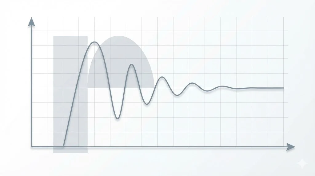
What it is: Recovery voltage across contacts immediately after interruption; severity depends on magnitude and RRRV.
Why it matters: Cable-heavy feeders and capacitor switching can create harsher recovery stress conditions.
TRV risk screener (fast): If “yes” to 2+, TRV should be an explicit check item:
1) long MV cable runs
2) capacitor bank switching (especially frequent/back-to-back)
3) frequent transformer switching/energization
4) mixed overhead + long cable network / resonance concerns
5) restrike history or unexplained insulation stress
For arc physics context, see:
What Is a Vacuum Interrupter (VI) and How Does It Work?
| Rating | Prevents | Typical wrong-selection outcome |
|---|---|---|
| kV / Ur | insulation stress at operating voltage | PD, flashover |
| A / Ir | overheating in service | hotspots, accelerated wear |
| kA / Isc | inability to interrupt faults | severe damage/outage |
| Icw | damage during delayed clearing | damage before trip / selectivity loss |
| Making / close-latch | close-on-fault peak forces | mechanical/contact damage |
| BIL / LIWV | impulse surge stress | insulation puncture/latent failure |
| TRV | post-interruption transient stress | restrike, overvoltage |
This stays concise here (a full field-by-field guide can be a separate long-tail post later).
Step 1 — Voltage class (Ur/kV): match to project class and withstand requirements.
Step 2 — BIL/LIWV (kVp): confirm impulse withstand meets insulation coordination assumptions.
Step 3 — Ir (A): confirm continuous current with margin for ambient/enclosure/duty cycle.
Step 4 — Interrupting (kA): confirm rating exceeds fault current at installation point.
Step 5 — Icw (1s/3s): confirm withstand time aligns with coordination clearing assumptions.
Step 6 — Making/close & latch (if required): verify close-on-fault robustness when specified.
Step 7 — TRV flag: for cable/cap/transformer-heavy switching, confirm switching duty/TRV suitability.
Study-first checklist you can defend in a design review and a failure investigation.
1) Confirm kV class + BIL (insulation coordination)
2) Size Ir with thermal margin
3) Use short-circuit study at installation point: kA + Icw + making/close-latch (as required)
4) TRV/switching duty sanity check for cable/cap/transformer-heavy systems
5) Verify duty/endurance if switching is frequent
Optional context links:
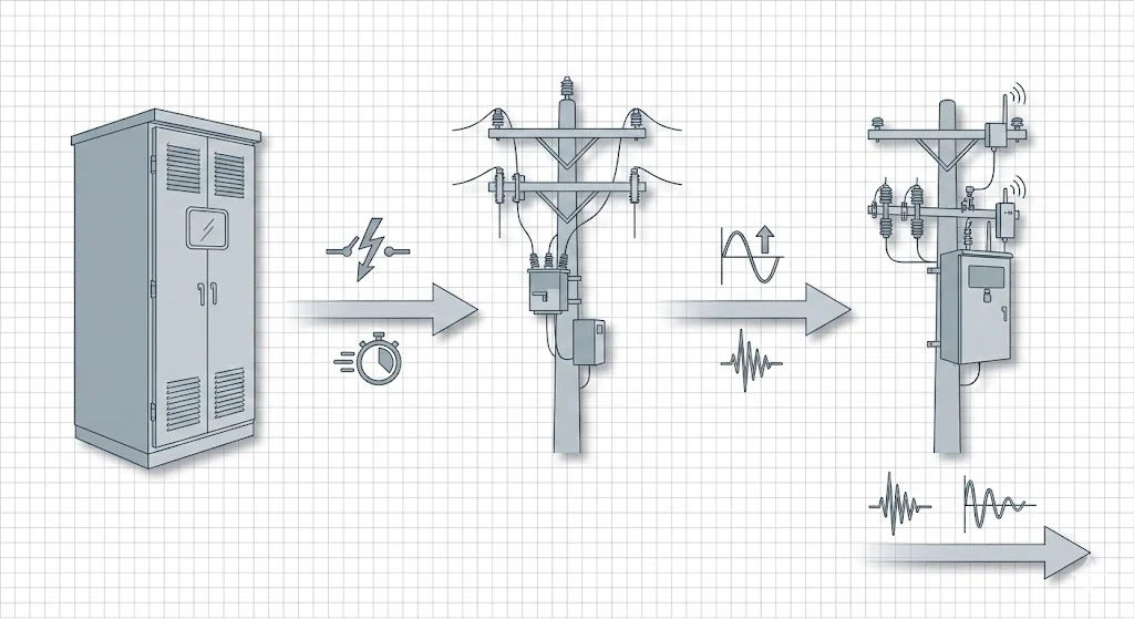
System: 11 kV plant distribution (commonly using 12 kV class equipment)
Continuous load: 980 A sustained → choose 1250 A for thermal margin
Fault at breaker location: 26 kA sym RMS → choose 31.5 kA interrupting
Coordination: intentional delay approaching ~1s possible → confirm Icw meets required duration
Insulation: match required BIL and confirm arrester assumptions
Network: cable-heavy + switched capacitor bank → TRV risk flagged → verify switching duty/TRV suitability
1) selecting by feeder nickname instead of equipment class + withstand levels
2) running Ir at the edge in hot rooms or dense cubicles
3) using bus fault values everywhere instead of location-specific fault current
4) ignoring Icw, then discovering selectivity isn’t safe
5) treating BIL as a formality while arrester assumptions differ
6) ignoring TRV in cable/cap-heavy networks, then chasing restrike symptoms
If you’re unsure whether you need a breaker or a contactor, read:
Is 12 kV class correct for an 11 kV system?
Often yes. Use the project equipment class and withstand requirements, not the feeder nickname.
What’s the difference between kA interrupting and Icw?
kA is what the breaker can interrupt; Icw is what it can withstand for time during coordination delay.
What does “close & latch” mean?
Close-on-fault robustness: ability to survive peak forces and remain latched.
Can a breaker meet kA rating but still restrike?
Yes. TRV/RRRV can cause restrike in cable/capacitor-heavy switching conditions.