முழு விவரக்குறிப்புகள் வேண்டுமா?
அனைத்து சுவிட்ச்கியர் பாகங்களின் விரிவான வரைபடங்கள் மற்றும் தொழில்நுட்ப அளவுருக்களுக்கு, எங்கள் 2025 தயாரிப்புப் பட்டியலைப் பதிவிறக்கவும்.
பட்டியல் பெறுக
அனைத்து சுவிட்ச்கியர் பாகங்களின் விரிவான வரைபடங்கள் மற்றும் தொழில்நுட்ப அளவுருக்களுக்கு, எங்கள் 2025 தயாரிப்புப் பட்டியலைப் பதிவிறக்கவும்.
பட்டியல் பெறுக அனைத்து சுவிட்ச்கியர் பாகங்களின் விரிவான வரைபடங்கள் மற்றும் தொழில்நுட்ப அளவுருக்களுக்கு, எங்கள் 2025 தயாரிப்புப் பட்டியலைப் பதிவிறக்கவும்.
பட்டியல் பெறுக

Control custom epoxy insulator development from drawing freeze to tooling review and first-article approval, with interface checks, evidence and change control.
Three things have to agree before a custom epoxy insulator goes into repeat production: the function the part performs inside the assembly, the controlled drawing that expresses that function in measurable terms, and the evidence that a part made by the intended production route meets that drawing. An incomplete agreement can hide an insert depth never referenced to a datum, a mould split line on a critical seating face, or a sample approved on dimensions alone.
A custom epoxy insulator is not a shape. It is a load path, a dielectric path and two or more mechanical interfaces sharing one cast body. Until those three are described separately and then tied together on one controlled drawing, a supplier can only quote a silhouette, and a buyer can only inspect a silhouette.
Start by naming what the part actually does. Three families dominate indoor switchgear work, and they are frozen differently.
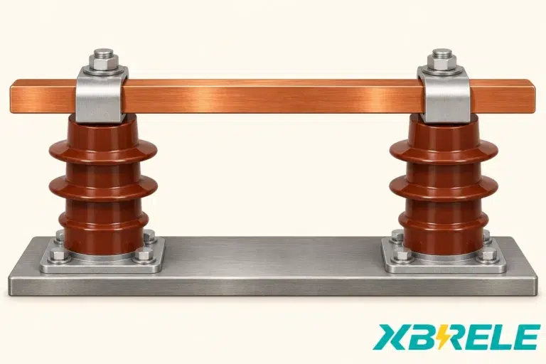
A mechanical post insulator holds a live conductor at a defined distance from earth and carries the mechanical reactions that come with it: the static weight of a busbar or contact assembly, the cantilever bending from connection forces, and the dynamic loads from short-circuit current. Its governing features are the two end interfaces, the bending stiffness of the body, and the creepage path across its surface. If the assembly restrains thermal movement, differential expansion can also load the post; the clamp and support arrangement determines that reaction.
A பூசணி insulates a conductor as it passes through a panel or enclosure wall. A தொடர்புப் பெட்டி encloses a stationary contact interface. Both need their actual conductor, mating and mounting geometry defined. Their governing features include the conductor’s position inside the resin, the wall thickness between conductor and earthed surfaces, the interface to the panel, and the geometry of the contact seat.
A கொள்ளளவு உணரி is a post or bushing body with an embedded electrode that forms a defined capacitance against the high-voltage conductor. Its governing feature is the position and area of that electrode, because those set the capacitance value and, more importantly, its stability across temperature and life.
All three are vulnerable to a drawing that fixes only the outer envelope and leaves the interior and interfaces open to interpretation.

A sample shell or a single overall height therefore cannot establish the complete function. What freezes function is the collected set of boundary conditions:
Installed context changes the answer. A post used vertically as a standoff carries a different bending moment from the same nominal post used horizontally as a cantilever, and the creepage surface collects contamination differently in each position. Two projects can specify “a 12 kV epoxy post, 140 mm tall” and need genuinely different parts.
A drawing that can be accepted or rejected without argument has a small number of specific properties. It names one revision. It measures from stated references. It ties every tolerance to a consequence. It says what may not be changed.
| Drawing field | What it must state | What goes wrong when it is left open |
|---|---|---|
| Part and revision identity | Unique part number, drawing number, revision letter, and the assembly the part belongs to | Two revisions circulate; the supplier tools one, the buyer inspects the other |
| Units and datum scheme | Units, projection convention, primary mounting face as datum A, insert axis as datum B, and which features are measured from them | Dimensions taken from different local faces cannot detect tilt or drift |
| Insert definition | Thread standard and size, usable thread depth, position relative to the datums, orientation, insert material and plating, retention method | A shorter usable depth passes an overall height check and still fails assembly |
| Mounting and mating faces | Flatness and parallelism to datum, contact area, and which surface defects are not permitted on the seating face | Flash or a dished face tilts the bracket and loads the insert in bending |
| Conductor and earth interfaces | Where the live conductor terminates, where earth is bonded, and which surfaces must be free of resin flash or coating | Interference fits or a resistive earth path discovered at assembly |
| Dielectric body | Minimum wall between conductor and earth, profile of sheds, and the exact two points between which creepage and clearance are measured | A creepage figure measured between the wrong endpoints certifies nothing |
| Material identity and change restriction | Resin system family, filler or aggregate class, colour, and an explicit statement that substitution requires written approval | A functionally different material arrives inside a passing dimensional report |
| Markings | What must be legible, where it goes, and by what method | Traceability is lost after installation |
| Tolerances linked to function | Each tolerance traceable to what it protects: fit, clamping, dielectric margin, sensor capacitance | Uniform blanket tolerances that are tight where irrelevant and loose where critical |
| Defect acceptance zones | Which zones are cosmetic, which are dielectric, which are sealing or mating | Cosmetic criteria applied to a dielectric surface, or the reverse |
The datum scheme is where most drawings quietly fail. Two examples show why the numbers on a drawing are less important than the references they hang from.
First conditional case — axial stack. Suppose the post has an insert at each end, each insert positioned by a depth tolerance from its own end face, and the assembly clamps a bracket, a washer and a busbar between them. If the insert depth range at the top, the bracket thickness range and the washer range together consume more of the fastener’s free thread than the design intended, the joint will not develop its clamp load even though every individual dimension is in tolerance. The fix is not a tighter insert tolerance in isolation; it is to define the required thread engagement and then distribute tolerance across the stack deliberately, or to reference both inserts to a common datum so the stack is visible.
Second conditional case — angular stack. Suppose both inserts are positioned correctly along the axis but their coaxiality to datum B is unspecified, because each was dimensioned from its own local face. A rigid busbar that fixes both ends of two posts will then pull the posts into alignment on assembly, bending the resin around the inserts. Nothing measured on the bench shows a problem; the part cracks in service, or the insert pulls out after thermal cycling. Here the missing callout is a geometric control relative to a common axis, and no amount of tightening on length will substitute for it.
Notice that neither case produces a universal number. The acceptable positional tolerance is whatever the mating part’s free play and the dielectric wall can absorb, and that figure comes from the assembly, not from a default table.
Freeze the drawing by fixing four things on paper before the mould is cut:

Tooling review is not a courtesy to the supplier. It is the buyer’s opportunity to see, before steel is cut, where the manufacturing method will struggle to deliver what the drawing asks for.
Five things belong in the review.
Mould split and demould direction. Every external shed, rib and undercut determines where the two mould halves part. The split line must land somewhere harmless. A split line or residual flash on a critical seating or dielectric surface needs an agreed location, finish and acceptance criterion; its consequence depends on the assembled geometry. Moving the split is cheap before the tool exists and expensive after.
Insert location and retention. Threaded inserts must be held by locators or pins at a defined position during casting and cure. They drift for understandable reasons: differential thermal expansion between the steel locator and the brass insert, uneven support allowing the insert to move under fill pressure, and resin shrinkage pulling the insert as the body contracts. A locator that is itself worn, or that depends on the operator seating the insert by hand, converts a drawing tolerance into a process variable.
Gate, vent and access. Gate position decides where the flow front travels and where air is finally pushed. Poor venting can leave internal voids. A void can become a partial-discharge site when its local electrical stress is sufficient, so internal quality is a different question from cosmetic appearance. Access also matters: whether inserts are loaded into the tool before closing or pressed in afterwards changes both the part and the cycle.
Thick-to-thin transitions. Filled epoxy systems shrink during cure. Differences in section thickness, temperature and restraint can produce uneven curing and shrinkage, with risks of stress, sink or voids near a heavy boss and thin wall transition. This is a geometry problem visible in the tool review, not a defect to be sorted at inspection.
Steel dimensions versus part dimensions. The tool is not cut to the drawing. It is cut to a set of dimensions that, at a defined material state and a defined cure cycle, will yield the drawing. That difference is the moulder’s compensation, and it depends on the resin system, the filler loading, the wall distribution, the volume fraction of inserts, the gating and the cure profile as they occur in that cavity. Writing an arbitrary shrinkage percentage onto the buyer’s drawing does not transfer that responsibility in a useful way — it transfers a number the buyer cannot own, while the decision remains with the process.
The reason a material name is not enough is visible in primary processing guidance. The Huntsman CY 228-2 / HY 918-1 data sheet, which describes an indoor electrical-insulation resin system that may be processed by APG or conventional vacuum casting, connects thorough mixing and filler wetting with shrinkage, internal stress and partial-discharge behaviour. It also notes that cure completion should be established by measurement on the object or by glass transition temperature, and that a changed gel or cure cycle can alter crosslinking and Tg. That is the mechanism in one sentence: the drawing fixes the result, the process produces it, and the same approved resin can yield different internal quality under a different cycle. (This is a named resin example illustrating process sensitivity; it is not a statement about which resin any particular supplier uses.)

First-article approval is an agreement, not a form. It means the buyer and supplier have agreed, before the sample is made, that this specific evidence — produced on a sample made by the intended production route — will demonstrate conformity to the frozen drawing. “Intended production route” is the operative phrase: the same tool, the same cavity, the same insert type and position, the same material lot family, the same cure cycle, and the same post-cure if one is specified. A sample from a different route is a prototype, and approving a prototype tells you about the design, not about production.
This is not the aerospace first-article format by default. AS9102 is a specific industry requirement with its own forms; if a programme is not subject to it, importing it adds paperwork without adding insight. Nor is first-article approval type approval — the two answer different questions and neither substitutes for the other.

| சாட்சி | The question it answers | What it does not establish |
|---|---|---|
| Dimensional report with stated datum and method | Does this sample match the frozen geometry at the defined references? | Whether internal voids or cure gradients exist |
| Material and lot identity | Was the specified resin system and lot used? | That cure is complete |
| Visual criteria on agreed functional zones | Are the surfaces that matter free of the defects that matter? | Sub-surface condition |
| Insert, fit and load verification defined by the design | Does the joint close, clamp and carry its defined load? | Long-term creep of resin under sustained load |
| Electrical test to an agreed plan | Does this sample hold the specified voltage with the specified discharge behaviour, at the specified sensitivity? | That the next cavity behaves the same |
| Sample and process traceability | Was it made on the intended tool, cavity and cycle revision? | Anything about performance on its own |
Two standard scopes are commonly cited at this point, and both need their boundaries stated precisely.
IEC 60660:1999 addresses tests on indoor organic post insulators operating in air at atmospheric pressure, on AC above 1000 V and below 300 kV, at frequencies up to 100 Hz, excluding composite insulators. That places an indoor epoxy post of the relevant voltage class inside the standard’s family when test methods are being selected. It does not mean the standard’s clause set is the right one for a contact box or a bushing, and its public scope does not establish the acceptance values for the proposed part. Select the applicable tests and criteria from the full relevant requirements and the agreed product or project specification. Citing a standard edition is also not a statement that any product complies with it; compliance is a claim supported by test evidence scoped to that product, and current compliance is not inferred from a historical reference.
IEC 60270:2025 covers charge-based partial-discharge measurement on apparatus, components and systems under AC up to 500 Hz or DC, and describes measured quantities, test circuits, calibration, measurement methods, procedural guidance and interference discrimination. It defines எப்படி to measure, not what passes. An apparatus-specific acceptance level has to come from the relevant product or project specification; the standard’s scope is not a universal picocoulomb threshold. A certificate line reading “PD tested to IEC 60270” is therefore incomplete unless it also states the test voltage, the duration, the measured quantity, the calibration basis and the acceptance limit that was applied.
These distinctions matter because the four evidence types are routinely confused. First-article inspection compares one sample against the frozen drawing. வகைச் சோதனைகள் verify the relevant design characteristics against a standard or specification; changes may require renewed assessment. வழக்கமான சோதனைகள் apply to each unit where the applicable product requirements call for them. Factory acceptance tests are the agreed acceptance checks for supplied equipment and may include buyer witnessing, document review or other agreed evidence. The test plan should distinguish these from any separate lot-sampling inspections.
One further point deserves to be written into the plan rather than discovered later: a single approved sample does not prove repeatability. One cavity, one lot, one operator and one cure cycle describe a point, not a distribution. If repeatability matters — and for a dielectric part with an embedded electrode it usually does — the first-article plan should say how the second and third samples are used and what varies between them.
A deviation is only manageable if it is written against the exact requirement it violates. “Insert depth out of tolerance” is not a record; “usable thread depth measured at 0.6 mm below the minimum stated in drawing note 4, on sample S-01, cavity 2” is a record, because it identifies the requirement, the measurement and the object.
Each deviation needs a disposition from a named authority: use-as-is with a technical justification, rework, repair to an approved method, scrap, or a drawing revision if the departure is to become the new requirement. An approved deviation must state its scope: the named sample, lot, quantity or period and conditions. Conceding a specific sample does not edit the drawing or automatically license the next shipment. If the concession reveals that the requirement was wrong, the correct action is a revision with its own review — not an accumulating pile of informal waivers.
Rework and retest plans should be accepted before anyone touches the part. Two practices cause disproportionate harm on cast epoxy dielectric parts: filling a visible crack or void with a cosmetic compound, and drilling or tapping an insert location after cure. Both change a dielectric body in ways that no surface inspection recovers, and both should require an explicitly approved method or be refused outright.
Changes propagate, and the propagation is what an impact review exists to map. Any change to insert geometry, material system, tool, cure cycle or cavity count should trigger a recorded assessment of four things:
The outcome should be proportionate. Two conditional cases show the range.
Case one: exterior identical, insert different. A second article is produced to the same outer profile but with a reduced usable thread depth, because the insert locator was altered between tool builds. Every external dimension passes. The part still fails at assembly, because the fastener bottoms out before the bracket is clamped. The correct disposition is a nonconformance against the insert note, an insert-position measurement capability check on the tool, and re-approval of the insert interface — with any further tests selected after assessing whether changed insert geometry or position also affects mechanical strength, wall thickness or electric-field conditions.
Case two: exterior identical, process different. A later gate or cure change leaves the outer dimensions untouched and produces parts that pass the dimensional report. The interior may now contain voids or a different degree of cure, which is precisely the region the dimensional report does not see. Here the impact review must address cure state and internal dielectric quality as well as possible mechanical effects. Select electrical, material, mechanical, dimensional or internal-inspection checks according to the affected characteristics and applicable requirements. External dimensional conformity alone cannot close the change.
The failure mode to avoid in both directions is the all-or-nothing response — either retesting everything, which quietly discourages disclosing changes, or retesting nothing, which lets a process change travel unnoticed inside a compliant envelope.
The four hold points below turn the sequence into something a purchasing team can enforce without reading the drawing itself. Each row has one owner, one set of inputs, one piece of evidence and one recorded decision.
| Hold point | உரிமையாளர் | Inputs required | Evidence produced | Decision recorded |
|---|---|---|---|---|
| HP1 — Drawing freeze | Design engineer, with buyer | Assembly context, mating parts, load and dielectric requirements, intended test specification | Frozen drawing at a named revision, with datum scheme, insert definition, material restriction and model/drawing precedence stated | Drawing approved and released for tooling; revision and date recorded |
| HP2 — Tooling review | Supplier process owner, with buyer’s engineer | Frozen drawing, insert specification, proposed mould layout, locator concept, gating and cure intent | Review record listing split lines, insert retention method, fill and vent approach, thick/thin risk areas, and agreed process compensation responsibility | Tool build authorised with the agreed review actions closed or listed as open with owners |
| HP3 — First article | Supplier quality, with buyer’s engineer | Frozen drawing, agreed evidence plan, sample from the intended production route | Dimensional report with datums and methods, material and lot identity, visual record on functional zones, fit and load verification, electrical results with test conditions and limits, sample and process traceability | Sample approved, conditionally approved against listed deviations, or rejected — with each deviation recorded |
| HP4 — Serial release | Buyer, with supplier quality | Approved first article, closed deviations, agreed routine test plan | Required routine test records and agreed lot-sampling records, marking and traceability confirmation, packing and documentation check | Repeat production released, with the routine test scope and shipment documentation fixed |
Four commercial conditions should be settled in the same document rather than left to the first shipment, because each one has a way of becoming a dispute:
Template clauses with blanks are safer than invented service terms, because they force the parties to state their own position: for example, “Tooling remains the property of __; maintenance responsibility and refurbishment triggers are defined in _; any refurbishment requires re-verification per ___.” That wording makes the gap visible instead of hiding it behind a standard phrase.
For a part that is an epoxy post insulator or a capacitive sensor, the starting point is the existing post-insulator and sensor range at XBRELE epoxy post insulators and capacitive sensors, where custom mould design is offered as a service enquiry rather than a catalogue item. The enquiry works best when it arrives with the drawing, the mating parts and the intended acceptance plan together; the broader switchgear parts RFQ template is a reasonable checklist for the surrounding commercial information. When the drawing is frozen and the evidence plan drafted, send both through the XBRELE contact route and ask directly whether the proposed geometry, insert arrangement and test plan can be produced and verified — that question, asked early, is cheaper than asking it after tooling.
No. A geometry-only CAD file may omit datums, usable thread depth, critical faces, material, tolerances and revision control. A controlled model with agreed product manufacturing information can carry such requirements, but its authority and revision status must be explicit. For a package using both 2D drawing and 3D model, define their precedence and include the inspection and test requirements.
No — they answer different questions. First-article approval shows that one sample made by the intended production route matches the frozen drawing. Type tests qualify the design against a standard or project specification, typically once per design, and their results describe the design’s capability rather than a particular unit’s conformity. A programme may legitimately need both, sequentially: type testing to establish the design, then first-article approval to confirm that production makes what was type tested. Where a standard such as IEC 60660:1999 is cited, keep in mind that its scope defines the family of tests for indoor organic post insulators in the stated voltage and frequency range; its public scope is insufficient to establish the acceptance criteria for a given custom part.
No. A single sample demonstrates that the route can produce a conforming part, not that it reliably does. Batch-to-batch variation enters through material lot differences, insert lot and seating, tool wear, cure cycle drift and cavity-to-cavity differences. That is why required routine tests and agreed sampling inspections, marking and traceability, and defined tool-maintenance triggers belong in the release conditions rather than in the first-article record. If the part’s dielectric function is sensitive to internal quality, the plan should also state how the routine electrical check is performed and what acceptance limit applies, since a partial-discharge measurement method such as IEC 60270:2025 describes how to measure and calibrate but does not define a pass level.
Reapproval is triggered by change, and the scope should be proportional to what the change touches. Any change to insert geometry or position, resin system or filler class, tool or cavity count, gating, or cure cycle warrants a recorded impact review covering the dielectric path, the mechanical path, the dimensional interface and, for a sensor, the capacitance. A locator change may affect fit, mechanical loading or internal field geometry; a gate or cure change may alter internal quality while leaving dimensions intact. Choose the re-verification scope from those consequences, rather than assuming an exterior match limits the review to dimensions. Tool refurbishment, a shift to a new production site, or a supplier-initiated material substitution fall under the same rule.
Sometimes, and it is worth checking before committing to a custom design. If an existing post insulator or contact box already matches the required voltage class, installed orientation, insert threads and mounting interface, a standard part may avoid a new mould and custom tooling review. The selected part revision, assembly interfaces and applicable qualification evidence still need approval. The check is whether the interfaces truly match rather than merely resembling each other — thread, usable depth, seating face, conductor position and creepage path all have to line up with the actual assembly. Where the difference is limited to one interface, modifying the mating bracket is frequently cheaper than a new mould, and a change to the dielectric body or an embedded electrode needs a separate design and qualification assessment.