முழு விவரக்குறிப்புகள் வேண்டுமா?
அனைத்து சுவிட்ச்கியர் பாகங்களின் விரிவான வரைபடங்கள் மற்றும் தொழில்நுட்ப அளவுருக்களுக்கு, எங்கள் 2025 தயாரிப்புப் பட்டியலைப் பதிவிறக்கவும்.
பட்டியல் பெறுகஅனைத்து சுவிட்ச்கியர் பாகங்களின் விரிவான வரைபடங்கள் மற்றும் தொழில்நுட்ப அளவுருக்களுக்கு, எங்கள் 2025 தயாரிப்புப் பட்டியலைப் பதிவிறக்கவும்.
பட்டியல் பெறுகஅனைத்து சுவிட்ச்கியர் பாகங்களின் விரிவான வரைபடங்கள் மற்றும் தொழில்நுட்ப அளவுருக்களுக்கு, எங்கள் 2025 தயாரிப்புப் பட்டியலைப் பதிவிறக்கவும்.
பட்டியல் பெறுக
நம்பகமான MV கட்டுப்பாட்டு வயரிங்கிற்காக, சுவிட்ச்ஜியர் டெர்மினல் பிளாக் பிராண்டுகள், மதிப்பீடுகள், பொருட்கள், சான்றிதழ்கள் மற்றும் நிறுவல் சோதனைகளை ஒப்பிடுக.
நான் நடுத்தர மின்னழுத்த ஸ்விட்ச்ஜியர் அமைப்புகளை வடிவமைத்து, அவற்றை ஆணையிட்டு வரும் எனது இருபது மூன்று ஆண்டுகளில், எண்ணற்ற பேனல் செயலிழப்புகளைக் கண்டிருக்கிறேன். அவை முதன்மை சுவிட்ச்சிங் சாதனங்களால் ஏற்படாமல், டெர்மினல் பிளாக்குகள், வயர் டக்டுகள், ஃபெரூல்கள் மற்றும் கட்டுப்பாட்டு வயரிங் துணைக்கருவிகள் போன்ற சிறிய பாகங்களால் ஏற்பட்டவை. இந்த பாகங்கள், ஒருவேளை மொத்த ஸ்விட்ச்ஜியர் செலவில் 2-5% மட்டுமே இருந்தாலும், அமைப்பின் நம்பகத்தன்மை, பராமரிப்புத் திறன் மற்றும் நீண்ட கால செயல்பாட்டுப் பாதுகாப்பு ஆகியவற்றை நேரடியாகப் பாதிக்கின்றன.
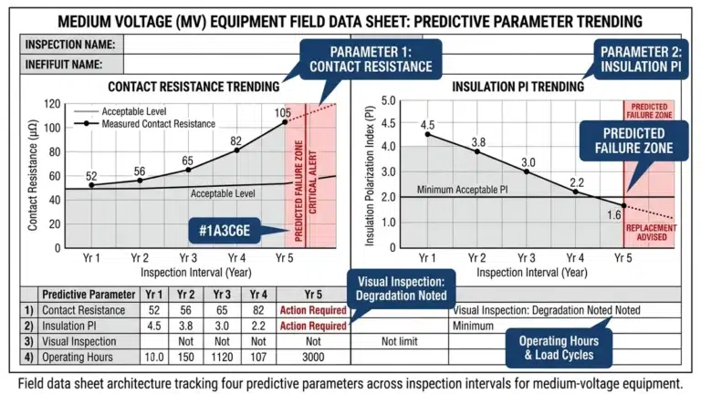
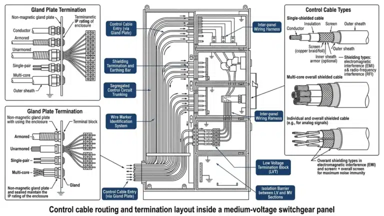
சுவிட்ச்ஜியரில் உள்ள நரம்பு இணைப்பு மையங்களாக டெர்மினல் பிளாக்குகள் செயல்படுகின்றன, அவை பாதுகாப்பு ரிலேக்கள், மீட்டரிங் அமைப்புகள், மோட்டார் ஆபரேட்டர்கள் மற்றும் தகவல் தொடர்பு வலையமைப்புகளை இணைக்கின்றன. தரம் குறைந்த ஒரு டெர்மினல் பிளாக், ஒரு முழு துணை மின்நிலையத்திலும் தொடர் தோல்விகளை ஏற்படுத்தக்கூடும். என் தொழில் வாழ்க்கையின் ஆரம்பத்திலேயே இந்த பாடத்தைக் கற்றுக்கொண்டேன், ஒரு பெட்ரோகெமிக்கல் ஆலையில் இருந்த 15kV சுவிட்ச்கியர் வரிசையில் கோடைகால வெப்ப அலைகளின் போது கட்டுப்பாட்டு மின்சுற்றுத் தோல்விகள் ஏற்பட்டன—நாங்கள் குறிப்பிட்டிருந்த சாதாரண டெர்மினல் பிளாக்குகளால், உறைக்குள் இருந்த 65°C சுற்றுப்புற வெப்பநிலையைத் தாங்க முடியவில்லை.
இந்த விரிவான வழிகாட்டி, பொறியாளர்கள், விவரக்குறிப்பாளர்கள் மற்றும் கொள்முதல் வல்லுநர்கள் உகந்த கட்டுப்பாட்டு வயரிங் கூறுகளைத் தேர்ந்தெடுக்க உதவுவதற்காக, நிஜ உலக நிறுவல் அனுபவம், உற்பத்தியாளர் தொழில்நுட்பத் தரவுகள் மற்றும் தொழில் தரநிலைகள் ஆகியவற்றிலிருந்து எடுக்கப்பட்டுள்ளது. நாங்கள் முன்னணி உற்பத்தியாளர்களை ஆராய்ந்து, தெளிவான தேர்வு அளவுகோல்களை நிறுவி, உங்கள் அடுத்த சுவிட்ச்கியர் திட்டத்தில் உடனடியாகப் பயன்படுத்தக்கூடிய நடைமுறை சரிபார்ப்புப் பட்டியல்களை வழங்குவோம்.
நடுத்தர மின்னழுத்த ஸ்விட்ச்ஜியர் கட்டுப்பாட்டுச் சுற்றுகள் பொதுவாக 24-250VDC அல்லது 120-240VAC-ல் செயல்படுகின்றன. இவை இந்த மின்னழுத்த நிலைகளுக்கு மதிப்பிடப்பட்ட கூறுகளைத் தேவைப்படுத்துவதோடு, MV சூழல்களில் உள்ள மின்காந்தத் தடையும் வெப்ப நிலைகளையும் தாங்கும் திறன் கொண்டிருக்க வேண்டும்.
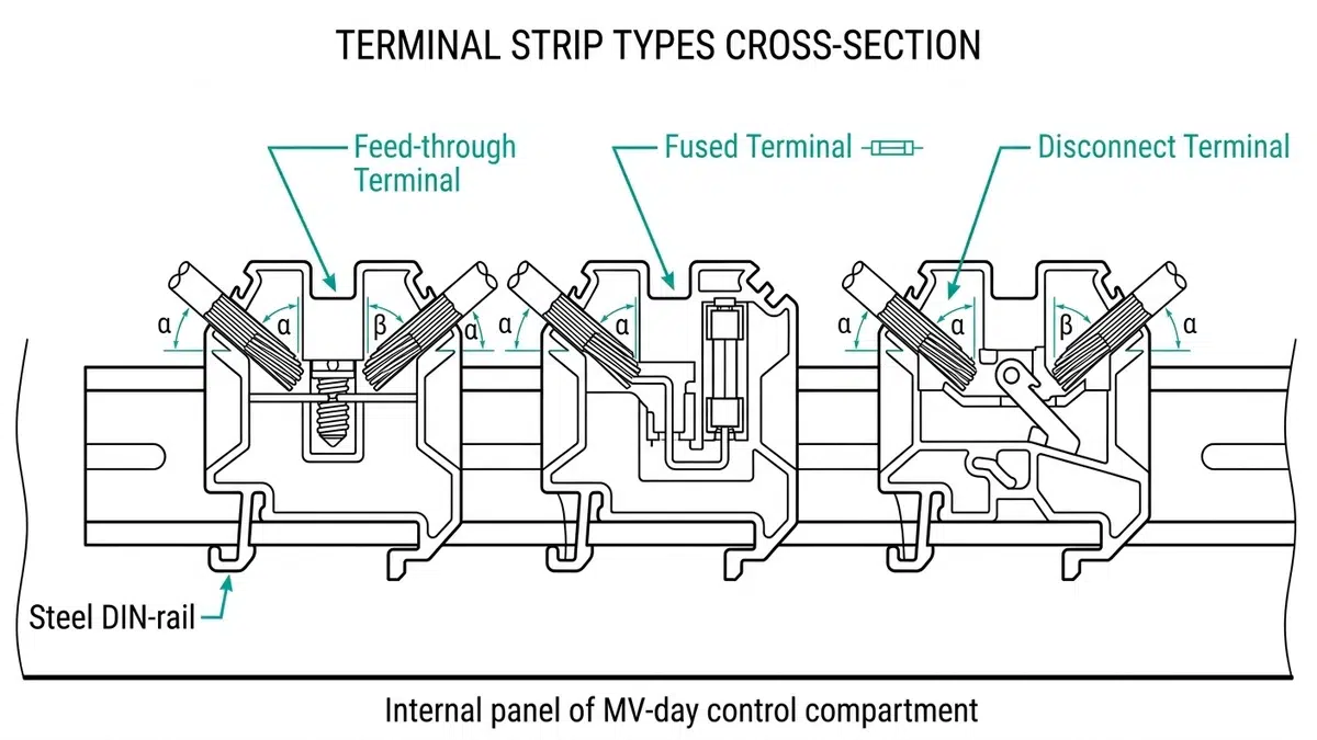
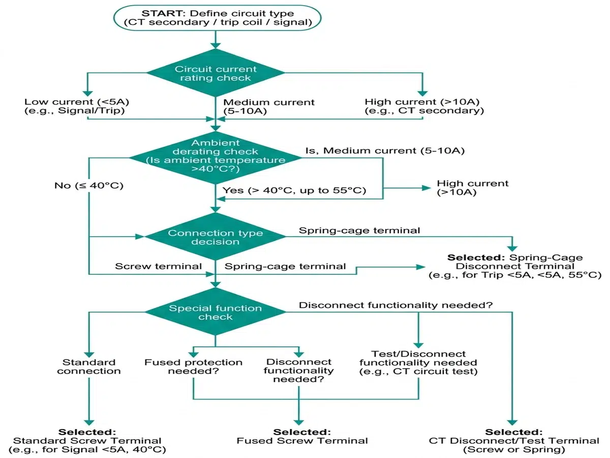
முனையடைப்புத் துண்டுகள் கட்டுப்பாட்டு வயரிங் அமைப்புகளின் அடித்தளத்தை உருவாக்குகின்றன. சுவிட்ச்கியர் பயன்பாடுகளுக்கு, நாங்கள் பொதுவாகக் குறிப்பிடுவது:
– ஊடுருவல் முனைகள் பொதுவான சிக்னல் மற்றும் மின்சார விநியோகத்திற்கு
– உருக்கிய முனையக் கட்டங்கள் CT மற்றும் PT இரண்டாம் நிலை சுற்றுகளைப் பாதுகாத்தல்
– துண்டிக்கப்பட்ட முனைகள் பராமரிப்பின் போது மின்சுற்றுத் துண்டித்தலை செயல்படுத்துதல்
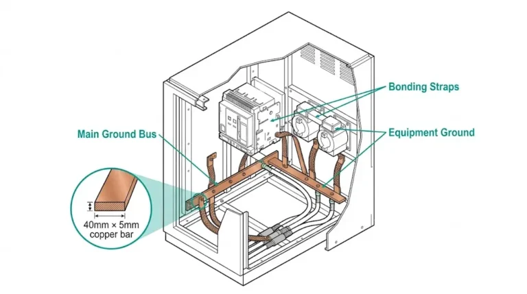
– நிலையூட்டல் முனைகள் சரியான பிணைப்பு மற்றும் பாதுகாப்பு மண் இணைப்பை உறுதி செய்தல்
– சென்சார்/செயலிழைப்பான் முனையங்கள் சிக்கல் தீர்க்கும் ஒருங்கிணைந்த LED சுட்டிகளுடன்
கம்பி மேலாண்மைக் கூறுகள் சேர்க்கவும்:
– துளைக்கப்பட்ட கம்பி குழாய் (பாண்டூட் பாணி அல்லது அதற்கு இணையான)
– சுருள் உறை மற்றும் பின்னப்பட்ட உறை
– கேபிள் டைகள் மற்றும் பொருத்தும் தளங்கள்
– குழாய் இணைப்பான்கள் மற்றும் திரவப் பிடிப்பு இணைப்பான்கள்
அதே கட்டுப்பாட்டு-பேனல் BOM மதிப்பாய்வில், தொழில்முறைக் கட்டுப்பாட்டுக் கூறுகள் தேர்வான் சுவிட்சுகள், சுட்டிக் காட்டும் விளக்குகள், துண்டிப்பான் கருவிகள் மற்றும் துணைத் தொடர்புகள் போன்றவை, முனையப் பலகைகள் மற்றும் கம்பி வழித்தடம் ஆகியவற்றுடன் சேர்த்துச் சரிபார்க்கப்பட வேண்டும், ஏனெனில் கம்பிவழி அமைப்பு மற்றும் இயக்குநர் இடைமுகத் தேர்வுகள் ஒன்றுக்கொன்று தாக்கத்தை ஏற்படுத்திக்கொள்கின்றன.
அடையாளம் மற்றும் குறியிடல் அமைப்புகள் உள்ளடக்கு:
– முன்பே அச்சிடப்பட்ட கம்பி குறியீடுகள்
– டெர்மினல் பிளாக் லேபிள்கள்
– கேபிள் டேக்குகள் மற்றும் ஃபெரூல்கள்
– லேசர் அச்சிடக்கூடிய லேபிளிங் அமைப்புகள்
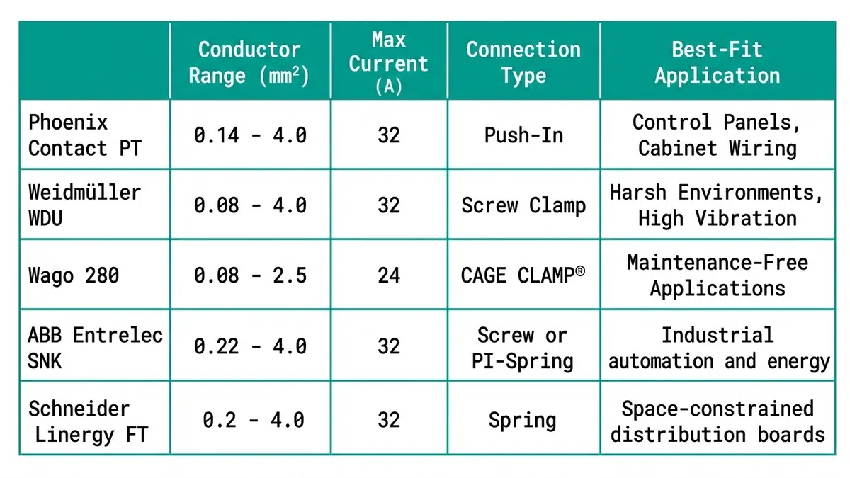
ஃபீனிக்ஸ் காண்டாக்ட் உலகளாவிய அளவில் சுவிட்ச்கியர் உற்பத்தியாளர்களிடையே ஒரு பிரீமியம் தேர்வாகத் தொடர்ந்து இடம்பிடித்துள்ளது. அவர்களின் CLIPLINE முழுமையான அமைப்பு வழங்குவன:
சமீபத்தில் ஒரு டேட்டா சென்டருக்காகச் செய்த 15kV சுவிட்ச்ஜியர் திட்டத்தில், நாங்கள் முழுவதும் ஃபீனிக்ஸ் காண்டாக்ட்டின் PTIO டிஸ்கனெக்ட் டெர்மினல்களைப் பயன்படுத்தினோம். கருவி தேவையற்ற புஷ்-இன் இணைப்பு, டெஸ்ட்/டிஸ்கனெக்ட் செயல்பாட்டுடன் சேர்ந்து, எங்கள் பேனல் வயரிங் நேரத்தை ஒரு வரிசைப் பிரிவிற்கு 18 மணி நேரத்திலிருந்து சுமார் 11 மணி நேரமாகக் குறைத்தது.
ஜெர்மன் பொறியியல் துல்லியம், வெய்ட்முல்லரின் டெர்மினல் பிளாக் தயாரிப்புகளை வரையறுக்கிறது. அவற்றின் கிளிப்பான் கனெக்ட் தொடர் பின்வருவனவற்றை வழங்குகிறது:
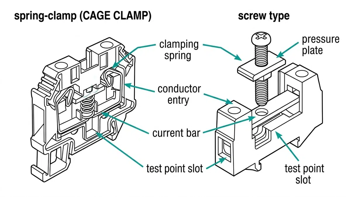
வாகோ, தங்களின் கேஜ் கிளாம்ப் ஸ்பிரிங் இணைப்புத் தொழில்நுட்பத்தின் மூலம் தொழில்துறையில் புரட்சியை ஏற்படுத்தியது. முக்கியத் தயாரிப்புகளில் அடங்குபவை:
ABB-யின் என்ட்ரெலெக் பிரிவு, சுவிட்ச்கியர் ஒருங்கிணைப்பிற்காக பிரத்யேகமாக வடிவமைக்கப்பட்ட டெர்மினல் பிளாக்குகளை வழங்குகிறது:
ராக்க்வெல் தளங்களில் தரப்படுத்தப்பட்ட வட அமெரிக்க சந்தைகள் மற்றும் வசதிகளுக்காக:
பாண்டூட் தங்களின்: மூலம் வட அமெரிக்காவின் வயர் டக்ட் சந்தையில் ஆதிக்கம் செலுத்துகிறது.
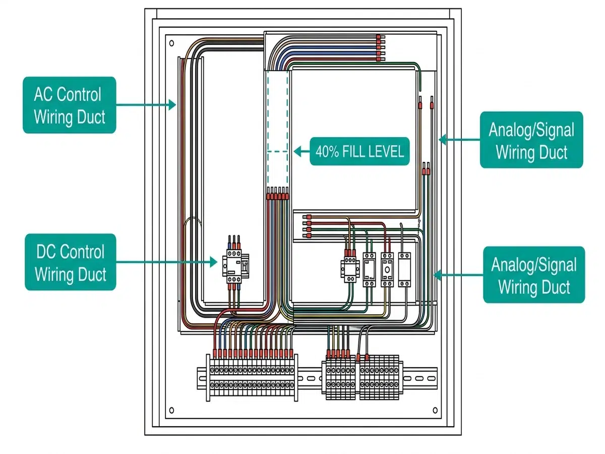
மீட்டரிங் அறைகளில் அனலாக் சிக்னல் வழித்தடத்திற்காக மட்டுமே நான் பாண்டூட் டைப் ஜி டக்டை (இறுக்கமான இடைவெளி, அகலமான விரல்) பிரத்தியேகமாகக் குறிப்பிட்டுள்ளேன்—இறுக்கமான இடைவெளிகள் தற்செயலாக வயர்களை வெளியே எடுப்பதைத் தடுக்கும் அதே வேளையில், அணுகலையும் பராமரிக்கின்றன.
ஹெல்லர்மேன்டைட்டன் பின்வருவனவற்றின் மூலம் சிறப்பான மதிப்பை வழங்குகிறது:
ஐரோப்பிய சுவிட்ச் கியர் உற்பத்தியாளர்கள் அடிக்கடி Iboco தயாரிப்புகளைப் பரிந்துரைக்கின்றனர்:
MV சுவிட்ச்ஜியர் கட்டுப்பாட்டு சுற்றுகளுக்கு டெர்மினல் பிளாக்குகளைக் குறிப்பிடும்போது, சரிபார்க்கவும்:
| அளவுரு | குறைந்தபட்சத் தேவை | பரிந்துரைக்கப்பட்ட விவரக்குறிப்பு |
|---|---|---|
| மதிப்பிடப்பட்ட மின்னழுத்தம் | 300V (UL) / 500V (IEC) | 600V (UL) / 800V (IEC) |
| மதிப்பிடப்பட்ட தற்போதைய | சுற்று அதிகபட்சம் × 1.25 | சுற்று அதிகபட்சம் × 1.5 |
| குறுசுற்று மதிப்பீடு | மேல்நிலைப் பாதுகாப்போடு ஒருங்கிணைத்தல் | மாட்ச் பிரேக்கர்/ஃபியூஸ் கடத்துதல் |
| நெருக்கடித் தாங்குதல் | குறைந்தது 2.5kV | நடுத்தர மின்னழுத்தப் பயன்பாடுகளுக்கு 4kV |
சுவிட்ச் கியர் சூழல்கள் தனித்துவமான சவால்களை முன்வைக்கின்றன:
வெப்பநிலை மதிப்பீடுகள் கணக்கில் எடுத்துக்கொள்ள வேண்டும்:
– சுற்றுப்புற வெப்பநிலைகள் (பெரும்பாலும் IEEE C37.20.2-இன் படி 40°C)
– உள் வெப்பநிலை உயர்வு (பொதுவாகக் கூடுதலாக 15-25°C)
– அருகிலுள்ள உபகரணங்களிலிருந்து வரும் வெப்பப் பங்களிப்பு
பாலைவன காலநிலையில் வெளிப்புற ஸ்விட்ச் கியருக்காக, நான் 105°C-ல் தொடர்ச்சியாக இயங்கக்கூடிய டெர்மினல்களைப் பரிந்துரைத்துள்ளேன்—ஏனெனில், 85°C என்ற சாதாரண மதிப்பீடுகள் 2-3 ஆண்டுகளுக்குள் இணைப்புத் தோல்விகளுக்கு வழிவகுக்கும்.
திர்ணக்கம் மற்றும் அதிர்ச்சி எதிர்ப்பு விஷயங்கள்:
– நில அதிர்வுப் பயன்பாடுகள் (IEEE 693 தகுதி)
– சுழலும் இயந்திரங்களுக்கு அருகிலுள்ள நிறுவல்கள்
– மொபைல் அல்லது கொண்டு செல்லக்கூடிய துணை மின் நிலையங்கள்
டெர்மினல் பிளாக் உடல்கள்:
– பாலிஅமைடு (PA6.6) சிறந்த இயந்திரவியல் வலிமை மற்றும் வெப்ப எதிர்ப்பை வழங்குகிறது
– பாலிகார்பனேட் சிறந்த தாக்குதல் எதிர்ப்பை வழங்குகிறது, ஆனால் குறைந்த வெப்பநிலை மதிப்பீடுகளைக் கொண்டுள்ளது.
– பீங்கான் மிகவும் உயர் வெப்பநிலை அல்லது தீ-முக்கியமான பயன்பாடுகளுக்குத் தேவை
தற்போதைய பார்கள் மற்றும் தொடர்புகள்:
– பித்தளை மிதமான விலையில் நல்ல கடத்துத்திறனை வழங்குகிறது
– செம்பு அதிக மின்னோட்டப் பயன்பாடுகளுக்குத் தேவை
– தகரம் அல்லது நிக்கல் பூச்சு தொழிற்சூழல்களில் அரிப்பைத் தடுக்கிறது
எப்போதும் சரிபார்க்கவும்:
– யூஎல் 1059 வட அமெரிக்க நிறுவல்களுக்கான பட்டியல்
– ஐஇசி 60947-7-1 சர்வதேசத் திட்டங்களுக்கான இணக்கம்
– CSA சான்றிதழ் கனடிய நிறுவல்களுக்கு
– அடெக்ஸ்/ஐஇசிஎக்ஸ் அபாயகரமான பகுதி பயன்பாடுகளுக்கான மதிப்பீடுகள்
– யுஎல் 508ஏ தொழில்முறைக் கட்டுப்பாட்டுப் பலகைகளுக்கான இணக்கம்
நூற்றுக்கணக்கான சுவிட்ச்கியர் பேனல்களைக் கட்டிய பிறகு, நான் இந்த நிரூபிக்கப்பட்ட ஏற்பாட்டு நடைமுறைகளை உருவாக்கியுள்ளேன்:
செயல்பாட்டுக் குழுவாக்கம்:
1. மின்சுற்று செயல்பாட்டின்படி முனையங்களைக் குழுவாக்குதல் (பாதுகாப்பு, அளவீடு, கட்டுப்பாடு, தகவல் தொடர்பு)
2. AC மற்றும் DC சுற்றுகளுக்கு இடையில் பிரிவைப் பராமரிக்கவும் (குறைந்தபட்சம் 50 மிமீ பரிந்துரைக்கப்படுகிறது)
3. அடிக்கடி அணுகப்படும் சோதனை முனையங்களை பணிச்சூழலியல் உயரங்களில் நிலைநிறுத்தவும்.
கூடுதல் முனைய ஒதுக்கீடு:
– எதிர்காலத் திருத்தங்களுக்காக 15-20% உதிரி முனைகளை வழங்கவும்
– ஒவ்வொரு செயல்பாட்டுப் பிரிவின் இறுதியிலும் குழு உதிரிப் பாகங்கள்
– அங்கீகரிக்கப்படாத பயன்பாட்டைத் தடுக்க, உதிரிபாகங்களை “SPARE” என்று முன்கூட்டியே லேபிளிடுங்கள்.
இணைப்புத் தோல்விகள் பெரும்பாலும் தவறான முறுக்குவிசையால் ஏற்படுகின்றன. ஆவணப்படுத்தி சரிபார்க்கவும்:
| நடத்துக்கி அளவு (AWG) | வழக்கமான முறுக்குவிசை (பவுண்டு-இன்ச்) | வழக்கமான முறுக்குவிசை (நியூட்டன் மீட்டர்) |
|---|---|---|
| 18-16 | 4.4-5.3 | 0.5-0.6 |
| 14-12 | 7.1-8.8 | 0.8-1.0 |
| 10 | 17.7-22.1 | 2.0-2.5 |
| 8-6 | 26.5-35.4 | 3.0-4.0 |
நிபுணர் குறிப்பு: அளவீடு செய்யப்பட்ட டார்க் ஸ்க்ரூடிரைவர்களைப் பயன்படுத்தி, ஆணையிடல் பஞ்ச் பட்டியல்களில் டார்க் மதிப்புகளைப் பதிவு செய்யவும். பெறும் ஆய்வின் போது, டார்க் மதிப்புகள் விவரக்குறிப்புக்கு 30-40% குறைவாக இருப்பதைக் கண்டறிந்த பிறகு, நான் முழு பேனல் சரக்குகளையும் நிராகரித்துள்ளேன்.
ஃபெரூல்கள் இணைப்பின் நம்பகத்தன்மையை வியத்தகு முறையில் மேம்படுத்துகின்றன, குறிப்பாகப் பிரிந்த நரம்புகளைக் கொண்ட கடத்திகளில்:
பொதுவான டெர்மினல் பிளாக்குகள் பிரீமியம் பிராண்டுகளை விட 40-60% குறைவாக செலவானாலும், கருத்தில் கொள்ளுங்கள்:
நேரடித் தோல்விச் செலவுகள்:
– திட்டமிடப்படாத செயலிழப்புச் செலவுகள் (முக்கியமான வசதிகளில் ஒரு மணி நேரத்திற்கு $10,000-$100,000+)
– அவசர சேவை அழைப்புக் கட்டணங்கள்
– மாற்றுப் பாகங்களுக்கான விரைவு அனுப்பீடு
பரிவுறுதல் தரம் தொடர்பான செலவுகள்:
– சீரற்ற பாகங்களின் தரம் காரணமாக நீட்டிக்கப்பட்ட ஆணையிடும் நேரம்
– அதிக உத்தரவாதக் கோரிக்கை விகிதங்கள்
– களத் தோல்விகளால் ஏற்படும் நற்பெயர் பாதிப்பு
ஒரு திட்ட ஒப்பீட்டில், 15kV, 8-பிரிவு வரிசைக்கான பொருள் செலவுகளில், ஒரு குறைந்த விலை மாற்றுடன் ஒப்பிடும்போது ஃபீனிக்ஸ் காண்டாக்ட் டெர்மினல்களைத் தேர்ந்தெடுத்தது $3,200 கூடுதலாகச் சேர்த்தது என நாங்கள் மதிப்பிட்டோம். அதே திட்டம், 25 ஆண்டு உபகரண ஆயுளில், மதிப்பிடப்பட்ட $180,000 சாத்தியமான தோல்விச் செலவுகளைத் தவிர்த்தது.
பெரிய திட்டங்கள் அல்லது தொடரும் சுவிட்ச் கியர் திட்டங்களுக்கு:
பல உற்பத்தியாளர்கள் இப்போது ஒருங்கிணைந்த நுண்ணறிவுடன் கூடிய டெர்மினல் பிளாக்குகளை வழங்குகின்றனர்:
நவீன சுவிட்ச் கியர் பெருகிவரும் வகையில் பின்வருவனவற்றைத் தேவைப்படுத்துகிறது:
– பாதுகாப்பு ரிலேகளுடன் தொழில்துறை ஈதர்நெட் இணைப்பு
– தகவல் தொடர்பு சுற்றுகளுக்கான நார் இழை முனையக் கட்டங்கள்
– EMI-உணர்திறன் சிக்னல்களுக்கான கவசமிடப்பட்ட முனைய அமைப்புகள்
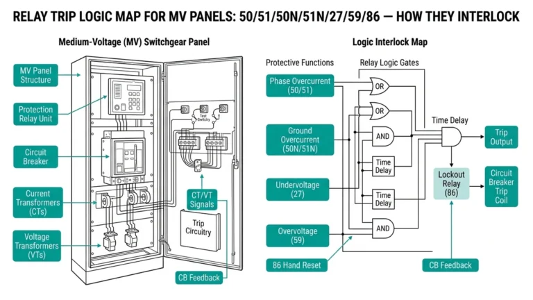
வெளிப்புறக் குறிப்பு: IEEE தர நிர்ணய சங்கம், மின்சார ஆற்றல் அமைப்பு சாதன செயல்பாட்டு எண்கள் மற்றும் தொடர்புப் பெயர்களின் IEEE C37.2 தரத்தில், கட்டுப்பாட்டு வயரிங் நடைமுறைகள் குறித்து விரிவான வழிகாட்டுதலை வழங்குகிறது, இது முனையப் பலகை லேபிளிங் மற்றும் ஒழுங்கமைப்பை நேரடியாகப் பாதிக்கிறது.
CT இரண்டாம் நிலை சுற்றுகளுக்கு, குறைந்தபட்சம் 10A தொடர்ச்சியான, விரும்பத்தக்க வகையில் 15-20A திறன் கொண்ட முனையங்களைப் பரிந்துரைக்கிறேன். இது சீர்குலைவுகளின் போது ஏற்படும் பிழை மின்னோட்டத்திற்கான வரம்பை வழங்குகிறது. இன்னும் முக்கியமாக, துண்டிக்கப்படுவதற்கு முன்பு தானாகவே குறுகிய மின்னழுத்தத்தை ஏற்படுத்தும் வகையிலான முனையங்களை CT சுற்றுகளுக்குக் குறிப்பிடவும்—இது பல ஆயிரம் வோல்ட்களைத் தாண்டக்கூடிய அபாயகரமான திறந்த-சுற்று CT மின்னழுத்தங்களைத் தடுக்கிறது.
டீன் ரெயில் மவுண்டிங் மூலம் தொழில்நுட்ப ரீதியாக சாத்தியமிருந்தாலும், உற்பத்தியாளர்களைக் கலக்க வேண்டாம் என்று நான் வலுவாக அறிவுறுத்துகிறேன். வெவ்வேறு டெர்மினல் குடும்பங்களுக்கு மாறுபட்ட துணைக்கருவிகள், லேபிளிங் அமைப்புகள் மற்றும் ஜம்ப்பர் உள்ளமைவுகள் உள்ளன. பராமரிப்புப் பணியாளர்கள் பல வகையான உதிரி பாகங்களைக் கையிருப்பில் வைத்திருக்க வேண்டும். ஒரு வசதி தணிக்கையில், பன்னிரண்டு சுவிட்ச்கியர் பிரிவுகளில் ஏழு வெவ்வேறு டெர்மினல் பிளாக் பிராண்டுகளைக் கண்டேன்—இது சரக்குப் பட்டியலில் கனவு போன்ற சிக்கல்களையும் இணைப்பு இணக்கத்தன்மைப் பிரச்சனைகளையும் உருவாக்கியது.
தொழில்முறை சிறந்த நடைமுறை, கட்டுப்பாட்டு வயரிங் பயன்பாடுகளுக்காக வயர் டக்ட் நிரப்புவதை குறுக்குவெட்டுப் பரப்பளவில் 40-50% ஆகக் கட்டுப்படுத்துகிறது. இது எதிர்காலச் சேர்த்தல்களை அனுமதிப்பதோடு, நிறுவலின் போது கடத்திகளுக்குச் சேதம் ஏற்படுவதையும் தடுக்கிறது. வெப்பத்தை உருவாக்கும் மின்சுற்றுகளுக்கு, நிரப்பும் அளவை 30-35% ஆகக் குறைக்கவும். நான், கடத்திகளின் குறுக்குவெட்டுப் பரப்பளவுகளை (இன்சுலேஷனுடன் சேர்த்து) கூட்டி, அதை 0.4 ஆல் வகுத்து டக்டின் அளவைக் கணக்கிடுகிறேன்.
வெளிப்புற MV சுவிட்ச் கியருக்காக, பின்வரும் தரநிலைகளைப் பூர்த்தி செய்யும் முனைகளைக் குறிப்பிடவும்:
– வெளிப்புறப் பயன்பாட்டுக் குறியீட்டுடன் கூடிய UL 1059
– IP20 குறைந்தபட்ச பாதுகாப்பு மதிப்பீடு (வெளிப்பட்ட இடங்களுக்கு IP67)
– எதிர்பார்க்கப்படும் சுற்றுப்புற வெப்பநிலையும், உட்புற வெப்பநிலை உயர்வும் அடங்கிய வெப்பநிலை மதிப்பீடு
– சூரிய ஒளி படும் இடங்களில் பயன்படுத்த UV-ஆன்டி எதிர்ப்புப் பொருட்கள்
– கடலோரப் பகுதிகளில் நிறுவும்போது துருப்பிடிக்காத எஃகு அல்லது சிறப்புப் பூச்சு கொண்ட உபகரணங்களைக் கருத்தில் கொள்ளுங்கள்.
நல்ல பெயர் பெற்ற உற்பத்தியாளர்களின் புஷ்-இன் (ஸ்பிரிங்-கேஜ்) டெர்மினல்கள், சரியாகப் பயன்படுத்தப்படும்போது, ஸ்க்ரூ-கிளாம்ப்பின் நம்பகத்தன்மையை பூர்த்தி செய்கின்றன அல்லது அதைவிட மேலானவை. இதன் முக்கிய நன்மைகள்: சீரான இணைப்பு விசை, அதிர்ச்சி எதிர்ப்பு மற்றும் வேகமான நிறுவல். உங்கள் கடத்தி வகைக்கு (ஒற்றை, பல, அல்லது ஃபெரூலுடன் கூடிய மெல்லிய பல) ஏற்ற குறிப்பிட்ட புஷ்-இன் மாடல் மதிப்பிடப்பட்டுள்ளதா என்பதை உறுதிப்படுத்திக் கொள்ளுங்கள். மேலும், 4mm²-க்கு மேற்பட்ட பெரிய கடத்திகளுக்கு ஸ்க்ரூ-கிளாம்ப் வடிவமைப்புகள் தேவைப்படலாம் என்பதையும் கருத்தில் கொள்ளுங்கள்.
மின்னழுத்தப் பிரிவுகளுக்கு இடையில் மாறும் சுற்றுகளுக்கு கவனமான கவனம் தேவை:
– குறைந்த மின்னழுத்தப் பெட்டகத்தில் மட்டுமே முனையங்களை நிறுவுங்கள்
– பொருத்தமான மதிப்பீடு கொண்ட ஃபீத்ரூ புஷிங்குகள் அல்லது தடைகளைப் பயன்படுத்தவும்.
– பொருந்தக்கூடிய தரநிலைகளின்படி கட்டம் பிரிப்பைப் பேணுதல்
– பாதுகாப்பு ஒருங்கிணைப்புக்காக இணைப்பு முனைகளைக் கருத்தில் கொள்ளுங்கள்
– மின்னழுத்த மதிப்பீடுகளை நிரந்தர லேபிள்களைக் கொண்டு தெளிவாகப் பதிவு செய்யவும்
சுவிட்ச் கியர் வசதிகளைப் பராமரித்த எனது அனுபவத்தின் அடிப்படையில், பின்வருவனவற்றைப் பராமரிக்கவும்:
– ஒவ்வொரு முனைய வகைக்கும் 5% நிறுவப்பட்டது
– ஒரு முழுப் பிரிவிற்கான முழுமையான லேபிளிங்/குறியீட்டுப் பொருட்கள்
– பயன்படுத்தப்பட்ட ஒவ்வொரு உள்ளமைப்பிற்கும் ஜம்பர்கள் மற்றும் பாலங்கள்
– இறுதிப் பிணைப்புகள், உறைகள் மற்றும் பொருத்தும் துணைக்கருவிகள்
– சிறப்பு முனையங்களில் தலா குறைந்தபட்சம் ஒன்று (உருக்கியமைத்த, துண்டிப்பான், பூமி)
நடுத்தர மின்னழுத்த ஸ்விட்ச்ஜியருக்கான கட்டுப்பாட்டு வயரிங் கூறுகளைத் தேர்ந்தெடுப்பதில், மின் செயல்திறன், சுற்றுச்சூழல் இணக்கத்தன்மை, நிறுவல் செயல்திறன் மற்றும் வாழ்க்கைச் சுழற்சிச் செலவுகள் ஆகியவற்றைச் சமநிலைப்படுத்துவது அவசியமாகும். இந்த வழிகாட்டியில் குறிப்பிடப்பட்டுள்ள உற்பத்தியாளர்களான—ஃபீனிக்ஸ் காண்டாக்ட், வெய்ட்முல்லர், வாகோ, ஏபிபி என்ட்ரெலெக் மற்றும் பிற—தங்கள் சீரான தரம் மற்றும் விரிவான தொழில்நுட்ப ஆதரவின் மூலம் தங்கள் நற்பெயரைப் பெற்றுள்ளனர்.
நினைவில் கொள்ள வேண்டிய அத்தியாவசியத் தேர்வு அளவுகோல்கள்:
நீங்கள் இன்று தேர்ந்தெடுக்கும் பாகங்கள் உங்கள் வசதிக்கு பல பத்தாண்டுகள் சேவை செய்யும். சரியான விவரக்குறிப்புகளில் நேரத்தை முதலீடு செய்வதும்—தரமான தயாரிப்புகளில் ஒரு மிதமான கூடுதல் பட்ஜெட் ஒதுக்குவதும்—நம்பகமான செயல்பாடு, திறமையான பராமரிப்பு மற்றும் தவிர்க்கப்பட்ட பழுதுகள் மூலம் பலன்களைத் தரும். உங்கள் அடுத்த சுவிட்ச்கியர் திட்டத்திற்கு இங்கு வழங்கப்பட்டுள்ள சரிபார்ப்புப் பட்டியல்கள் மற்றும் அளவுகோல்களைப் பயன்படுத்துங்கள், அப்போதுதான் நீங்கள் ஆதரிக்கும் அதிநவீன பாதுகாப்பு மற்றும் சுவிட்ச்சிங் உபகரணங்களுக்குத் தகுதியான கட்டுப்பாட்டு அமைப்புகளை உருவாக்க முடியும்.