Vous avez besoin des spécifications complètes ?
Téléchargez notre catalogue de produits 2025 pour obtenir les schémas détaillés et les paramètres techniques de tous les composants des appareillages de commutation.
Obtenir le catalogue
Téléchargez notre catalogue de produits 2025 pour obtenir les schémas détaillés et les paramètres techniques de tous les composants des appareillages de commutation.
Obtenir le catalogue Téléchargez notre catalogue de produits 2025 pour obtenir les schémas détaillés et les paramètres techniques de tous les composants des appareillages de commutation.
Obtenir le catalogue
Calculate transformer fault current from impedance percentage with correct units, and check voltage drop, parallel load sharing and test conditions.
Dernière mise à jour : .
Transformer impedance percentage (Z%) describes the short-circuit impedance on the transformer’s rated base. It affects prospective fault current, voltage regulation and parallel load sharing. Values depend on transformer rating and design; a nameplate value must be assessed together with its tolerance, reference temperature and tapping position.
Z% is the applied short-circuit voltage expressed as a percentage of the rated voltage of the energized winding, at rated current and frequency under the specified conditions. For a 10 kV/0.4 kV transformer with 6% impedance, approximately 600 V applied to the 10 kV winding produces rated current when the other winding is short-circuited. The value combines equivalent resistance and leakage reactance.
Comprendre ce que ce pourcentage représente physiquement transforme Z% d'une valeur nominale abstraite en une variable de conception que vous contrôlez.
Transformer impedance percentage expresses the voltage needed to produce rated current with the other winding short-circuited. The comparisons below describe direction of effect for otherwise comparable designs, not application-specific impedance requirements. Select the actual value through the fault-level and voltage-regulation studies.
| Relative impedance | Study focus | Principal compromis |
|---|---|---|
| Lower Z% | Voltage drop and motor-starting performance | Courant de défaut prospectif plus élevé et exigences plus strictes en matière de disjoncteur. |
| Intermediate Z% | Balance of voltage regulation and fault duty | Chute de tension équilibrée et limitation du courant de défaut. |
| Higher Z% | Fault-current reduction where voltage performance remains acceptable | Chute de tension plus importante en cas de surcharge et de démarrage du moteur. |
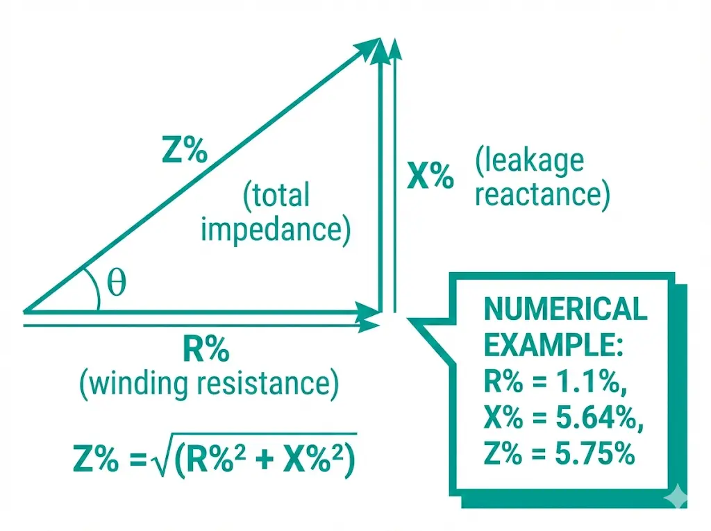
Transformer short-circuit impedance contains equivalent resistance R% and leakage reactance X%. The resistance term represents the active component associated with load losses at the reference conditions; load losses include winding I²R losses and additional stray losses. Obtain the tested load loss or the manufacturer’s equivalent-circuit data instead of assuming a fixed R-to-Z percentage.
Leakage reactance arises from magnetic flux that does not link both windings equally. Its share of total impedance depends on the design. If Z% and the equivalent R% are known on the same base and at the same reference conditions, calculate X% from √(Z%² − R%²).
La relation d'impédance est la suivante : Z% = √(R%² + X%²), où Z% est exprimé en pourcentage de la tension nominale. Pour un transformateur de distribution de 1 600 kVA avec Z% = 6%, l'application d'une tension primaire nominale de 6% (par exemple, 600 V sur un primaire de 10 kV) entraîne un courant à pleine charge dans le secondaire en cas de court-circuit.
Les fabricants ajustent le X% en modifiant l'espacement radial entre les couches d'enroulement. Une séparation plus importante augmente la réactance de fuite, et donc le Z%, ce qui limite le courant de défaut mais augmente la chute de tension sous charge. Ce compromis fondamental influence toutes les décisions relatives à la conception des transformateurs.
Specify the guaranteed impedance, applicable tolerance, tapping position and reference temperature in the purchase specification. IEC 60076-1 tolerances depend on the winding arrangement, specified impedance and tapping conditions; ±10% is not a universal rule for every transformer. A permitted manufacturing tolerance also does not prove that two transformers will share load acceptably in parallel.
Checks for interpreting impedance data
For an otherwise unchanged source and a three-phase fault at the secondary terminals, reducing transformer impedance increases its contribution to fault current. A complete study must also include the supply network and other connected sources.
The simplified calculation below assumes a balanced three-phase bolted fault at the secondary terminals, a stiff upstream source and no contribution from motors, generators or parallel transformers. It estimates the symmetrical RMS current; it is not a complete maximum/minimum short-circuit study.
Short-circuit current formula with S in kVA and UL in volts:
In (A) = S (kVA) × 1,000 ÷ (√3 × UL (V))
Isc (A) ≈ In × 100 ÷ Z% = S × 100,000 ÷ (√3 × UL × Z%)
Here S is the three-phase rated apparent power in kVA, UL is the secondary line-to-line voltage in V, and Z% is the numerical percentage (use 6.25, not 0.0625, in the percentage formula). The result is amperes. Use the voltage, impedance tolerance and reference conditions required by the chosen short-circuit calculation method.
Pour un transformateur de 2500 kVA, 20/0,4 kV avec Z% = 6,25% :
The simplified result is about 57.7 kA symmetrical RMS. With the same rating and voltage but Z% = 4%, the corresponding estimate is about 90.2 kA. These estimates inform equipment selection, but breaking duty, peak making duty and thermal withstand must each be checked against the complete study and applicable product ratings.
Neglecting upstream impedance gives a higher contribution from this transformer than the same calculation with a finite source impedance. It is not necessarily the installation’s absolute worst case: impedance tolerance, voltage factors and contributions from motors, generators or other transformers can matter. Refer all impedances to a common voltage and power base before combining them.
For series components on a common base: Rtotal% = ΣR%; Xtotal% = ΣX%; Ztotal% = √[(Rtotal%)² + (Xtotal%)²]. Adding impedance magnitudes directly is only an approximation when their impedance angles are sufficiently similar.
Example: on a 2 MVA base, a 250 MVA upstream short-circuit level gives a source-impedance magnitude of approximately 100 × 2/250 = 0.8%. If both source and transformer impedances are treated as predominantly reactive, adding this to 6% gives approximately 6.8%, reducing the estimated current by about 12%. Use separate R and X components when that approximation is unsuitable.
IEC 60076-5 addresses transformer thermal and dynamic withstand under external short circuits. Verify the specified fault current, duration and peak duty for the actual transformer and protection clearing times; do not assign every transformer a universal two-second duty or fixed 2.5 peak multiplier. See the Référence à la série IEC 60076 for the general transformer requirements. For the associated MV switching equipment, see sélection du disjoncteur à vide; the calculated 400 V terminal fault must be checked against the LV equipment ratings.
Voltage change depends on both impedance components and the load power factor. For a balanced load and a first-order estimate of transformer voltage drop, use the following expression for lagging power factor. Leading power factor reverses the reactive term; a detailed network study is needed for large transients or voltage-sensitive loads.
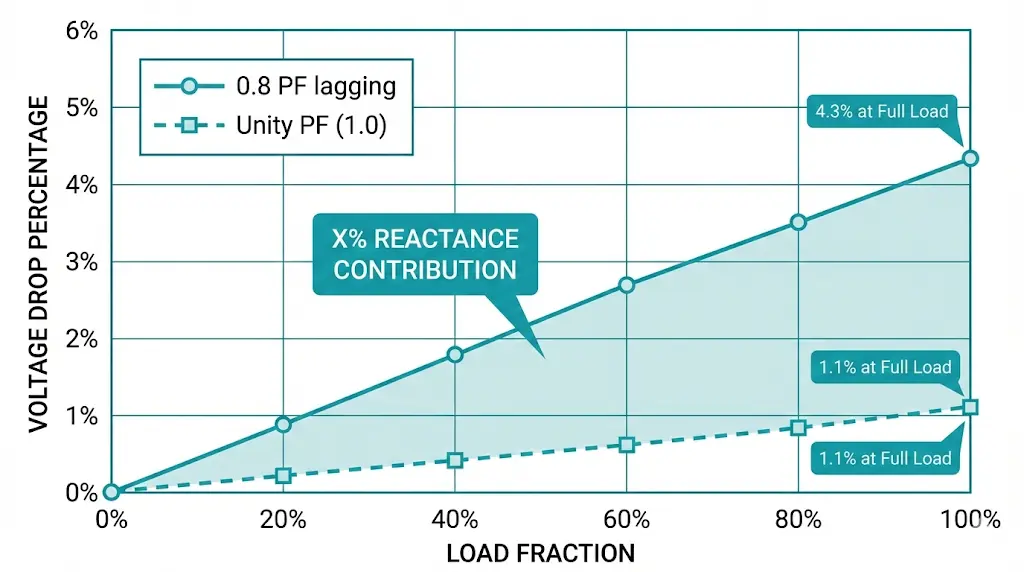
ΔV% ≈ (fraction de charge) × [R% × cos(φ) + X% × sin(φ)]
Pour un transformateur de 1 000 kVA avec R% = 1,1% et X% = 5,64% (total Z% = 5,75%), la chute de tension à pleine charge varie considérablement en fonction du facteur de puissance :
Avec un facteur de puissance de 0,8 en retard : ΔV% = 1,0 × [1,1 × 0,8 + 5,64 × 0,6] = 4,26%
Au facteur de puissance unitaire : ΔV% = 1,0 × [1,1 × 1,0 + 5,64 × 0] = 1,1%
In this example the total estimated drop is 4.26% at 0.8 lagging power factor, compared with 1.1% at unity: about 3.9 times as much. Correcting lagging power factor can reduce the reactive contribution, but capacitor selection also requires checks for harmonics, resonance and light-load voltage rise.
Régulation de tension expresses the change between no-load and loaded terminal voltage at a specified load and power factor. The R/X split matters, so Z% alone does not determine regulation. Use the following study priorities when comparing designs; the application name does not prescribe a universal impedance range.
| Demande | What to assess | Justification de la sélection |
|---|---|---|
| Distribution urbaine | Voltage limits and prospective fault current | Check regulation and equipment fault ratings together |
| Alimentateurs industriels | Motor starting and dynamic load behavior | Use actual starting-current and power-factor data |
| Générateur élévateur | Generator and network fault contributions | Coordinate generator, transformer and system protection |
| Alimentation du four à arc | Process current and voltage fluctuations | Use a specialist process and network study |
Pour obtenir des conseils complets sur spécification et acquisition de transformateurs de distribution, y compris la sélection d'impédance pour des applications spécifiques, consultez le portail d'ingénierie XBRELE.
Voltage-regulation study checks
Parallel transformers can provide additional capacity and operational flexibility. The usable combined capacity depends on load sharing, voltage matching and operating arrangements. Check compatibility before closing the parallel connection.
Verify these conditions together with the transformer manufacturer’s recommendations and the interconnecting cable or busbar impedances:
1. Compatible voltage ratios and tap settings: a no-load voltage mismatch causes circulating current. For two equal-rated units with equal impedance angles, each at 5% impedance on the same base, a 0.5% voltage mismatch gives an approximate circulating current of 0.5 / (5 + 5) = 0.05 per unit, or 5% of one unit’s rated current. Unequal ratings or impedance angles require the full common-base calculation.
2. Compatible phase displacement and phase sequence: verify the vector group, terminal identification and actual phase relationship at the connection point. Paralleling incompatible phase voltages can produce severe circulating or fault current.
3. Suitable impedance magnitude and angle: with matched no-load voltages, equal kVA ratings, similar impedance angles and negligible connecting-link differences, two 1,000 kVA units at 4% and 6% impedance would divide a 2,000 kVA load as follows:
Under these assumptions the 4% unit reaches 120% loading while the 6% unit reaches 80%. With unequal kVA ratings, use impedances on a common base; equal percentage impedances on each unit’s own rating give approximately proportional sharing when the impedance angles also match. Set acceptable matching tolerances from the allowable loading and the manufacturer’s assessment.
4. Verified polarity and connections: confirm polarity, phase sequence, grounding arrangement and tap positions during commissioning. Incorrect connections can create a short circuit when the parallel connection closes.
Lors de l'achat de transformateurs de remplacement pour des bancs parallèles existants, précisez l'impédance cible avec une tolérance explicite. Demandez une vérification des tests en usine avant l'expédition et confirmez les valeurs Z% réellement mesurées avant la mise en parallèle. Pour les éléments connexes pratique de la coordination de la commutation et de la protection utilisés dans les circuits de transformateurs, voir la base de connaissances techniques XBRELE.
The factory short-circuit test determines impedance and load losses at specified frequency, tapping and reference conditions. The outline below explains the measurement principle; the test requires an approved procedure, correctly rated equipment and qualified test personnel.
At rated current, Z% = 100 × measured short-circuit voltage / rated voltage of the energized winding. The measured input power is the load loss under the test conditions. It includes winding I²R loss and additional load losses, so it must not be treated as winding DC-resistance loss alone.
Correction de température brings measured results to the specified reference conditions. The following expression illustrates copper DC winding-resistance correction; it is not by itself the complete correction procedure for measured load loss or short-circuit impedance.
For copper DC winding resistance: Rcorrigé = Rmesuré × [(235 + Tréf.) / (235 + Tmesuré)], with both temperatures in °C.
Use the reference temperature and conductor constant specified for the transformer type, conductor material and applicable standard. A blanket “75°C for IEC, 85°C for IEEE” rule is not valid for every transformer.
In the usual equivalent-circuit correction, leakage reactance is treated as approximately temperature-independent. Correct the loss/resistance components using the prescribed test method and recompute the impedance magnitude. Compare parallel units at the same reference conditions and tapping position.
La documentation des valeurs d'impédance mesurées fournit des données de référence essentielles pour les futures études de coordination de la protection et les spécifications des transformateurs de remplacement. Pour composants de commutation qui protègent les installations de transformateurs, consultez le catalogue technique XBRELE.
Selecting Z% requires a balance between fault-current levels, voltage performance and equipment compatibility. Higher impedance can reduce symmetrical fault current, but it does not automatically reduce arc-flash incident energy: relay or breaker clearing time may change. Evaluate the protection settings along with the electrical design.
Cadre décisionnel :
| Priorité | Selection approach | Applications typiques |
|---|---|---|
| Régulation de tension | Compare candidate Z%, R/X and load power factor | Centres de données, installations de semi-conducteurs, fabrication de précision |
| Limitation du courant de défaut | Check maximum and minimum fault currents | Sous-stations urbaines, installations modernisées avec des disjoncteurs à puissance nominale limitée |
| Démarrage du moteur | Calculate starting dip using actual motor data | Installations industrielles équipées de gros moteurs à induction, exploitations minières |
| Fonctionnement en parallèle | Match on the basis of the load-sharing study | Augmentation de la capacité, mises à niveau de redondance |
Confirm the required impedance range, tolerance and tapping data with the manufacturer before purchase. A custom design can affect winding geometry, losses, size, lead time and price; there is no universal percentage cost premium. Request a project-specific technical proposal and quotation.
Pour les solutions de transformateurs techniques avec adaptation d'impédance spécifiée, contactez l'équipe technique de XBRELE via le Spécifications et approvisionnement des transformateurs portail.
Q : Comment calculez-vous le courant de court-circuit à partir de l'impédance du transformateur ?
A : For the simplified three-phase terminal-fault case, Isc ≈ In × 100/Z%, with In = S(kVA) × 1,000/[√3 × U(V)]. A 1,000 kVA, 400 V, 5% unit gives about 28.9 kA. This estimate neglects upstream impedance and other source contributions; use a complete study for equipment selection.
Q : Que se passe-t-il lorsque des transformateurs parallèles ont des valeurs d'impédance différentes ?
A : With matched voltages and similar impedance angles, the lower-impedance path takes more current. The actual split depends on kVA ratings, impedances on a common base, tap settings and connecting-link impedances. There is no fixed load-imbalance percentage for every impedance mismatch.
Q : Pourquoi le facteur de puissance affecte-t-il davantage la chute de tension que ne le suggère le pourcentage d'impédance seul ?
A : The approximate lagging-load drop is proportional to R% × cosφ + X% × sinφ. At unity power factor the reactive term is zero. In the worked example, 0.8 lagging gives 4.26% total drop versus 1.1% at unity; that ratio is specific to the chosen R% and X%.
Q : Les fabricants peuvent-ils construire des transformateurs avec des valeurs d'impédance personnalisées ?
A : A manufacturer may be able to meet a specified impedance range by changing the winding design. Feasibility, tolerances, losses, lead time and price require a project-specific assessment; do not assume a fixed cost premium.
Q : Comment la température affecte-t-elle l'impédance mesurée lors des essais sur le terrain ?
A : Winding resistance and load-loss components change with temperature. Use the prescribed correction method, conductor material and reference temperature from the applicable transformer standard and test specification. Do not apply a universal IEC or IEEE reference temperature to every design.
Q : Quelle tolérance d'impédance doit être spécifiée pour le fonctionnement en parallèle ?
A : Base the purchase tolerance on the existing unit’s measured impedance, rating, ratio, tap data and allowable load imbalance. Have the manufacturer confirm compatibility. A generic ±5% purchase tolerance or ±10% matching rule is not sufficient for every bank.
Q : Une impédance plus élevée signifie-t-elle toujours une meilleure protection contre les défauts ?
A : No. Higher impedance usually reduces the transformer’s symmetrical fault-current contribution, but may increase voltage drop and change protection clearing times. Verify fault duty, sensitivity, coordination and voltage performance together.
Calculation references: Schneider Electric — simplified transformer terminal short-circuit calculation; Schneider Electric — combining source and circuit impedances; Schneider Electric — unequal transformer impedances in parallel operation. Apply the relevant transformer and short-circuit standards to the final project calculation.