Нужны полные технические характеристики?
Загрузите наш каталог продукции 2025 года, чтобы ознакомиться с подробными чертежами и техническими параметрами всех компонентов распределительного устройства.
Получить каталог
Загрузите наш каталог продукции 2025 года, чтобы ознакомиться с подробными чертежами и техническими параметрами всех компонентов распределительного устройства.
Получить каталог Загрузите наш каталог продукции 2025 года, чтобы ознакомиться с подробными чертежами и техническими параметрами всех компонентов распределительного устройства.
Получить каталог
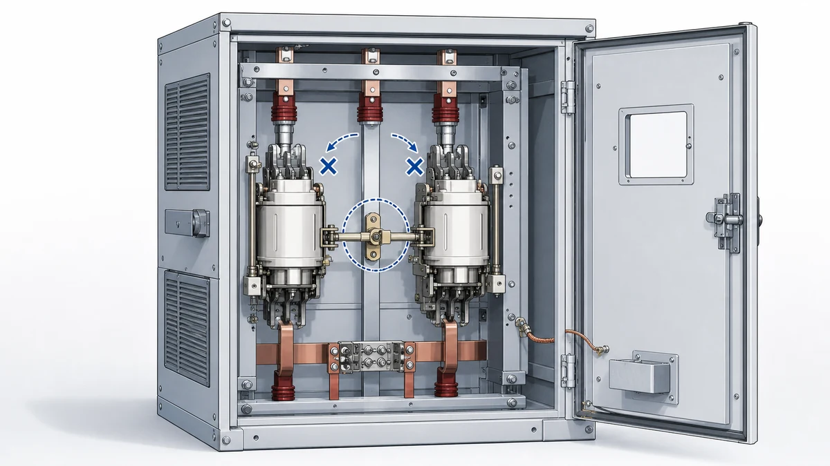
В реверсивном пускателе на вакуумных контакторах с механической блокировкой используются два контактора для вращения двигателя в прямом и обратном направлении; механическое устройство должно не допускать одновременного замыкания обоих контакторов. В схемах с вакуумными контакторами эта механическая функция важна, однако сама по себе она не подтверждает безопасность реверсивного пускателя. Полная проверка должна также подтвердить правильную компоновку конкретного семейства изделий, электрическую цепь блокировки, последовательность управления и область действия блокировки для данного оборудования.
Schneider публикует отдельные инструкции по установке механических блокировок для реверсивных контакторов; следовательно, монтаж и проверку необходимо выполнять по точной инструкции для соответствующего семейства контакторов, а не по универсальному шаблону сборки. Schneider также описывает реверсивные вакуумные контакторы и комплект для определённого номинала, в который входят механическая блокировка, силовые соединения и крепёжная пластина; сведения каталога подтверждают, что комплект предназначен для конкретного изделия и не является универсальным решением. В каталогах ABB представлены сборки реверсивных пускателей, сочетающие механические и электрические элементы блокировки, что подтверждает: безопасный реверс требует как физической блокировки, так и проверенной логики управления. В документации ABB ConVac также указано устройство блокировки выкатных вакуумных контакторов, которое не допускает перемещения при закрытом контакторе. Это показывает, что слово «блокировка» может обозначать разные функции в зависимости от оборудования.
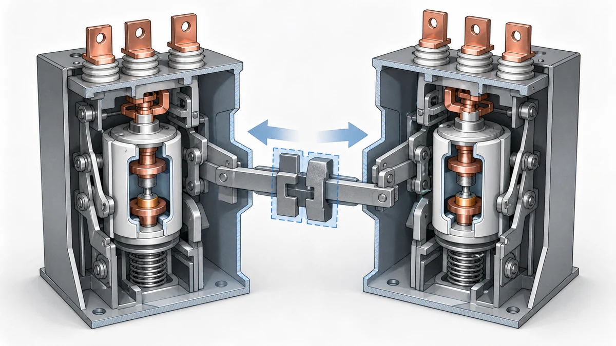
Перед проверкой механической блокировки определите точную модель вакуумного контактора, компоновку реверсивного пускателя и применимые к этому семейству изделий комплект и инструкцию производителя. Не предполагайте, что блокировку от контактора другого типоразмера, серии или сборки пускателя можно перенести на это оборудование. Исследованные материалы показывают, что производители публикуют отдельные инструкции по установке и определяют комплекты для конкретных сборок, поэтому первый шаг проверки — сопоставить оборудование с документацией.
Убедитесь, что установленная механическая блокировка, крепёжная пластина, силовые соединения и сопутствующие детали соответствуют предусмотренной компоновке реверсивных вакуумных контакторов. Если сборка поставлена комплектом, проверьте, что это комплект для заданного номинала контактора и нужного семейства изделий. Если в инструкции указана определённая ориентация монтажа или положение тяги, при осмотре следует руководствоваться этим указанием.
На этом этапе не нужно придумывать размеры, значения момента затяжки или зазоры. Следует сравнить фактическую сборку с опубликованными инструкциями производителя и утверждённой документацией на пускатель.
После отключения оборудования в соответствии с правилами безопасности объекта осмотрите физическое состояние пары реверсивных контакторов. Должно быть ясно, какой контактор отвечает за прямое, а какой — за обратное направление; механическая блокировка должна находиться между ними в предусмотренном положении. Проверьте, нет ли незакреплённых деталей, отсутствующих крепёжных элементов, видимых повреждений, перекоса, препятствий или признаков принудительного перемещения контактора. Инструкция Schneider Electric по установке механической блокировки — основной источник требований к конкретному изделию, указанных здесь. Согласуйте логику реверса с последовательностью операций для безопасной работы выкатного контактора , если контактор установлен в выкатной ячейке.
При качественном механическом осмотре нужно ответить на простой вопрос: может ли каждый контактор пройти предусмотренный ход без заедания, когда другой контактор разомкнут, и надёжно ли блокировка препятствует замыканию противоположного контактора, когда один уже замкнут? Если механизм заедает, движется с трением или для его работы требуется изгиб корпуса, переходить к испытаниям под напряжением нельзя.
Не смазывайте, не сгибайте, не подпиливайте, не подкладывайте прокладки и не изменяйте блокировку, если инструкция производителя прямо этого не разрешает. Механическая блокировка — элемент безопасности в составе пускателя, и её изменение на месте может повлиять на блокирующее действие.
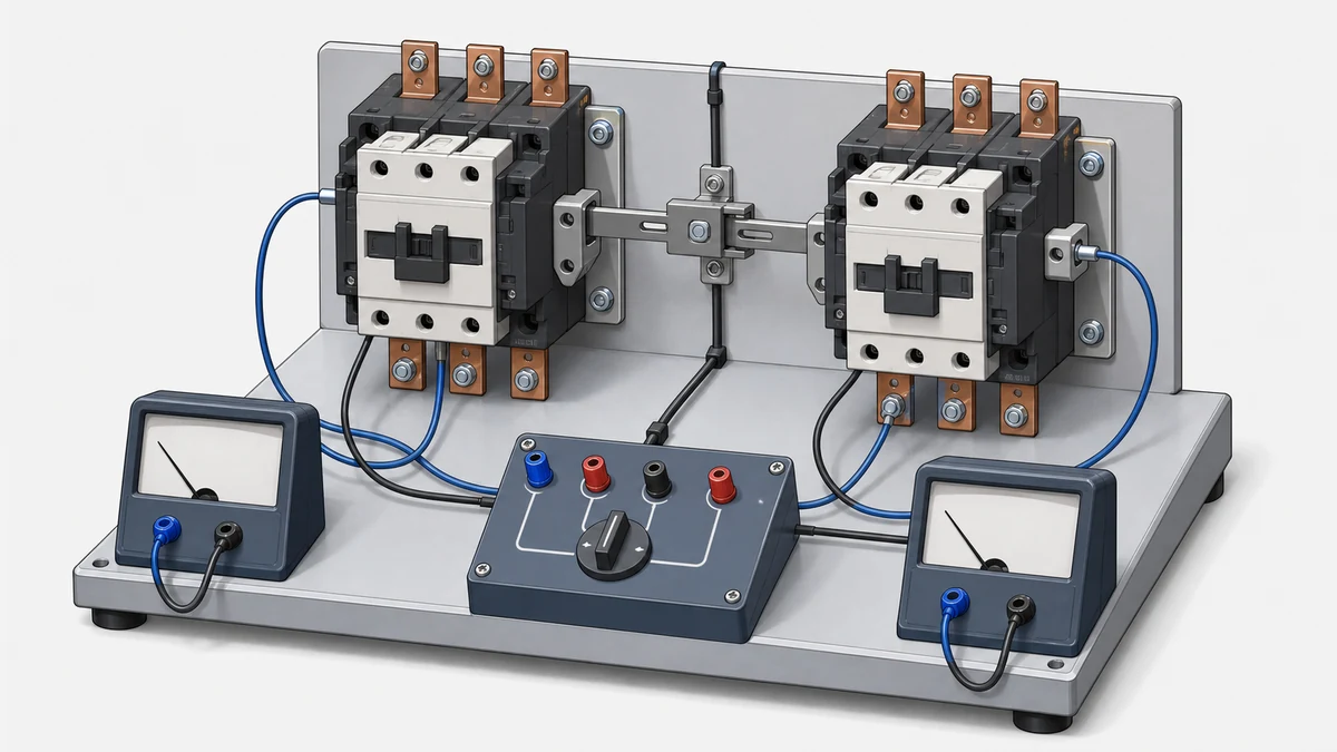
Сначала выполните базовую последовательность проверки в контролируемом обесточенном состоянии, используя разрешённый производителем способ управления контакторами. Начните с обоих разомкнутых контакторов. Включите контактор прямого хода и убедитесь, что механическая блокировка не позволяет замкнуть контактор обратного хода. Верните контактор прямого хода в разомкнутое состояние. Затем включите контактор обратного хода и убедитесь, что механическая блокировка не позволяет замкнуть контактор прямого хода. Верните оба устройства в разомкнутое состояние и повторите проверку, если этого требует производитель или процедура объекта.
Это испытание подтверждает непосредственное механическое назначение блокировки: предотвращать одновременное замыкание вследствие механического перемещения двух реверсивных контакторов. Оно не подтверждает правильность цепи управления, правильность подключения вспомогательных контактов или безопасную последовательность работы пускателя под напряжением.
В практической записи о проверке следует указать идентификацию контакторов, применимый документ с инструкциями, результат блокировки в обоих направлениях и любые аномалии движения. Если один контактор может замкнуться, когда другой уже замкнут, прекратите проверку и считайте пускатель не прошедшим её.
Реверсивный пускатель не должен полагаться только на механическую блокировку. Каталожные данные ABB о реверсивных пускателях показывают сборки с механическими и электрическими элементами блокировки; это подтверждает общий принцип безопасности: физическая блокировка и логика управления должны быть исправны одновременно.
После успешного механического испытания проверьте электрическую блокировку по утверждённой принципиальной схеме управления. При активном режиме обратного хода команда прямого хода не должна включать катушку контактора обратного хода; при активном режиме прямого хода команда обратного хода не должна включать катушку контактора прямого хода. Логику вспомогательных контактов, командные устройства, разрешающие сигналы и любую логику реле управления следует сверить с фактической проводкой и чертежами пускателя. Перед утверждением схемы реверса сопоставьте оба уровня блокировки с руководством по электрической и механической блокировке контакторов .
Это особенно важно, поскольку механическая блокировка может препятствовать одновременному замыканию, но не исправляет неверную команду на катушку. Если цепь управления снова и снова подаёт команды на оба контактора, механическая блокировка может предотвратить замыкание во время испытания, однако в системе управления пускателя всё равно остаётся неисправность, которую необходимо устранить.
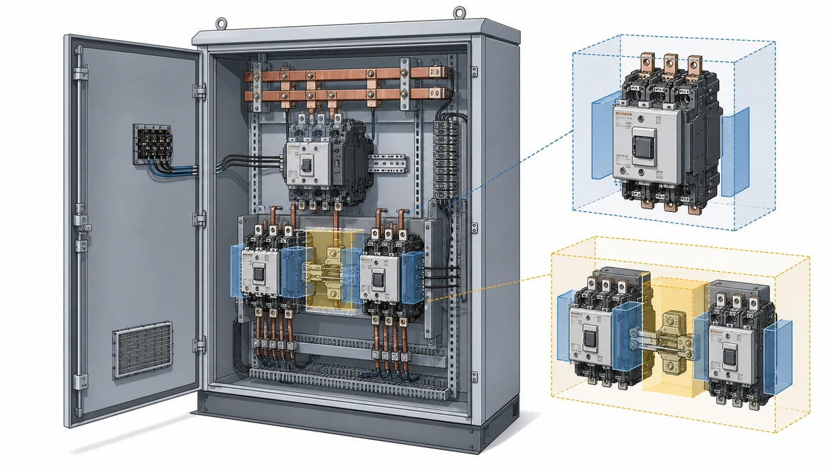
Слово «блокировка» не всегда обозначает одну и ту же функцию. В реверсивном пускателе механическая блокировка обычно означает устройство, не позволяющее одновременно замкнуть вакуумные контакторы прямого и обратного хода. Для выкатного оборудования с вакуумными контакторами в документации ABB ConVac указано устройство блокировки, препятствующее перемещению контактора при замкнутом состоянии. Это другая функция безопасности с другой областью проверки. Ознакомьтесь с семейством вакуумных контакторов , чтобы понять контекст оборудования, к которому относится рассматриваемая конфигурация контактора.
Поскольку область действия зависит от оборудования, в записях о проверке следует точно указывать, какая именно блокировка испытывалась. Проверку механической блокировки реверсивного пускателя нельзя использовать как доказательство работы блокировки выкатного механизма; проверка блокировки выкатного механизма не доказывает работу блокировки контакторов прямого и обратного хода.
Это различие позволяет избежать распространённой ошибки в документации: отметки «блокировка проверена» без указания, какую функцию блокировки фактически проверили.
Реверсивный пускатель на вакуумных контакторах с механической блокировкой можно принять только при условии, что установленные детали соответствуют документации нужного семейства изделий, механическая блокировка препятствует замыканию в обоих направлениях, контакторы возвращаются в нормальное разомкнутое состояние без заеданий, а логика электрической блокировки соответствует утверждённой схеме управления.
В записи следует избегать неподтверждённых утверждений об универсальной совместимости, предполагаемом диапазоне номиналов или неуказанных характеристиках. Вместо этого результат нужно привязать к конкретной сборке вакуумных контакторов и инструкции производителя, использованной при проверке.
Если какая-либо часть пускателя не соответствует задокументированной компоновке, проблему следует устранить до подачи напряжения. Это касается неправильных деталей блокировки, отсутствующего крепежа, неясной идентификации контактора, непроверенных силовых соединений и логики электрической схемы, допускающей одновременные команды на катушки. См. руководство по принципиальным схемам вакуумных контакторов для цепей катушек, вспомогательных контактов и логики разрешения пуска.
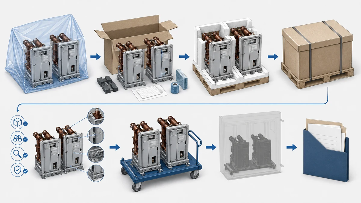
Это схема реверсивного пускателя, в которой применяются вакуумные контакторы и механическое блокирующее устройство, предназначенное для предотвращения одновременного замыкания контакторов прямого и обратного хода. Механическая блокировка входит в состав реверсивной схемы, однако для правильной работы пускателя также необходимы верный выбор изделия, монтаж по утверждённым требованиям, силовые соединения, крепёжные детали и логика электрической блокировки.
До электрических испытаний проверьте, что механическая блокировка предназначена для нужного семейства вакуумных контакторов, установлена по инструкции производителя и блокирует противоположный контактор как при прямом, так и при обратном ходе. Также осмотрите оборудование на предмет отсутствующего крепежа, перекоса, препятствий, повреждений и движений, указывающих на заедание или принудительный ход.
Механическая блокировка не подтверждает, что цепь управления подключена правильно, вспомогательные контакты работают как предусмотрено или логика команд предотвращает одновременное включение катушек. Она подтверждает только механическую функцию блокирования в пределах своего назначения. Электрическую блокировку и последовательность управления всё равно необходимо проверить по утверждённой схеме.
Такая процедура может не учитывать особенности монтажа конкретного изделия, ориентацию установки, состав комплекта или область действия блокировки на оборудовании. Отдельные инструкции Schneider по установке блокировок и каталожные комплекты для реверсивных вакуумных контакторов показывают, что эти сборки не универсальны. Поэтому проверку следует выполнять по точной инструкции для соответствующего семейства изделий, а не по универсальному перечню механических проверок.
Блокировка реверса не позволяет одновременно замкнуть контакторы прямого и обратного хода в пускателе. Блокировка выкатного механизма, например указанная в документации ABB ConVac на выкатные вакуумные контакторы, препятствует перемещению при замкнутом контакторе. Обе являются блокировками, но они предотвращают разные опасности и требуют разных этапов проверки.