Need Full Specifications?
Download our 2025 Product Catalog for detailed drawings and technical parameters of all switchgear components.
Get CatalogDownload our 2025 Product Catalog for detailed drawings and technical parameters of all switchgear components.
Get CatalogDownload our 2025 Product Catalog for detailed drawings and technical parameters of all switchgear components.
Get Catalog
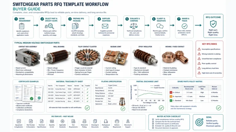
For engineers reviewing a Single Line Diagram (SLD) for a secondary distribution project, a recurring decision point arises: Where do we draw the line between a Load Break Switch (LBS) and a Vacuum Circuit Breaker (VCB)?
Visually, they often appear identical on a panel schedule, typically sitting alongside other switchgear components. However, misapplication here is not just a semantic error; it’s a capital risk. Over-specifying VCBs inflates project costs unnecessarily (often by 300%), while under-specifying an LBS in a fault-clearing role compromises safety compliance and can lead to catastrophic failure.
The distinction is foundational to medium voltage (MV) distribution:
This article moves beyond basic definitions to explore the engineering reality of the SF6 LBS: its internal physics, why it remains the standard for Ring Main Units (RMUs), and how to apply it correctly under IEC 62271 standards.
An SF6 load break switch is a mechanical switching device capable of making, carrying, and breaking currents under normal circuit conditions. Crucially, strictly defined by IEC 62271-103, it must also be capable of making on a short circuit (closing onto a fault) safely, even though it cannot break that fault.
The terminology often confuses junior engineers. Let’s clarify the three core capabilities:
It is critical to understand the mechanical limitation: An LBS cannot interrupt a short circuit. The contact speed and arc-quenching energy are insufficient to handle the kilo-amperes of a fault scenario. Attempting to open an LBS during a fault will result in thermal runaway and switchgear explosion.
This is why LBS units in transformer feeders are invariably paired with HRC Fuses. The fuses provide the fault clearance, while the switch handles manual operations.
External Reference: For a deeper dive into switchgear definitions, refer to the IEC Electropedia (International Electrotechnical Vocabulary) for standard terminology on “Switch-disconnectors”.
Why do we still rely on Sulfur Hexafluoride (SF6) despite intense environmental scrutiny? Because physically, it is nearly unbeaten as an interruption medium for compact switchgear compared to air or oil.
SF6 is an “electronegative” gas. This means its molecules have a high affinity for free electrons. When an arc forms (which is essentially a stream of electrons), the SF6 molecules capture these free electrons to form heavy negative ions:
SF6 + e– → SF6–
These heavy ions are much less mobile than free electrons, which drastically reduces the conductivity of the arc plasma. This process effectively “starves” the arc of its conductive path.
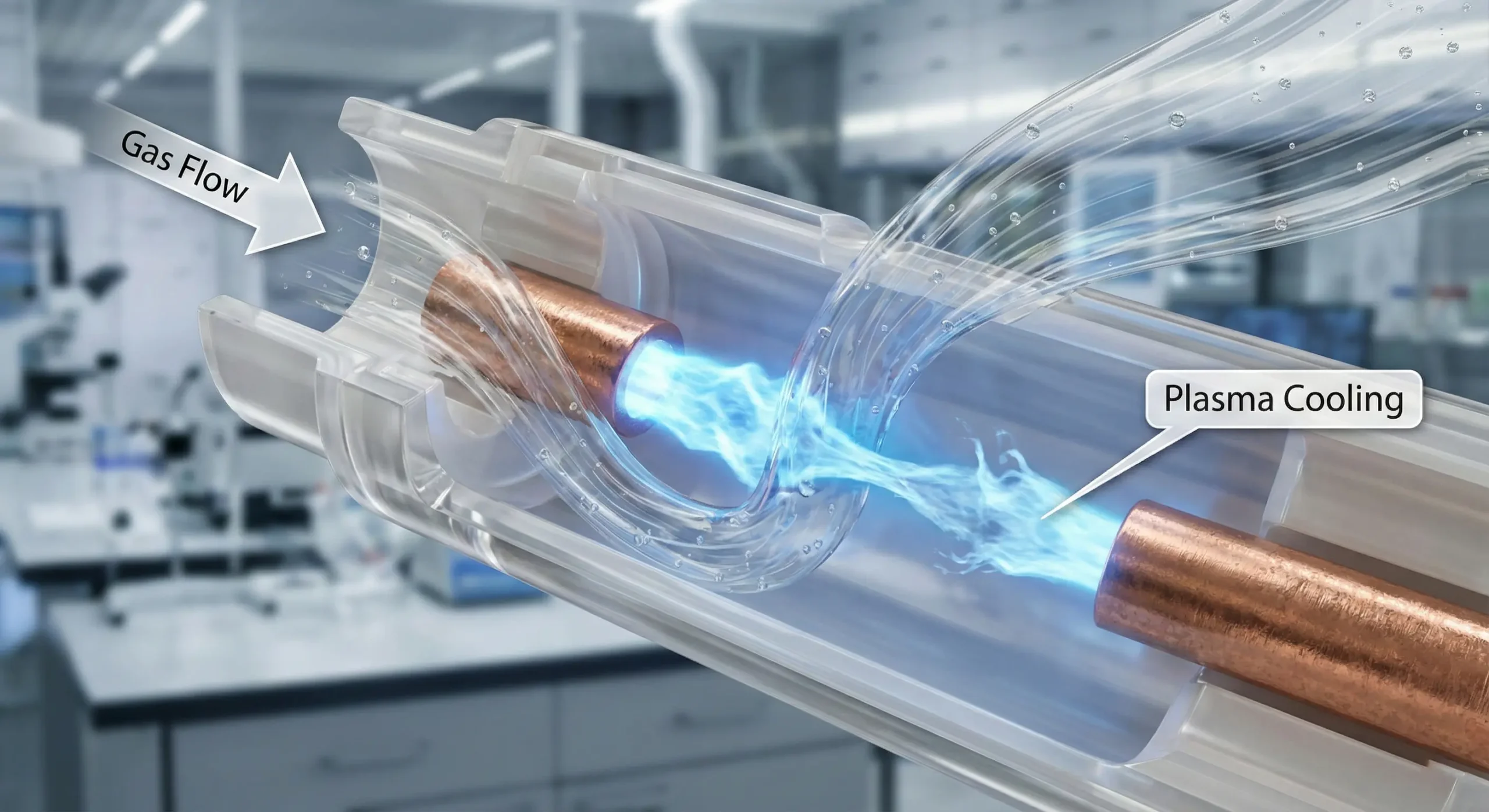
SF6 has a unique property where its thermal conductivity spikes at arc dissociation temperatures (around 2000K–3000K). This allows it to transport heat away from the contact zone far more efficiently than air. This rapid cooling is essential for Dielectric Recovery—ensuring that when the AC current hits “zero,” the gap recovers its insulation strength faster than the voltage can rise across it (Transient Recovery Voltage).
Unlike oil, which degrades into carbon sludge, or air, which forms ozone, SF6 gas recombines after the arc is extinguished.
SF6 ↔ S + 6F
Once the arc cools, the sulfur and fluorine atoms recombine back into stable SF6. This “self-healing” property allows a sealed LBS to operate for 20+ years without gas refill.
If a Vacuum Circuit Breaker (VCB) can handle both loads and faults, why not use them universally? The answer lies in network topology and Capital Expenditure (CAPEX) efficiency.
Secondary distribution typically employs a ring structure to ensure redundancy. In a standard Ring Main Unit (RMU), you might see a “CCF” configuration: two Cable switches and one Fuse switch.
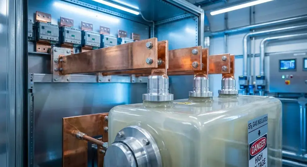
Space is currency in urban infrastructure. A standard VCB assembly requires bulky operating mechanisms (spring charging motors) and vacuum bottles.
An SF6 LBS takes advantage of the gas’s high dielectric strength (2.5x that of air), allowing phase-to-phase clearances to be minimized. This enables the construction of compact Gas-Insulated Switchgear (GIS) that can fit inside narrow sidewalk substations or wind turbine towers—places where traditional air-insulated switchgear simply wouldn’t fit.
How does the switch actually kill the arc? It’s not just about opening contacts; it’s about fluid dynamics inside the gas tank.
This is the most common mechanical design for load breaking.
Used in heavier-duty applications or specific brands (like Schneider Electric’s older ranges), this method uses the energy of the arc itself.
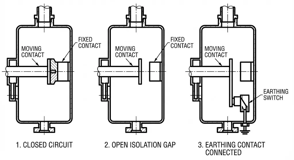
Modern safety standards (IEC 62271-200) have effectively mandated the Three-Position Disconnector in gas-insulated switchgear. This replaces the old approach of using separate switches for isolation and earthing, which relied heavily on complex key interlocks to prevent errors.
The three positions are mechanically integrated into a single shaft or interlocked assembly:
The mechanical interlock makes it physically impossible to go from ON directly to EARTH. You must pass through OFF. This intrinsic safety prevents the “human error” scenario of earthing a live line, which is a leading cause of electrical accidents in older switchgear.
Related Component: For detailed specs on safety grounding, refer to our Indoor HV Earthing Switches (JN15 Series) which are often integrated into air-insulated versions of these panels.

One of the most technically interesting aspects of the LBS is how it mimics a circuit breaker when paired with fuses. This is governed by IEC 62271-105.
In a “Switch-Fuse Combination,” the LBS mechanism is not just manual; it has a stored-energy opening spring that can be triggered remotely.
The Sequence of Operation:
Why is this critical? If only one fuse blew and the switch stayed closed, the motor or transformer would run on two phases (“single-phasing”), leading to overheating and failure. The striker linkage ensures that a fuse operation results in complete isolation.
For a vacuum circuit breaker manufacturer, the VCB is the flagship product. But for a network planner, it’s a specific tool for a specific problem.
| Parameter | SF6 Load Break Switch (LBS) | Vacuum Circuit Breaker (VCB) |
|---|---|---|
| Core Function | Load Management & Isolation | Fault Interruption & Protection |
| Fault Clearing | No (Must use HRC Fuses) | Yes (Up to 40kA+) |
| Switching Life | Moderate (IEC Class E3, ~100 full load ops) | High (IEC Class E2/C2, ~10,000 full load ops) |
| Control Complexity | Simple (Spring mechanism) | Complex (Relays, CTs, Aux Power) |
| Cost Basis | Low (Base cost) | High (3x – 4x LBS cost) |
| Typical Role | RMU Ring Cables, manual sectionalizing | Main Feeders, Critical Generators |
SF6 is a potent greenhouse gas (GWP of 23,500). New regulations (like the EU F-Gas Regulation) are pushing for a phase-out of SF6 in medium voltage switchgear. The Alternatives:
While the industry transitions, SF6 remains dominant in existing infrastructure and markets where compact size is the primary constraint.
Q1: Can I operate an SF6 LBS if the gas pressure is low? Strictly No. The arc-quenching capability depends on gas density. If the manometer indicates low pressure (usually a red zone), mechanical interlocks should prevent operation. Forcing operation in this state can lead to a flashover and tank rupture.
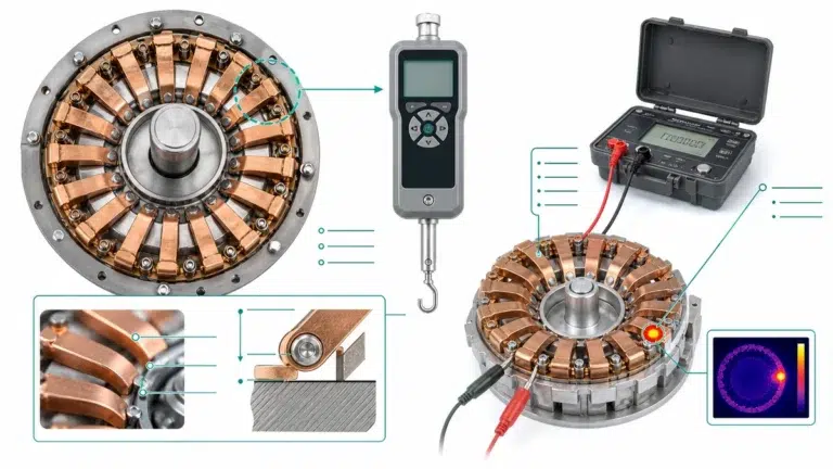
Q2: How do I test an installed SF6 LBS? Unlike VCBs, you cannot easily test the contact resistance of a sealed unit. Maintenance primarily involves:
Q3: Can an LBS break a capacitor bank current? Standard LBS units struggle with capacitive currents (lines or capacitor banks) due to restrike risks. You must specify a switch tested to IEC 62271-103 Class C1 or C2 if you intend to switch unloaded cables or capacitor banks frequently.
The SF6 load break switch remains the backbone of secondary distribution not because it is the most powerful device, but because it is the most appropriate one. It offers the optimal balance of safety, compactness, and cost for the vast majority of switching nodes in a grid.
Successful network design relies on using VCBs to protect the heavy assets and LBS units to manage the flow. Confusing the two leads to bloated budgets or compromised safety.
An in-depth technical guide exploring SF6 gas insulation properties, arc quenching mechanisms, and a critical comparison between LBS and VCB for medium voltage networks.
Download SF6 LBS Guide