Request a Quote for High-Voltage Components&Equipment
Tell us your requirements — rated voltage, model, quantity, and destination — and our XBR Electric team will prepare a detailed quotation within 24 hours.
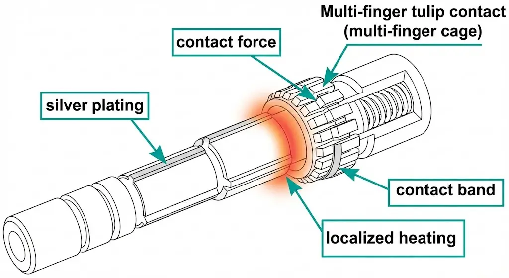
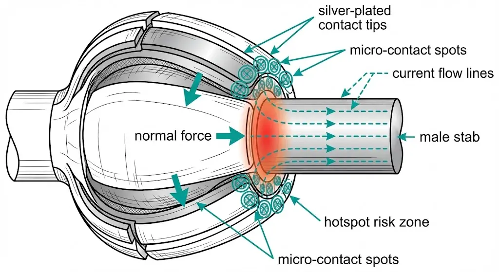
Tulip contacts are the separable, high-current interface used in drawout MV equipment: the moving primary stab mates into a spring “cage” of multiple copper fingers (“petals”) on the fixed side. The design spreads current across many micro-contact spots, so the joint can tolerate vibration, thermal cycling, and repeated insertions—until force or surface condition is lost.
Three things govern whether a tulip joint stays cool and stable:
Normal force: the petals must maintain pressure around the circumference. If force relaxes (fatigue, prior overheating, wrong stab size, deformation), the true contact area shrinks and resistance rises.
Surface finish (silver plating): silver is widely used because it supports low interface resistance and more forgiving behavior under sliding contact. In practice, spare tulip contacts are often silver plated around 8–12 micrometers, and common assemblies cover 630 A to 5000 A, depending on geometry and cooling.
Engagement quality: centering and insertion depth decide whether the whole ring of fingers shares current or whether one sector gets overloaded.
Heating is an interface phenomenon. A small increase in contact resistance becomes a large thermal penalty at high current because the joint’s loss is proportional to I²R.
Standards context: general requirements for AC high-voltage switchgear and controlgear are covered under IEC 62271-1. IEC Webstore
Heating: separate “normal warm” from “damage-in-progress”
A healthy tulip connection can run warm. A failing one announces itself with a localized, repeatable hot spot that tracks a single interface.
Make your thermal checks comparable:
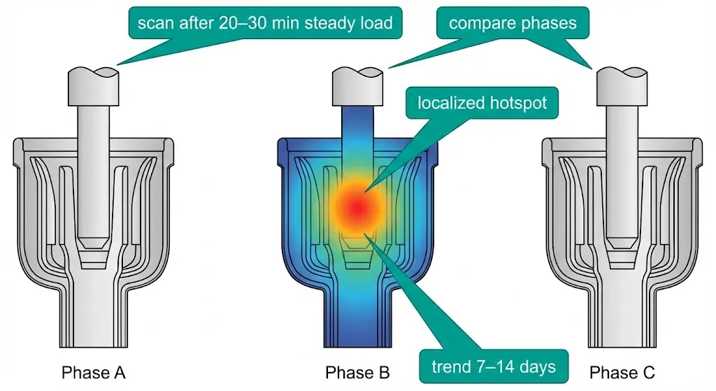
Scan after 20–30 minutes at steady load, and keep the camera distance/angle consistent.
Log current (A) and ambient (°C). A joint that looks acceptable at 400 A can become the dominant hotspot at 1200 A.
What to look for:
Localization: “normal warm” is broad along the conductor path; a failing tulip joint is a tight hot spot near the mating band.
Phase comparison: under similar loading, one phase running 10–20°C hotter at the same joint location usually means force loss, film contamination, or uneven engagement—not “random load.”
Repeatability: if the hot spot moves after re-racking/re-seating, suspect alignment or insertion depth. If it comes back to the same place after a careful re-seat, suspect permanent surface/force damage.
Trend: two scans 7–14 days apart under similar duty are more actionable than a single snapshot.
If the hot point is near the insulated spout/contact box area (not only on the metal joint), review contamination paths and tracking evidence here: epoxy contact box basics
Pattern-based thermography schematic highlighting localized hotspots versus uniform conductor warming.
[Expert Insight]
A “fixed” hotspot that returns at the same axial band usually means the true engagement band is damaged, not just dirty.
IR images without load context (A, time at load, ambient) often lead to the wrong corrective action.
Re-seat improvements that vanish at the next peak duty cycle often indicate marginal normal force.
Root causes that create high resistance in tulip contacts
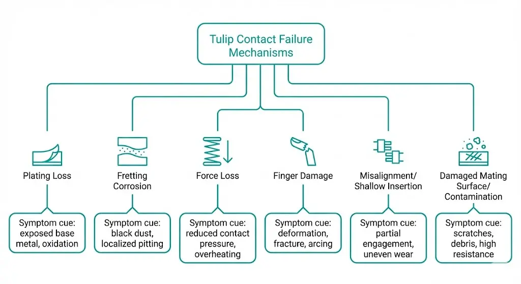
Once you’ve confirmed localized heating, the root causes are usually one of these interface degradations:
Plating loss in the working band: when the silver is worn through where the stab actually sits, the joint becomes more sensitive to films and fretting debris.
Fretting corrosion: micro-motion plus thermal cycling generates debris that behaves like a resistive layer and accelerates wear.
Normal-force loss: spring relaxation or heat-softening reduces the number and stability of micro-contact spots, especially in higher-duty joints.
Finger damage / uneven engagement: bent or cracked petals concentrate current into a smaller sector and create a repeatable hot spot.
Misalignment or shallow insertion: only part of the circumference carries current; hotspots may shift when the unit is re-seated.
Damaged mating surface: scoring, pitting, burrs, or out-of-round stabs scrape plating and create high points and debris.
Failure mechanism tree showing how surface condition and force loss drive contact resistance and heating.
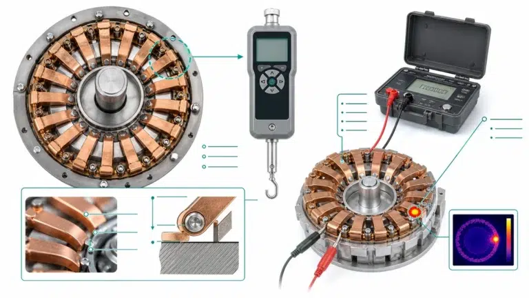
Inspection & measurement workflow you can run in the field
The goal is repeatable evidence, then controlled correction steps.
Capture operating context first
Record load current (A), ambient (°C), and time at load (min).
Shoot thermal images after 20–30 minutes at steady duty from the same viewpoint.
Visual inspection (after safe isolation)
Contact band: worn ring, discoloration, pitting, black debris.
Finger symmetry: “one-side heavy wear” is a strong hint of alignment or shallow engagement.
Cleaning (only if allowed by OEM method) Use non-residue approaches; avoid aggressive abrasion that removes plating. If film returns quickly, assume the underlying force/surface problem still exists.
Re-test under comparable duty If a hotspot disappears once and returns under the next similar load, treat it as a degradation trend, not a success. When available, add a low-resistance measurement (DLRO) and record the joint value in milliohms before and after correction steps; the absolute number varies by design, but the change and repeatability are what matter.
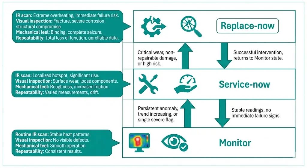
Replacement criteria: when cleaning/tightening is no longer enough
Use repeatability + condition to decide.
Tier A — MONITOR
Stable thermal profile; no persistent localized hotspot.
Light polish marks only; no pitting or heavy debris.
Smooth, symmetric engagement.
Trend check: confirm stability over 7–14 days under similar duty.
Tier B — SERVICE-NOW (correct, then verify)
Localized warming that improves after re-seat/controlled cleaning but remains noticeable around higher duty (e.g., ~1200 A running load).
Partial plating loss, moderate fretting marks, early discoloration.
Uneven engagement pattern or suspected shallow insertion.
Re-scan after 20–30 minutes at steady load.
Tier C — REPLACE-NOW
Hotspot persists after controlled re-seat/clean and repeats at the same location; trending worse duty-to-duty.
Deep pitting, heavy black debris, visible arcing traces, severe discoloration, missing/cracked petals.
Weak “snap” feel or obvious deformation; mating surface visibly scored or out-of-round.
Decision ladder summarizing repeatability- and condition-based criteria for replacement.
[Expert Insight]
If the mating stab surface is damaged, replacing only the tulip contact often shortens the time to the next hotspot.
“Replace-now” is usually triggered by repeatability (same place, same symptom) more than by a single high temperature.
Photograph the contact band position before disassembly; it helps distinguish shallow engagement from surface degradation.
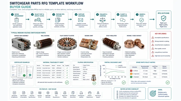
Replacement planning that avoids repeat failures (parts + interface matching)
A tulip contact replacement works when you treat it as an interface system, not a single spare part. Many repeat heating cases happen because force and surface compatibility are never verified, so the new contact begins fretting early and the hotspot returns within 30–60 days under peak duty.
Send an RFQ-ready “replacement data pack”:
Photos: close-up of the working band, any pitting/discoloration, plus a full view showing alignment and insertion direction.
Electrical duty: typical and peak current (A); steady vs cyclic loading.
Thermal evidence: IR images with ambient (°C) and time at load (min).
Mechanical notes: insertion feel (smooth/gritty), any looseness, whether the hotspot shifts after re-seat.
Mating surface condition: scoring/burrs/ovalization on the stab/spout; if you can, include approximate engagement length (mm).
Environment: dust, salt fog, chemical exposure, and ventilation inside the bay.
Share the data pack with XBRELE and we’ll help match the contact configuration and replacement scope (contact-only vs contact plus mating-surface service) to stop repeat heating.
FAQ
1) What’s the quickest way to confirm a tulip-joint issue is localized? Compare the same joint across phases under similar duty; a consistent outlier usually indicates an interface problem.
2) Can a joint look clean and still overheat? Yes—low normal force or uneven engagement can create high resistance without obvious contamination.
3) Why does re-seating sometimes reduce temperature temporarily? It can redistribute contact spots, but it doesn’t restore worn plating or weakened spring behavior.
4) Is one thermal scan enough to justify replacement? Often it’s better to confirm repeatability under comparable load, unless there is clear mechanical damage or severe surface deterioration.
5) What information best prevents ordering the wrong replacement contact? Working-band photos plus load context (current, duty pattern) and clear fit/engagement notes usually remove most ambiguity.
6) What’s a common reason new contacts fail soon after replacement? A damaged mating surface or alignment problem can keep scraping the interface and drive fretting even with the correct new part.
Hannah is the Administrator and Technical Content Coordinator at XBRELE. She oversees website structure, product documentation, and blog content across MV/HV switchgear, vacuum breakers, contactors, interrupters, and transformers. Her focus is delivering clear, reliable, and engineer-friendly information to support global customers in making confident technical and procurement decisions.