Need Full Specifications?
Download our 2025 Product Catalog for detailed drawings and technical parameters of all switchgear components.
Get CatalogDownload our 2025 Product Catalog for detailed drawings and technical parameters of all switchgear components.
Get CatalogDownload our 2025 Product Catalog for detailed drawings and technical parameters of all switchgear components.
Get Catalog
The operating mechanism of a vacuum circuit breaker determines far more than contact motion. It dictates switching speed, mechanical endurance, maintenance burden, and ultimately—protection reliability. Spring, magnetic actuator, and electric repulsion mechanisms each reflect distinct engineering philosophies, with measurable differences in field performance.
This comparison examines the physics, specifications, and selection logic engineers need to match mechanism technology to actual application demands.
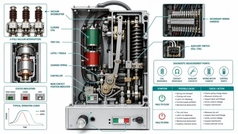
The vacuum interrupter gets the attention—but the operating mechanism does the work.
Contact separation speed during fault interruption, closing force consistency across thousands of operations, and long-term mechanical reliability all depend on the drive system. A mechanism that cannot deliver adequate contact velocity compromises arc extinction. One that degrades after 5,000 operations creates maintenance headaches in high-switching-frequency applications.
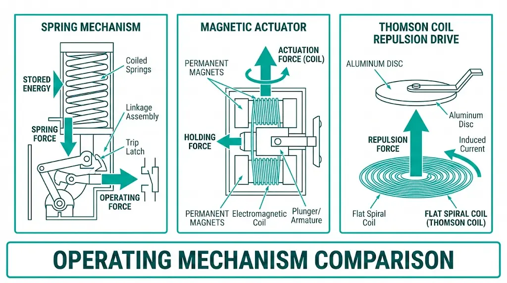
Three technologies dominate medium-voltage vacuum circuit breaker design today:
Selecting the wrong mechanism creates problems that surface years after commissioning. Understanding how vacuum circuit breakers work provides essential context for evaluating these options.
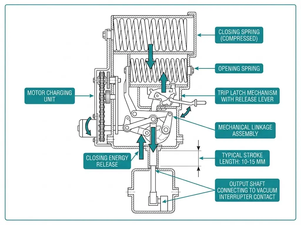
Spring-driven actuators remain the most widely deployed mechanism in vacuum circuit breakers rated 12–40.5 kV. The physics is straightforward: mechanical energy stored in pre-charged coil or disc springs converts to kinetic energy when a latch releases.
A typical 12 kV spring mechanism stores 180–220 J of potential energy. When the trip signal arrives, this energy drives contacts apart at velocities of 1.5–2.5 m/s. The mechanism follows Hooke’s law—force output remains proportional to spring displacement throughout the stroke.
Most designs employ separate closing and opening springs. The closing spring delivers high force to overcome contact wipe and the vacuum pressure differential acting on the bellows. The opening spring accelerates contact separation during fault interruption.
Typical specifications:
Advantages: Proven reliability spanning six decades. Energy independence—once charged, springs require no external power to complete a close-open-close cycle. Lower capital cost and global maintenance expertise.
Limitations: Mechanical complexity creates multiple wear points. Lubrication dependency at pivot points and sliding surfaces. The 30–60 ms opening time, while adequate for most applications, cannot match electromagnetic alternatives.
[Expert Insight: Spring Mechanism Field Observations]
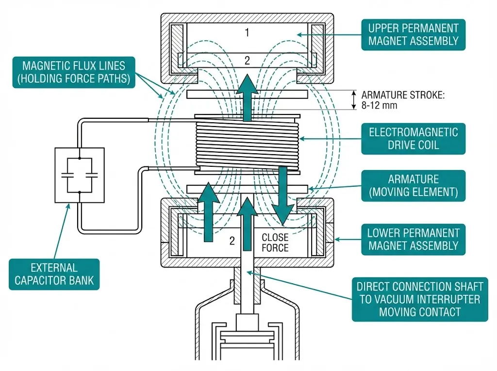
Permanent magnet actuators (PMAs) have gained significant adoption in modern VCB designs, particularly for frequent switching applications. These mechanisms eliminate mechanical latching entirely.
A permanent magnet—typically generating 0.8–1.2 T flux density—holds the armature in either the open or closed position. To change state, a capacitor bank discharges through an electromagnetic coil, creating a field that overcomes the permanent magnet’s holding force. The armature accelerates to the opposite position, where the permanent magnet again provides stable holding.
The armature connects directly to the vacuum interrupter’s moving contact. This direct-drive architecture eliminates the complex linkage systems required by spring mechanisms, reducing component count by approximately 60%.
Typical specifications:
Advantages: Reduced part count means fewer failure modes. No lubrication required—the absence of sliding mechanical linkages eliminates grease-dependent components. Faster opening speed improves arc energy limitation. Higher mechanical endurance suits high-switching applications.
Limitations: Capacitor bank dependency—electrolytic capacitors degrade over time, particularly above 40°C ambient. Higher capital cost (15–30% premium). Changing state requires charged capacitors, creating auxiliary power sensitivity.
Testing across mining installations with frequent load switching showed 15% faster total break times compared to equivalent spring units. For applications requiring magnetic actuator technology, XBRELE’s vacuum circuit breaker range includes multiple configurations.
[Expert Insight: Magnetic Actuator Deployment Lessons]
Thomson coil-based repulsion drives represent the fastest actuating technology available for vacuum circuit breakers. The physics exploits electromagnetic repulsion between parallel conductors carrying opposing currents.
A high-current pulse (typically 10–30 kA peak, lasting 1–2 ms) passes through a flat spiral coil. This rapidly changing field induces eddy currents in an adjacent aluminum disc. The induced currents create their own magnetic field, opposing the driving field. The result: intense repulsive force accelerating the disc—and the attached contact assembly—at rates exceeding 10,000 m/s².
Contact velocities of 5–20 m/s enable sub-20 ms total clearing times. Some repulsion-drive VCBs approach current-limiting performance typically associated with fuses.
Typical specifications:
Advantages: Ultra-fast interruption dramatically reduces arc energy. Near current-limiting performance protects sensitive downstream equipment. Compact form factor—the direct-drive architecture eliminates bulky spring assemblies.
Limitations: Narrow application window—primarily generator circuit breakers, high-speed transfer switches, and fault current limiters. Complex power electronics require factory support. Cost premium of 50–100% over spring mechanisms. Limited manufacturer availability complicates spare parts sourcing.
The following table summarizes key performance parameters. This comparison enables direct evaluation for specification purposes.
| Parameter | Spring Mechanism | Magnetic Actuator | Electric Repulsion |
|---|---|---|---|
| Contact velocity | 1.5–2.5 m/s | 2.0–3.0 m/s | 5–20 m/s |
| Opening time | 30–60 ms | 15–25 ms | 5–12 ms |
| Closing time | 50–80 ms | 40–60 ms | 15–25 ms |
| Mechanical endurance | 10,000 ops | 30,000–60,000 ops | 20,000–50,000 ops |
| Component count | 150–300 | 20–50 | 40–80 |
| Lubrication required | Yes | No | Minimal |
| Relative capital cost | 1.0× (baseline) | 1.15–1.30× | 1.50–2.00× |
| Maintenance interval | 2,000–5,000 ops | 10,000–20,000 ops | 5,000–10,000 ops |
| Auxiliary power dependency | Low | Medium | Medium-High |
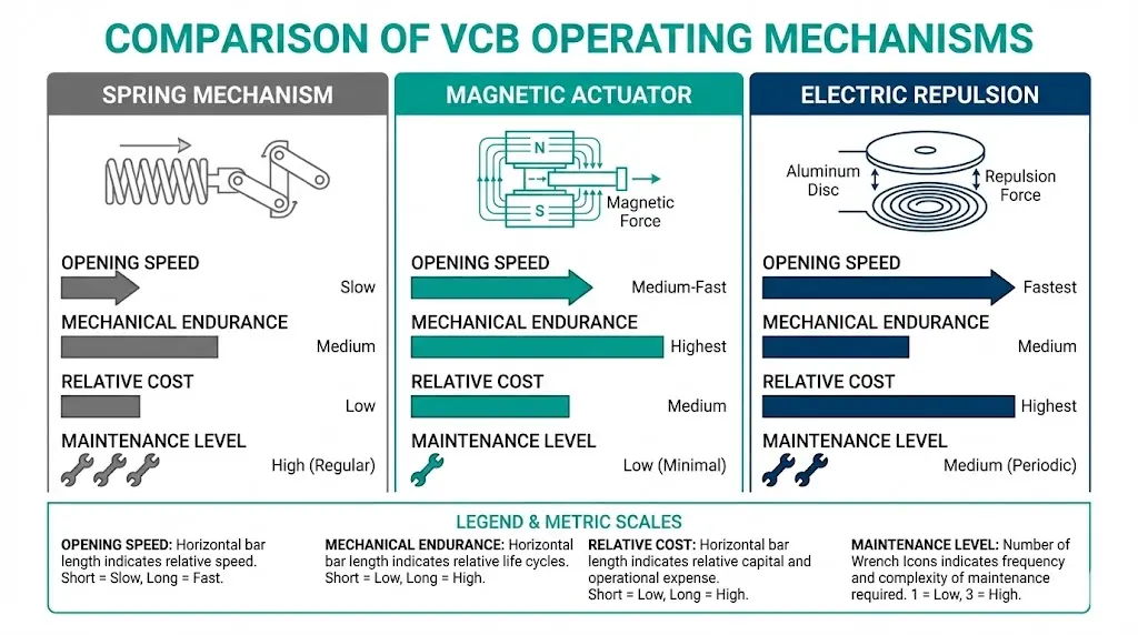
[FIG-03: Three-column comparison infographic displaying key performance metrics with visual indicators for speed, endurance, and cost positioning.]
The speed differential matters most during fault interruption. A magnetic actuator completing contact separation in 20 ms versus a spring mechanism at 45 ms reduces arc energy by over 50%—directly extending vacuum interrupter contact life.
Mechanism selection depends on switching duty, maintenance access, protection coordination requirements, and lifecycle cost expectations.
Choose Spring Mechanism When:
Choose Magnetic Actuator When:
Choose Electric Repulsion When:
The VCB RFQ checklist provides structured guidance for documenting mechanism requirements when engaging manufacturers.
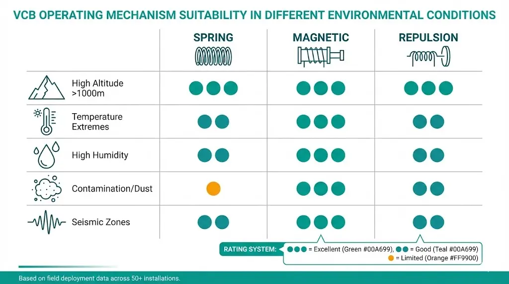
Operating mechanisms perform differently under real-world environmental stresses than laboratory conditions suggest.
Altitude Effects: Above 1,000 m, reduced air density affects spring mechanism lubrication—grease consistency changes as dissolved gases expand. Magnetic actuator capacitors experience reduced convective cooling. IEC 62271-1 specifies altitude correction factors, though field experience suggests conservative application above 2,500 m.
Temperature Extremes: Spring mechanisms in Arctic or desert installations require lubricants rated for the full operating range. Standard greases fail below -25°C or degrade rapidly above 55°C. Magnetic actuator capacitors may require heating provisions below -25°C to maintain adequate capacitance.
Contamination Resistance: Sealed magnetic actuators resist dust, humidity, and corrosive atmospheres better than spring mechanisms with exposed lubrication points. Industrial environments with airborne particulates favor magnetic actuator selection.
Seismic Qualification: Spring mechanisms with complex linkages require careful seismic qualification—each pivot point represents a potential failure under vibration. The simpler architecture of magnetic actuators often simplifies IEEE 693 seismic certification.
Maintenance Patterns: Spring mechanisms require periodic lubrication, linkage inspection, and timing verification. Magnetic actuators demand capacitor health monitoring but minimal mechanical intervention. Repulsion drives need power electronics diagnostics and occasional module replacement—typically requiring manufacturer support.
Operating mechanisms must satisfy type testing requirements per IEC 62271-100 for high-voltage switchgear and controlgear. Key test protocols include:
CIGRE Working Group A3.27 has published technical brochures examining actuator technology reliability across installed fleets, providing valuable reference data for utility engineers evaluating mechanism options.
No mechanism technology is universally superior. Spring systems deliver proven reliability at lower cost for standard switching duties. Magnetic actuators justify their premium through reduced maintenance and higher endurance in demanding applications. Electric repulsion drives occupy a specialized niche where ultra-fast interruption provides irreplaceable value.
Match mechanism technology to actual operating conditions, maintenance capabilities, and total cost of ownership—not theoretical specifications alone.
XBRELE offers vacuum circuit breakers with both spring and magnetic actuator options across 12 kV to 40.5 kV ratings. Contact our engineering team for mechanism selection guidance tailored to your specific application requirements.
Q: What is the primary difference between spring and magnetic actuator mechanisms in VCBs?
A: Spring mechanisms store mechanical energy in compressed springs and use 150–300 mechanical components with linkages, while magnetic actuators use electromagnetic force with permanent magnets and contain only 20–50 components—eliminating lubrication requirements and extending mechanical life to 30,000+ operations.
Q: Which VCB operating mechanism provides the fastest fault clearing?
A: Electric repulsion (Thomson coil) mechanisms achieve opening times of 5–12 ms with contact velocities of 5–20 m/s, approximately 3–5 times faster than spring mechanisms, though they carry significant cost premiums and limited availability.
Q: How often do magnetic actuator capacitors need replacement?
A: Electrolytic capacitors in magnetic actuators typically require replacement every 7–10 years under normal operating conditions, with accelerated degradation occurring in ambient temperatures consistently above 40°C or in high-humidity environments.
Q: Can spring-operated VCBs match the mechanical endurance of magnetic actuators?
A: Standard spring mechanisms are rated for 10,000 mechanical operations before requiring spring assessment and potential replacement, while magnetic actuators routinely achieve 30,000–60,000 operations—making magnetic actuators preferable for high-frequency switching applications.
Q: Do operating mechanism differences affect arc interruption capability?
A: Yes—faster contact separation reduces arc duration and total arc energy, which decreases contact erosion in the vacuum interrupter; a magnetic actuator achieving 20 ms opening versus 45 ms for a spring mechanism can reduce arc energy by over 50% per interruption.
Q: What environmental factors most affect mechanism selection?
A: Temperature extremes impact lubrication (spring) and capacitor performance (magnetic); altitude above 1,000 m affects both cooling and lubricant behavior; contaminated or corrosive atmospheres favor sealed magnetic actuators over spring mechanisms with exposed linkages.