Need Full Specifications?
Download our 2025 Product Catalog for detailed drawings and technical parameters of all switchgear components.
Get CatalogDownload our 2025 Product Catalog for detailed drawings and technical parameters of all switchgear components.
Get CatalogDownload our 2025 Product Catalog for detailed drawings and technical parameters of all switchgear components.
Get Catalog
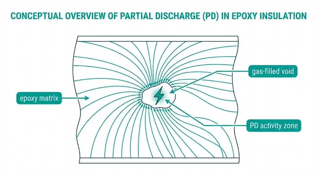
Partial discharge in epoxy insulation refers to localized electrical breakdown within gas-filled voids or defects that does not fully bridge the insulation between conductors. These micro-discharges release energy that progressively erodes the surrounding epoxy matrix, eventually creating conductive paths that compromise dielectric integrity.
Medium-voltage switchgear relies heavily on cast epoxy components: embedded poles housing vacuum interrupters, bushing insulators, current transformer enclosures, and structural supports. From the outside, these parts appear solid and uniform. Internally, however, manufacturing imperfections—entrapped air pockets, shrinkage cavities, interface delaminations—can harbor conditions that initiate PD at normal operating voltages.
The challenge for maintenance engineers and quality inspectors lies in detection. Partial discharge produces no visible external damage until failure is imminent. By then, carbonized tracking paths may have already developed within the epoxy bulk.
This article examines the physics behind PD initiation, identifies symptoms observable through various detection methods, and clarifies acceptance thresholds drawn from IEC and IEEE frameworks. Engineers specifying or inspecting vacuum circuit breaker assemblies will find practical guidance applicable from incoming component inspection through in-service monitoring.
Partial discharge in epoxy parts refers to localized electrical breakdown that occurs within or on the surface of epoxy insulation without completely bridging the electrodes. Unlike complete dielectric failure, PD activity remains confined to defect sites while surrounding insulation maintains its integrity. This localized ionization releases energy packets typically ranging from 1 pC to 1000 pC, depending on void size and applied voltage magnitude.
The physics centers on electric field enhancement at imperfections. When voltage stress exceeds the local dielectric strength—typically 3–5 kV/mm for air-filled voids—ionization begins. Field testing across medium-voltage switchgear installations rated 12–36 kV consistently shows that PD initiates at field intensities between 2–5 kV/mm within internal cavities, well below the 15–25 kV/mm breakdown threshold of solid epoxy itself.
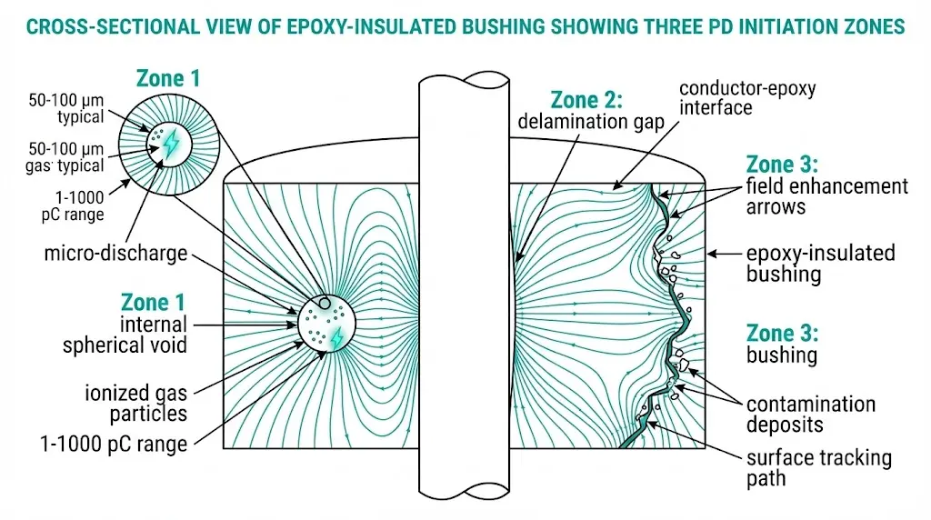
Three primary defect categories trigger partial discharge in epoxy insulation systems:
Internal voids and cavities form during casting when degassing is incomplete or when thermal cycling creates micro-separations between epoxy and embedded conductors. Gas-filled voids as small as 50 μm can initiate discharge activity because the dielectric strength of air (~3 kV/mm) is significantly lower than cured epoxy (~20–25 kV/mm).
Interfacial delamination develops where epoxy bonds to metallic inserts, bushings, or reinforcement materials. Differential thermal expansion coefficients between epoxy (approximately 50–70 × 10⁻⁶/°C) and copper conductors (17 × 10⁻⁶/°C) create mechanical stress that progressively separates these interfaces.
Surface contamination and tracking occurs when conductive deposits—moisture, dust, or chemical residues—create discharge paths along epoxy surfaces exposed to humid or polluted environments.
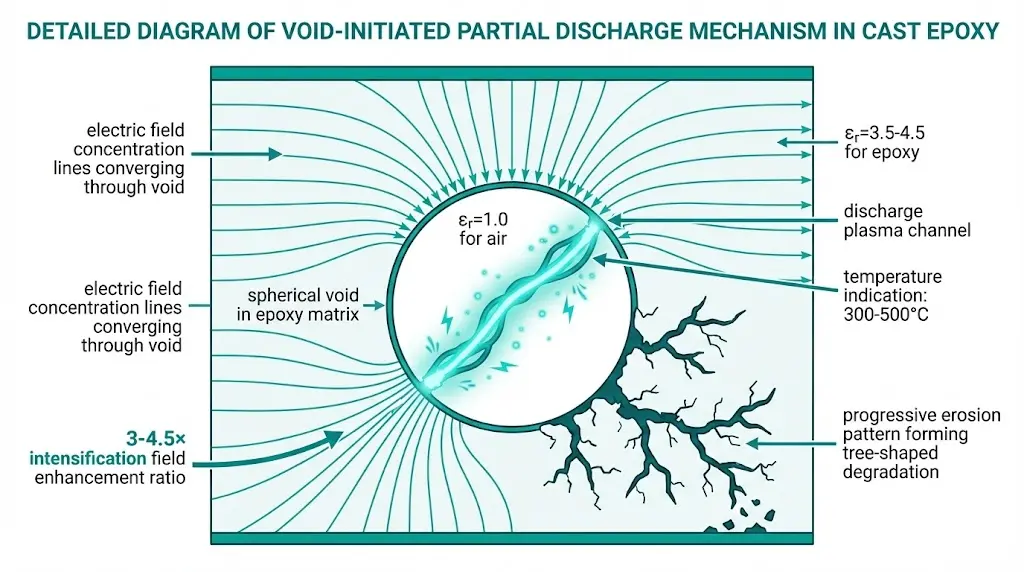
The partial discharge mechanism follows a predictable physics sequence. When alternating voltage is applied across epoxy insulation, any internal void experiences enhanced electric field concentration. A void’s relative permittivity (approximately 1.0 for air) compared to surrounding epoxy (εr ≈ 3.5–4.5) creates field enhancement ratios of 3× to 4.5× within the defect.
The discharge inception voltage follows the relationship where internal cavity stress = (εepoxy / εvoid) × applied field. When this localized stress exceeds approximately 3 kV/mm in air-filled voids at atmospheric pressure, Paschen breakdown occurs. Each discharge pulse typically releases 10-12 to 10-8 coulombs (1 pC to 10 nC), depending on void geometry and applied voltage magnitude.
Void sizes as small as 50–100 μm can sustain repetitive PD activity at operating frequencies of 50/60 Hz. Each AC cycle potentially triggers multiple discharge events—measurements show discharge repetition rates reaching 10³ to 10⁵ pulses per second under severe conditions.
The destructive cascade begins when repeated discharges erode surrounding epoxy material through ion bombardment, UV radiation, and localized heating reaching 300–500°C within the discharge channel. This creates progressive cavity enlargement, forming characteristic tree-shaped degradation patterns. Sustained PD activity above 1000 pC typically indicates accelerated insulation aging requiring maintenance intervention.
[Expert Insight: Field Observations on PD Progression]
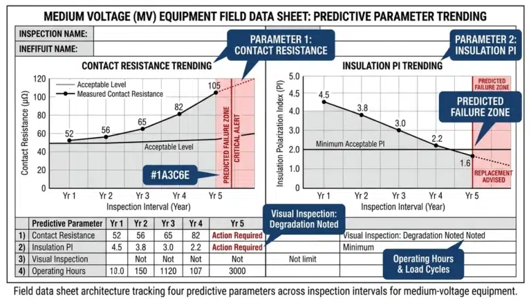
- Initial PD activity often appears stable for months before accelerating—regular trending reveals degradation before failure
- Thermal cycling between day/night operations accelerates interface delamination in outdoor installations
- Void-initiated PD in embedded poles typically progresses to tracking failure within 2–5 years if left unaddressed
- Contamination-driven surface PD responds well to cleaning, while internal voids require component replacement
Manufacturing process control directly determines void prevalence in cast epoxy components. Testing of over 200 cast resin transformer components reveals consistent patterns in defect formation.
Incomplete vacuum degassing leaves entrapped air bubbles, particularly in geometrically complex castings. Proper degassing requires maintaining vacuum levels below 1 mbar for 15–30 minutes before and during pour, depending on resin viscosity and component size.
Thermal gradient during cure creates shrinkage voids when outer surfaces solidify before internal regions. Thick-section castings exceeding 25 mm require controlled temperature ramping—typically 2–3°C per hour—to ensure uniform polymerization.
Inadequate mold release or surface preparation prevents proper wetting of embedded conductors and metallic inserts. Surface contamination with oils, oxides, or moisture creates interface defects that become delamination sites under thermal or mechanical stress.
Filler settling in filled epoxy systems occurs when silica or alumina particles separate before gelation. This creates density gradients with void-prone regions in upper casting sections.
| Defect Type | Root Cause | Typical Location | PD Risk Level |
|---|---|---|---|
| Shrinkage voids | Uneven cure temperature | Thick sections, geometric transitions | High |
| Entrapped air | Insufficient degassing time | Near conductors, sharp corners | High |
| Delamination | Poor surface preparation | Conductor-epoxy interface | Critical |
| Filler settling | Extended pot life, improper mixing | Upper casting portions | Medium |
| Moisture pockets | Contaminated materials, humid environment | Random distribution | Medium |
For vacuum circuit breaker manufacturers, embedded pole assemblies present particular challenges. The vacuum interrupter’s metal flanges, flexible conductor connections, and operating rod penetrations all create interfaces requiring precise epoxy encapsulation and validated surface preparation procedures.
Detection methodology selection depends on equipment accessibility, required sensitivity, and acceptable downtime.
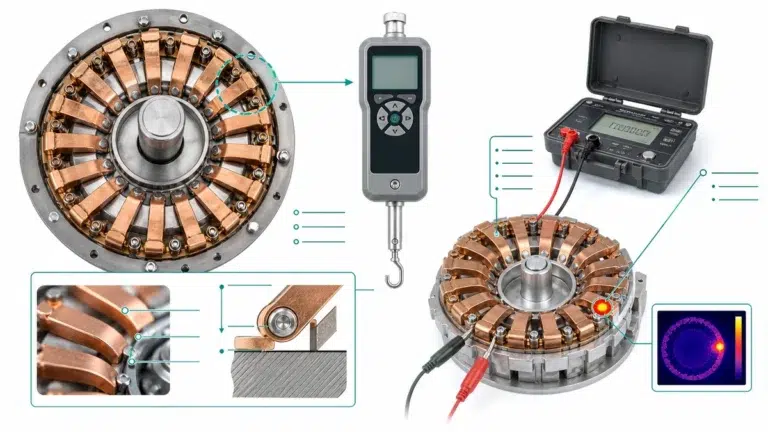
Electrical detection methods provide quantitative PD measurement:
Apparent charge measurement per IEC 60270 (High-Voltage Test Techniques – Partial Discharge Measurements) remains the reference standard for acceptance testing. Laboratory conditions achieve sensitivity of 1–5 pC using shielded test cells and low-noise amplifiers. Field measurements typically reach 10–50 pC sensitivity due to ambient electromagnetic interference.
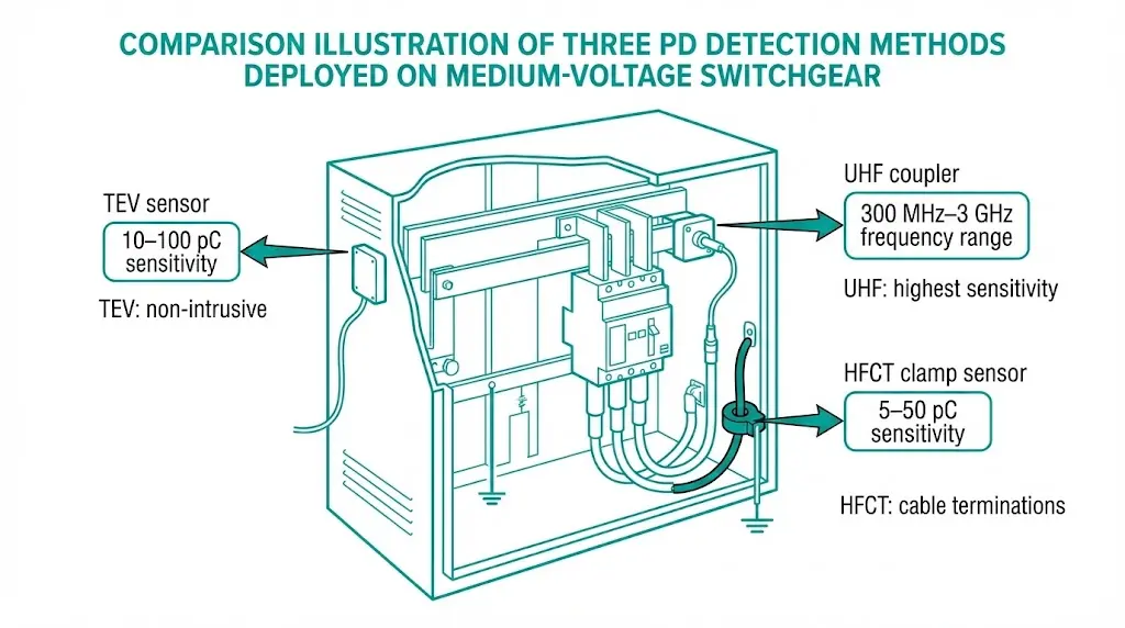
Ultra-high frequency (UHF) detection captures electromagnetic emissions in the 300 MHz–3 GHz range generated by rapid discharge current rise times. UHF methods excel in electrically noisy industrial environments where conventional 50/60 Hz measurements suffer interference. Metal-enclosed switchgear provides natural shielding that enhances UHF signal-to-noise ratios.
Acoustic emission sensing detects ultrasonic pulses (20–300 kHz) produced by gas expansion during discharge events. Triangulation using multiple sensors localizes PD sources within ±50 mm accuracy in accessible equipment.
Physical evidence becomes visible as PD activity intensifies:
Thermal signatures from infrared thermography reveal hot spots at discharge locations. Temperature elevations of 5–15°C above baseline warrant investigation, though deeply embedded defects may not produce detectable surface heating.
Offline testing during scheduled outages permits controlled voltage application and highest measurement sensitivity. Online monitoring detects trends without service interruption but operates at reduced sensitivity due to energized equipment noise.
Offline testing protocol:
Baseline measurement should occur within 6 months of installation for critical switchgear. Subsequent testing at 3–5 year intervals establishes degradation trends. Additional testing follows any thermal event, protection operation, or reported anomaly such as unusual sounds or odors.
Portable PD test systems with integrated coupling capacitors suit field deployment. Applied voltage typically follows IEC 60270 recommendations: conditioning at 1.1 × U₀ for 60 seconds followed by measurement at U₀ (phase-to-ground operating voltage). Background noise documentation validates measurement credibility.
Online monitoring technologies:
| Method | Sensitivity | Installation | Best Application |
|---|---|---|---|
| TEV (Transient Earth Voltage) sensors | 10–100 pC typical | Non-intrusive surface mount | Metal-clad/enclosed switchgear |
| UHF internal couplers | 1–10 pC achievable | Requires design integration or retrofit window | Critical loads, GIS |
| HFCT (High-Frequency Current Transformer) | 5–50 pC typical | Clamp-on earthing conductors | Cable terminations, bushings |
Continuous monitoring justifies investment for equipment serving critical loads where unplanned outages carry severe consequences. Integration with SCADA systems enables automated alarming when PD levels exceed trending thresholds.
Understanding vacuum interrupter construction helps prioritize monitoring—the interrupter itself operates in high vacuum immune to PD, but its epoxy encapsulation and external connections remain vulnerable.
[Expert Insight: Practical Detection Considerations]
- TEV sensors work best on painted or coated metal surfaces—bare metal provides inconsistent coupling
- UHF background noise mapping before commissioning establishes valid alarm thresholds
- Acoustic methods lose effectiveness through bolted joints and gaskets—sensor placement matters
- Combining two detection methods reduces false positive rates by 60–80% compared to single-method monitoring
IEC 62271-1 (High-voltage switchgear and controlgear – Common specifications) establishes PD testing requirements for medium and high-voltage equipment. The standard specifies type test methodology with acceptance threshold of ≤10 pC apparent charge measured per IEC 60270.
Test voltage sequence per IEC 62271-1:
Threshold hierarchy by test level:
| Test Level | Acceptance Limit | Application Context |
|---|---|---|
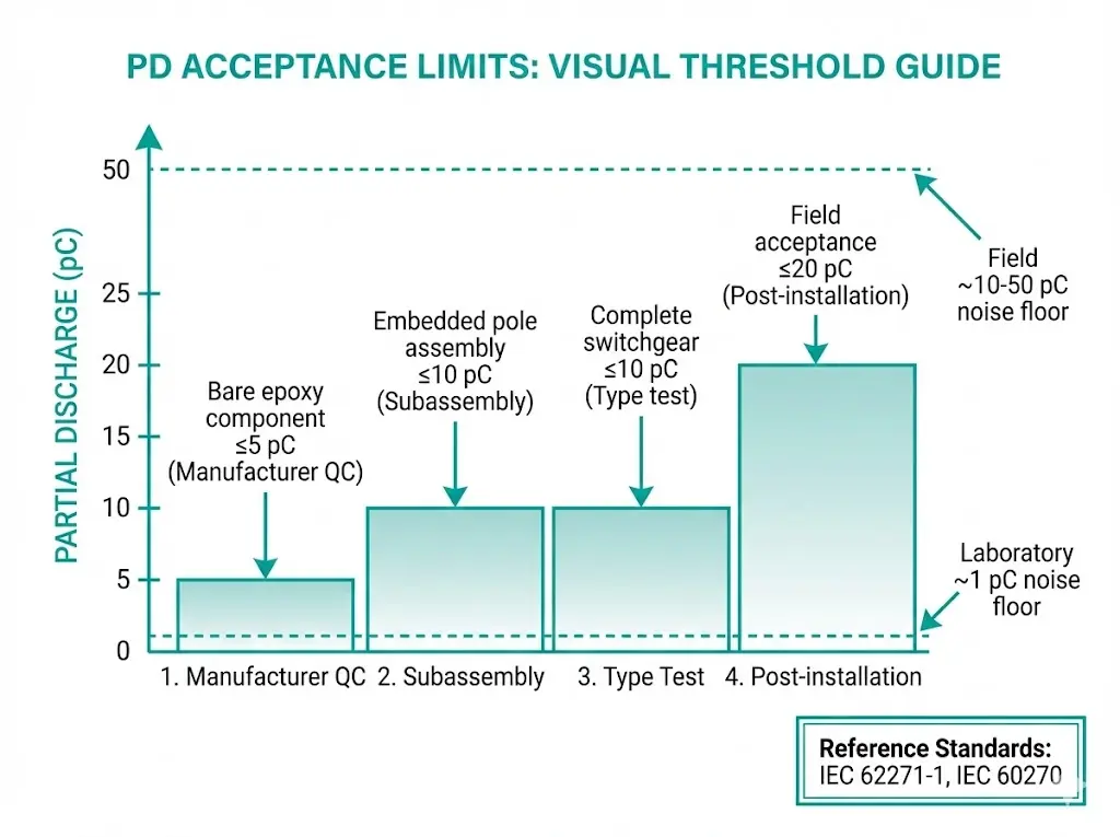
| Bare epoxy component | ≤5 pC | Manufacturer incoming QC |
| Embedded pole assembly | ≤10 pC | Subassembly verification |
| Complete switchgear | ≤10 pC | Type test, routine test if specified |
| Field acceptance | ≤20 pC | Post-installation (elevated noise floor) |
The conservative component-level threshold of ≤5 pC provides margin for additional interfaces and stress concentrations introduced during assembly integration. Components exceeding this limit warrant rejection or root-cause analysis before incorporation into switchgear assemblies.
IEEE C37.20.2 (Metal-Clad Switchgear) and C37.20.3 (Metal-Enclosed Switchgear) increasingly harmonize with IEC methodology and thresholds. Both standards reference IEC 60270 for measurement procedures and calibration requirements.
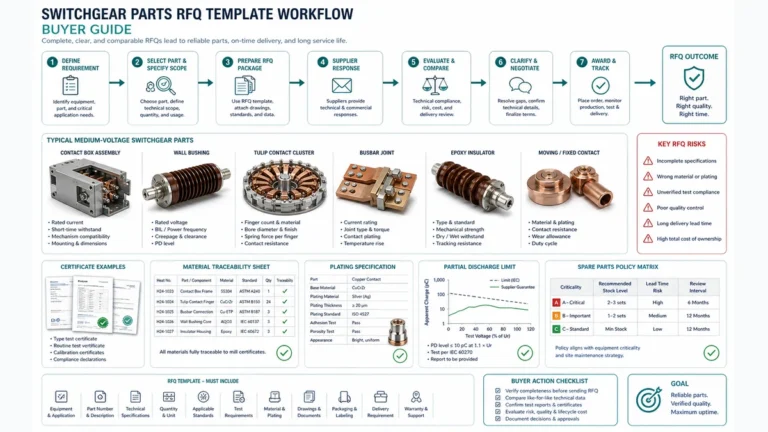
Effective procurement specifications establish clear requirements that suppliers can verify and document.
Essential RFQ requirements:
Supplier response red flags:
The VCB RFQ checklist provides comprehensive specification templates applicable to epoxy-encapsulated pole assemblies and associated switchgear components.
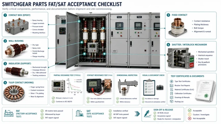
Incoming inspection protocol:
Visual examination identifies surface defects, contamination, and dimensional compliance. Dielectric testing per manufacturer’s routine test procedure—typically power frequency withstand for 1 minute—verifies basic insulation integrity. PD measurement during or after withstand testing confirms internal defect levels remain within specification.
Documentation retention should include test reports, calibration certificates, and material traceability records for warranty support and failure investigation if required during service life.
Partial discharge in epoxy insulation follows predictable physics: manufacturing voids concentrate electric fields, localized breakdown initiates at stress levels far below bulk material strength, and progressive erosion eventually defeats the dielectric barrier. Prevention starts with manufacturing discipline—vacuum casting under controlled conditions, proper degassing duration, validated interface preparation, and appropriate cure temperature profiles.
Detection combines acceptance testing during procurement with periodic field assessment and, for critical applications, continuous online monitoring. The ≤10 pC threshold for new MV equipment represents decades of industry experience codified in IEC standards.
For procurement, specify IEC 60270 compliance explicitly. Require manufacturing process documentation addressing void formation risks. Establish measurement baselines after installation and track trends over service life. When partial discharge activity appears—whether through electrical detection, physical evidence, or thermal imaging—investigate promptly. Early intervention prevents the catastrophic failures that follow unchecked PD progression.
Q: What causes partial discharge to start in epoxy insulation?
A: PD initiates when electric field stress within gas-filled voids or interface gaps exceeds approximately 3 kV/mm—the breakdown threshold of air. Manufacturing defects including entrapped bubbles, shrinkage cavities, and conductor delamination create these vulnerable sites.
Q: Can online monitoring replace periodic offline PD testing?
A: Online monitoring detects trending changes and acute events but typically operates at 5–10× lower sensitivity than controlled offline measurements. Most maintenance programs combine both approaches—continuous monitoring for early warning with periodic offline testing for quantitative assessment.
Q: How quickly does partial discharge damage epoxy insulation?
A: Progression varies widely based on discharge magnitude and repetition rate. Low-level activity (below 100 pC) may persist for years with minimal degradation, while sustained discharge above 1000 pC typically produces measurable erosion within months and tracking failure within 2–5 years.
Q: What PD level requires immediate action versus continued monitoring?
A: Readings below 20 pC in field conditions generally warrant continued monitoring at standard intervals. Levels between 20–100 pC suggest accelerated inspection frequency and root-cause investigation. Sustained activity above 100 pC typically requires planned replacement or repair within the next maintenance window.
Q: Does higher operating voltage always increase PD risk?
A: Higher voltage increases field stress proportionally, but insulation design should scale accordingly. A well-manufactured 36 kV component with proper clearances and void-free construction presents lower PD risk than a defect-laden 12 kV component operating near its design limits.
Q: Can partial discharge in epoxy be repaired without component replacement?
A: Surface tracking from contamination responds to cleaning and recoating. Internal voids and bulk defects cannot be repaired in service—affected components require replacement. Some manufacturers offer requalification testing after refurbishment, but this applies primarily to external surface restoration rather than internal defect remediation.
Q: Why do field PD measurements allow higher thresholds than factory tests?
A: Field environments introduce electromagnetic interference from operating equipment, reducing practical measurement sensitivity. The ≤20 pC field acceptance threshold accounts for this elevated noise floor while maintaining meaningful defect detection capability. Factory testing under controlled conditions achieves the ≤10 pC threshold specified for type tests.