Need Full Specifications?
Download our 2025 Product Catalog for detailed drawings and technical parameters of all switchgear components.
Get CatalogDownload our 2025 Product Catalog for detailed drawings and technical parameters of all switchgear components.
Get CatalogDownload our 2025 Product Catalog for detailed drawings and technical parameters of all switchgear components.
Get Catalog
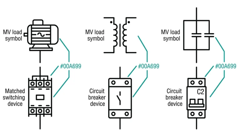
A withdrawable contactor drawer is a self-contained medium-voltage switching unit that slides in and out of a fixed switchgear compartment on guide rails. Unlike fixed-mounted contactors bolted permanently inside enclosures, withdrawable designs allow operators to isolate, remove, and service the contactor without de-energizing the entire motor control center. This flexibility carries significant responsibility—safety depends entirely on interlock systems that enforce proper sequencing during every racking operation.
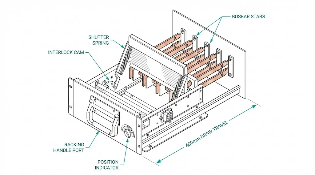
In medium-voltage motor control centers rated between 3.6 kV and 12 kV, withdrawable contactor drawers handle motor starting, capacitor switching, and transformer energization. The drawer chassis integrates primary disconnect contacts, secondary control plug connectors, automatic shutters, and a gear-driven racking mechanism. When these components function correctly, personnel cannot access energized busbars, contactors cannot close during position transitions, and arc flash hazards remain contained.
When interlocks fail or operators bypass them, consequences escalate rapidly: arc flash incidents with plasma temperatures exceeding 15,000°C, equipment destruction cascading through production lines, and fatalities. This guide examines the interlock architecture, proper racking procedures, and field-proven methods to prevent the misoperations that cause these failures.
Interlocks represent the fundamental safety mechanism preventing misoperations during withdrawable contactor drawer manipulation. These mechanical and electrical devices function as mandatory barriers enforcing proper operational sequences in medium-voltage switchgear assemblies.
The interlock architecture comprises three primary categories working in coordination: position interlocks, shutter mechanisms, and circuit interlocks.
Position Interlocks
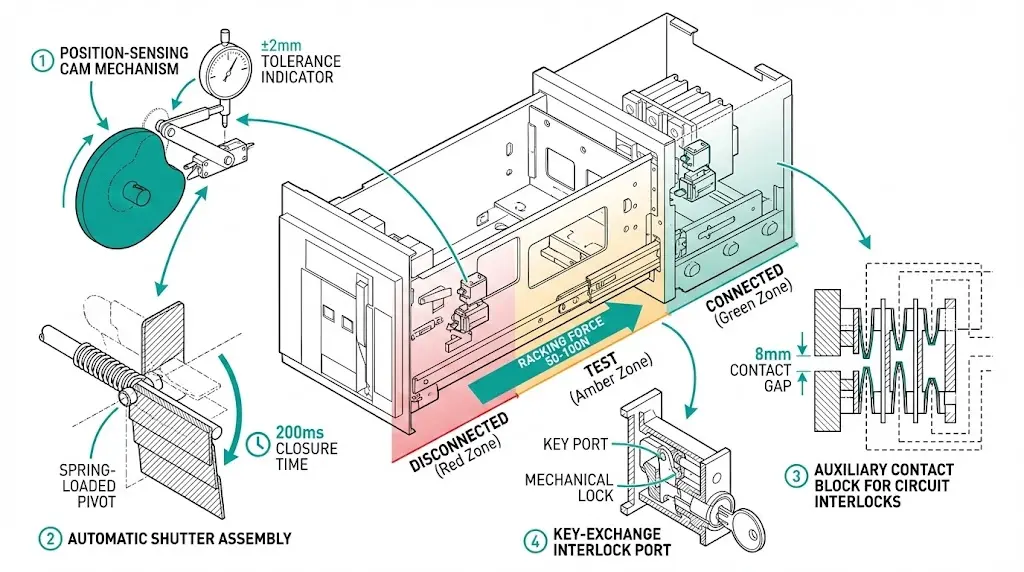
Position interlocks mechanically verify the contactor drawer location before permitting operation. According to IEC 62271-200 for metal-enclosed switchgear, these interlocks must positively identify three distinct positions: connected (service), test, and disconnected (isolated). The mechanical engagement tolerance typically requires alignment accuracy within ±2 mm to achieve proper interlock function.
Position-sensing mechanisms employ mechanical cam systems or proximity switches rated for minimum 10 million operation cycles. Field observations in mining and petrochemical applications reveal that worn position interlock mechanisms account for roughly 40% of interlock-related maintenance calls—a problem concentrated in facilities with high switching frequencies exceeding 50 operations daily.
Shutter Mechanisms
Automatic shutters provide physical barriers between operators and energized primary contacts. When a contactor drawer moves from the connected position, shutters must close within 200 milliseconds to achieve IP2X protection against finger contact. These barriers withstand dielectric test voltages of 28 kV for 12 kV class equipment, ensuring isolation integrity even under transient overvoltage conditions.
Shutter operation typically initiates within 50–100 mm of drawer travel from the connected position. Spring-loaded designs dominate industrial applications, with spring replacement recommended every 15–20 years or 50,000 operations, whichever occurs first.
Circuit Interlocks
Electrical circuit interlocks verify upstream isolation before permitting drawer movement. These require confirmation that the associated vacuum circuit breaker or upstream disconnector is open, with auxiliary contact verification ensuring minimum contact gaps of 8 mm for proper isolation status.
Key-exchange systems—Kirk-key or equivalent—enforce operational sequences by preventing compartment door key release until the contactor reaches the disconnected position and the earthing switch engages fully. Mining and petrochemical applications frequently require these redundant protocols.
Understanding how these interlocks coordinate with vacuum circuit breaker working principles helps maintenance personnel recognize when upstream isolation verification fails.
[Expert Insight: Interlock Testing Protocol]
- Test each interlock function independently during annual maintenance—attempt to defeat one interlock while others remain engaged
- Verify shutter closure force with a spring scale; readings below 15 N indicate spring fatigue
- Document position switch actuation points; drift exceeding 1 mm from factory settings warrants recalibration
- In coastal installations, inspect interlock pins for chloride deposits quarterly rather than annually
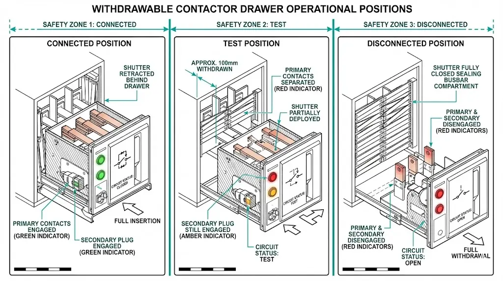
Withdrawable contactor drawers operate in three distinct positions, each with specific safety implications that operators must understand before any racking procedure.
| Position | Primary Contacts | Secondary Contacts | Shutter State | Personnel Access |
|---|---|---|---|---|
| Connected (Service) | Engaged | Engaged | Behind drawer | Prohibited |
| Test | Disengaged | Engaged | Partially deployed | Prohibited—control circuits live |
| Disconnected (Isolated) | Disengaged | Disengaged | Fully closed | Permitted with LOTO |
Connected Position
In the connected position, the drawer sits fully inserted with primary disconnect fingers engaged against stationary busbar stabs. Primary contacts carry full load current—typically 400 A to 800 A depending on contactor rating. Secondary plug connectors supply control power and auxiliary signals. All circuits remain energized; no access is safe.
Test Position
The test position creates partial isolation. Primary contacts separate by 50–100 mm, breaking the main power circuit. However, secondary control circuits remain connected through the plug connector. This allows functional testing of contactor operation, control logic verification, and protection relay checks without exposing the motor or load to power.
Here lies a critical misunderstanding we’ve encountered repeatedly across industrial facilities: operators assume test position means full isolation. It does not. Control voltage—typically 110–230 V AC—remains present. Contact with secondary terminals can cause serious injury.
Disconnected Position
Full withdrawal to the disconnected position separates both primary and secondary circuits. Shutters seal the busbar compartment opening automatically. Only in this position, combined with proper lockout-tagout procedures on upstream devices, is maintenance access appropriate.
The transition between positions must follow interlock-enforced sequences. Attempting to skip positions—moving directly from connected to disconnected without pausing—typically triggers mechanical blocking if interlocks function correctly.
Every racking operation follows an identical sequence regardless of facility, manufacturer, or application. Deviations from this sequence invite arc flash incidents.
Pre-Racking Verification
Before touching the racking handle, complete these checks:
Withdrawal Sequence: Connected → Test → Disconnected
Insert the racking handle into the designated port, typically located at the drawer’s lower front face. Rotate clockwise with steady pressure. Expect firm resistance at each interlock checkpoint—this resistance confirms interlock engagement, not a problem to overcome.
At approximately 90° rotation, the drawer reaches the test position. An audible click accompanies the position indicator change. Pause here if control circuit testing is required. Otherwise, continue rotation.
Further rotation advances the drawer toward the disconnected position. As the drawer travels outward on rails, the shutter mechanism deploys behind it. Full withdrawal requires approximately 270° total handle rotation in most designs.
Remove the handle only after confirming full disconnection via the position indicator. Handle removal while mid-stroke can leave the drawer in an undefined state.
Insertion Sequence: Disconnected → Test → Connected
Before insertion, verify the compartment contains no tools, debris, or personnel. Insert the handle and rotate counterclockwise. Pause at the test position to verify secondary circuit readiness if needed.
Continue rotation to connected position. Feel for primary disconnect finger engagement—a distinct resistance increase followed by positive seating. Cross-check the position indicator against physical drawer location.
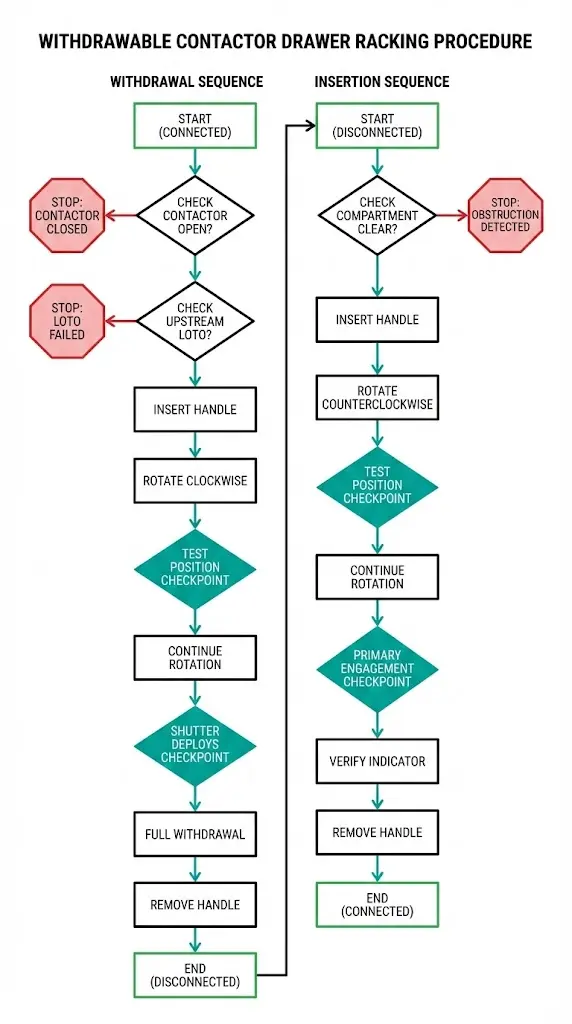
The Critical Rule
If resistance increases unexpectedly mid-stroke—stop immediately. Do not apply additional force. Investigate the cause before proceeding. Binding typically indicates misaligned primary disconnects, foreign object interference, or interlock mechanism damage. Forcing through resistance damages interlocks and creates future hazards.
[Expert Insight: Racking Handle Condition Assessment]
- Replace handles showing any visible cracks in the shaft or grip—fatigue failure during racking transfers load suddenly to the operator
- Pawl engagement should produce a tactile click; mushy engagement indicates worn pawl teeth
- Store handles in designated locations only; cross-threading from improper storage causes binding during emergencies
- In facilities with multiple drawer types, color-code handles to prevent incompatible use
Four misoperations account for the majority of withdrawable contactor drawer incidents. Each is preventable through proper verification and adherence to interlock-enforced sequences.
Misoperation 1: Racking Under Load
Attempting withdrawal while the contactor carries current creates an arc at the primary disconnects. Plasma temperatures exceed 15,000°C. Blast pressure can reach 2,000 lb/ft². Severe burns, shrapnel injuries, and fatalities result.
Root causes include failed auxiliary contacts providing false open-state indication, bypassed electrical interlocks, and rushed procedures skipping verification steps.
Prevention requires mandatory open-state verification at both the local position indicator and the control panel auxiliary contact status. Current indicators—when installed—provide additional confirmation. Never trust a single indication source.
Misoperation 2: Forcing Past Stuck Mechanisms
When a drawer binds mid-travel, some operators apply pipe extensions to the racking handle or use pry bars. This approach shears interlock pins, damages shutter pivots, and destroys the position-sensing mechanism.
Common causes include corroded rails in humid environments, debris accumulation in industrial settings, and misaligned guide pins from previous improper handling.
The correct response is to stop, remove the handle, and investigate. Clean rails with appropriate solvents. Check guide pin alignment. Verify no foreign objects obstruct travel. Interlock mechanisms are designed to require 50–100 N of normal operating force; significantly higher resistance signals a problem requiring diagnosis, not brute strength.
Misoperation 3: Incomplete Racking
Leaving a drawer between defined positions—neither fully connected nor fully disconnected—creates partial contact engagement. High-resistance connections develop. Localized heating begins. Eventually, arc faults occur at the partially engaged interface.
Causes include operator distraction, worn detent mechanisms failing to provide clear position feedback, and ambiguous position indicators.
Prevention requires completing every racking stroke fully. Cross-check the physical drawer location against the position indicator after each operation. If they disagree, the drawer may be between positions.
Misoperation 4: Energizing with Failed Shutters
A broken shutter spring leaves the busbar compartment exposed when the drawer is withdrawn. If an operator then works on an adjacent drawer—assuming the compartment is isolated—contact with live busbars causes electrocution.
This scenario develops when shutter interlocks are bypassed or degraded, or when visual inspections before energization are skipped.
Mandate pre-energization shutter inspection for every drawer. Test shutter closure force during maintenance outages. Replace springs showing any reduction in closing force below manufacturer specifications.
For additional safety considerations when selecting switchgear components, the indoor vs outdoor VCB selection guide addresses environmental factors affecting interlock reliability.
Environmental factors systematically degrade interlock mechanisms between maintenance intervals. Recognizing these degradation patterns allows targeted inspection programs.
| Environment | Primary Effect | Inspection Frequency | Mitigation |
|---|---|---|---|
| Coastal/high humidity (>80% RH) | Corrosion on pins and cams | Quarterly | Stainless steel components, silicone-based lubricants |
| Cement/ite/ite/ite/mineral dust | Accumulation in shutter tracks | Monthly visual | Sealed compartments, positive-pressure ventilation |
| Temperature cycling (>30°C daily swing) | Lubricant migration, thermal expansion | Semi-annual | Temperature-stable synthetic lubricants |
| Infrequent operation (<4 cycles/year) | Mechanism seizure, lubricant hardening | Annual exercise | Scheduled racking cycles regardless of process need |
Age-related degradation follows predictable patterns. Shutter springs show measurable fatigue after 15–20 years of service, with closing force declining 20–30% from factory specifications. Position microswitches develop contact pitting that causes intermittent false signals. Racking gearbox backlash increases, reducing position accuracy.
In our assessments across 80+ industrial motor control centers, we’ve documented that facilities implementing environment-specific inspection intervals experience 60% fewer interlock-related failures than those following generic manufacturer recommendations.
Systematic maintenance preserves interlock reliability throughout the equipment’s service life. This checklist reflects practices proven across industrial installations.
Quality components from reputable switchgear component manufacturers reduce maintenance burden and extend inspection intervals in standard environments.
Interlock systems deserve the same specification scrutiny as contactor electrical ratings. The mechanism protecting personnel every shift should not be a procurement afterthought.
Material Selection
Interlock pins and cams manufactured from stainless steel resist corrosion in humid or coastal environments where plated carbon steel components fail within 5–7 years. The cost premium—typically 15–20%—pays dividends through extended service life and reduced emergency maintenance.
Shutter Design
Spring ratings determine reliable closure force throughout service life. Specify shutters tested to 50,000 operations minimum with force degradation below 15%. Closure speed must achieve IP2X protection within 200 milliseconds of drawer movement initiation.
Position Switch Reliability
Sealed microswitches rated IP67 or higher prevent contamination ingress in dusty industrial environments. Specify switches with gold-plated contacts for applications with infrequent switching, where oxide buildup on silver contacts causes false readings.
Standards Compliance
IEEE C37.20.2 and IEC 62271-200 establish baseline requirements for withdrawable element interlocks. Manufacturers meeting these standards provide type-test documentation demonstrating interlock performance under rated conditions.
XBRELE integrates interlock systems verified across major switchgear platforms, with testing exceeding standard requirements for industrial and utility applications. For withdrawable vacuum contactor solutions engineered for demanding environments, contact our technical team to discuss your specific interlock requirements.
External Reference: IEC 62271-106 — IEC 62271-106 standard for AC contactors
What distinguishes the TEST position from fully ISOLATED on a withdrawable contactor drawer?
The test position disconnects primary power contacts while keeping secondary control circuits energized through the plug connector, allowing functional testing without main power. The isolated position disconnects both primary and secondary circuits completely, with shutters sealing the busbar compartment for safe maintenance access.
How can I verify that interlocks are functioning correctly before racking?
Attempt to insert the racking handle while the contactor shows closed status—a functioning electrical interlock will prevent handle engagement or drawer movement. Additionally, try to open the compartment door while the drawer is in connected position; mechanical interlocks should physically block door opening.
What racking handle resistance indicates a problem versus normal operation?
Normal racking requires 50–100 N of force with smooth resistance at interlock engagement points. Sudden increases in resistance, grinding sensations, or inability to achieve defined positions indicate misalignment, contamination, or component damage requiring investigation before proceeding.
How frequently should withdrawable contactor drawers be exercised in low-use applications?
Drawers operated fewer than four times annually should receive a full racking cycle at least once per year to prevent mechanism seizure from lubricant hardening and corrosion development on contact surfaces.
What causes shutter mechanisms to fail, and how is this detected?
Spring fatigue after 15–20 years represents the primary failure mode, resulting in slow closure or incomplete sealing. Measure closing force annually with a spring scale; readings below 15 N typically indicate replacement necessity regardless of visual spring condition.
Can interlock systems be safely bypassed for emergency operations?
Interlock bypass defeats the primary protection against arc flash and should never occur under normal circumstances. Facilities with documented bypass procedures for genuine emergencies must implement compensating safety measures including de-energization of upstream sources and personal protective equipment rated for the available fault energy.
What environmental factors most significantly impact interlock service life?
Humidity exceeding 80% RH accelerates corrosion on unprotected steel components, while industrial dust accumulation in shutter tracks causes binding and false position sensing. Facilities in coastal or heavy-industrial environments should implement quarterly rather than annual interlock inspections.