Need Full Specifications?
Download our 2025 Product Catalog for detailed drawings and technical parameters of all switchgear components.
Get CatalogDownload our 2025 Product Catalog for detailed drawings and technical parameters of all switchgear components.
Get CatalogDownload our 2025 Product Catalog for detailed drawings and technical parameters of all switchgear components.
Get Catalog
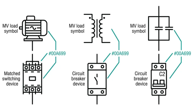
A contactor failure at 2 AM means one thing: production stops until you fix it. This field cheat sheet eliminates guesswork—each symptom links directly to probable causes and actionable fixes. Whether diagnosing a chattering coil, welded contacts, or a vacuum contactor that refuses to interrupt, use this guide as your MCC room companion.
The approach works for both low-voltage contactors (IEC 60947-4-1) and medium-voltage vacuum contactors (IEC 62271-106). Bookmark it. Print it. Keep it in your tool bag.
Contactors fail through three distinct pathways: electrical degradation, mechanical wear, and environmental attack. Recognizing which category applies accelerates diagnosis and prevents wasted effort.
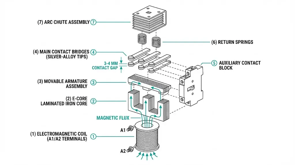
The coil and contacts bear the highest stress. Coils fail from thermal overload—repeated energization cycles generate heat that degrades winding insulation until turns short or the conductor opens entirely. Main contacts erode with each switching operation as arc energy vaporizes surface material. Modern contactors employ silver-based materials—typically AgCdO or AgSnO₂—that withstand arc erosion, but after thousands of operations, contact thickness depletes below functional limits.
Contact resistance provides critical diagnostic data. New silver-alloy contacts typically exhibit resistance below 50 μΩ, while contacts approaching end-of-life often measure 200–500 μΩ or higher. This resistance increase reflects material loss from arc erosion, where each switching operation removes 10-8 to 10-6 grams of contact material depending on current magnitude and arc duration.
Control circuit faults mimic contactor failure without damaging the contactor itself. Open interlocks, blown control fuses, and failed PLC outputs all produce identical symptoms.
Moving parts wear. Armature pivot points develop play, reducing magnetic circuit efficiency. Closing and opening springs lose tension through fatigue. Toggle linkages in larger contactors accumulate wear at pin joints, eventually causing binding or misalignment.
High temperatures increase coil resistance and soften contact materials. Humidity promotes corrosion on auxiliary contacts. Coastal installations face salt fog that attacks exposed surfaces. Industrial environments introduce conductive dust—metal particles, carbon, cement powder—that tracks across insulation and contaminates contact faces.
From testing data across mining and manufacturing installations, thermal factors cause approximately 25% of premature failures—typically when ambient temperatures exceed the 40°C rating common to most industrial contactors.
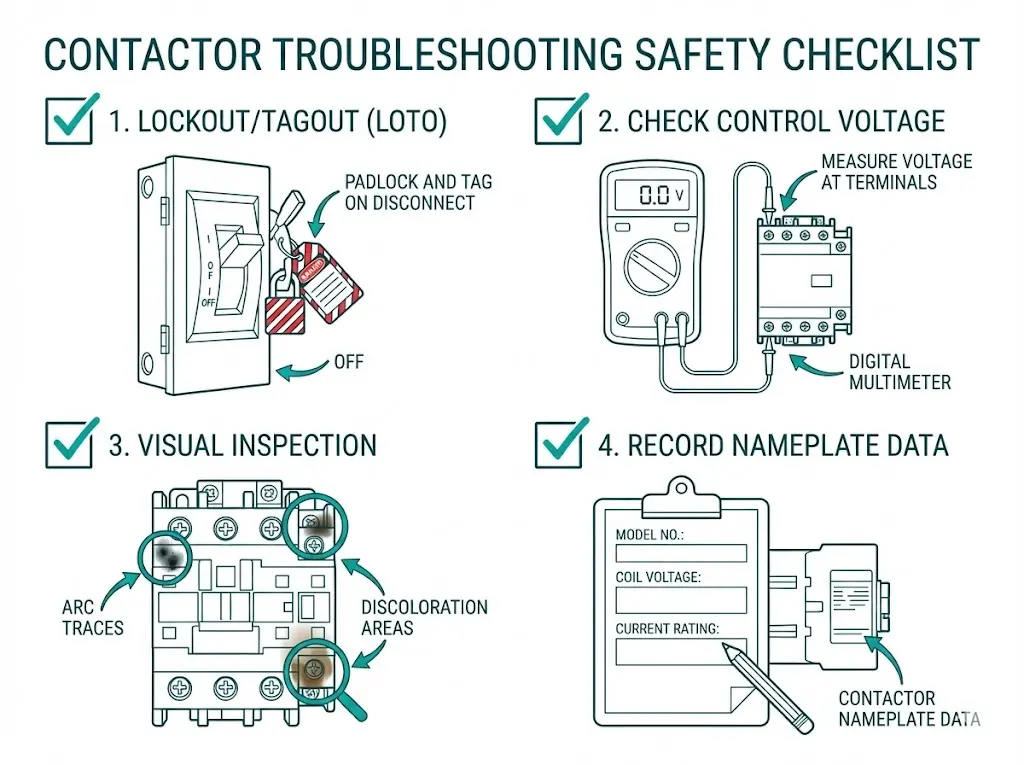
Before touching any contactor, complete these baseline verifications. Skipping them wastes time and risks misdiagnosis.
Verify isolation of both power and control circuits. Control voltage can remain energized even when main power is isolated—a common oversight that causes unexpected contactor operation during testing.
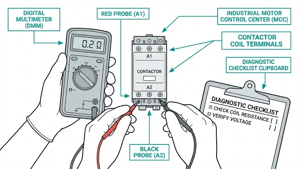
Measure voltage directly at coil terminals A1-A2. According to IEC 60947-4-1, contactors must operate reliably at 85% of rated coil voltage. Below this threshold, electromagnetic pull weakens, causing contact chatter and accelerated arc erosion. Voltage should fall within ±10% of nameplate rating.
Check for arc traces on contact surfaces, discoloration indicating overheating, mechanical obstructions, and pest intrusion. Record nameplate data: coil voltage, utilization category (AC-3, AC-4), and rated operational current.
Note ambient temperature, humidity levels, and contamination sources. These factors influence which failure modes to prioritize during diagnosis.
Field Reality: Approximately 70% of “failed contactor” service calls trace to control circuit issues—not the contactor itself. Verify voltage first.
[Expert Insight: Control Circuit Diagnostics]
This table covers the eight most common contactor failure symptoms encountered in field service. Start here for rapid diagnosis.
| Symptom | Probable Causes | Corrective Actions |
|---|---|---|
| Won’t pull in (no armature movement) | Open control circuit or blown fuse; Coil open-circuit failure; Mechanical jam or foreign object; Interlock contact blocking | Trace control wiring continuity; Measure coil resistance vs. spec; Check mechanism travel manually; Verify interlock status |
| Pulls in but immediately drops out | Seal-in auxiliary contact (13-14) not closing; Voltage sag during inrush; Worn auxiliary contact block | Check holding circuit wiring; Verify supply capacity; Replace auxiliary block |
| AC coil buzzes or hums loudly | Shading ring cracked or missing; Armature pole face contaminated; Control voltage below 85% nominal | Replace shading coil assembly; Clean pole faces with approved solvent; Correct supply voltage |
| Main contacts welded shut | Locked rotor or downstream short circuit; Contact erosion beyond limit; Contactor undersized for duty | Clear load-side fault first; Replace contact kit; Reselect contactor rating |
| Rapid chattering (make-break cycling) | Unstable control voltage; Return spring weakened; Control logic oscillation | Stabilize voltage supply; Replace spring mechanism; Review control schematic |
| Excessive contact erosion | Operating beyond rated category; Frequent jogging duty; Poor contact alignment | Match contactor to actual duty cycle; Add soft starter or VFD; Realign contact carrier |
| Auxiliary contacts unreliable | Surface oxidation; Insufficient contact wipe; Loose terminal connections | Burnish with contact file (not sandpaper); Inspect linkage adjustment; Retorque terminals |
| Terminal overheating | Loose connections; Undersized conductors; High ambient temperature | Retorque all terminals to manufacturer spec; Verify conductor sizing; Improve enclosure ventilation |
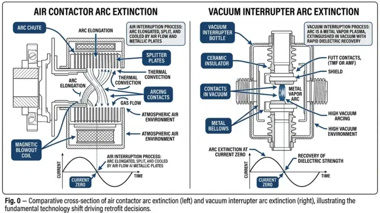
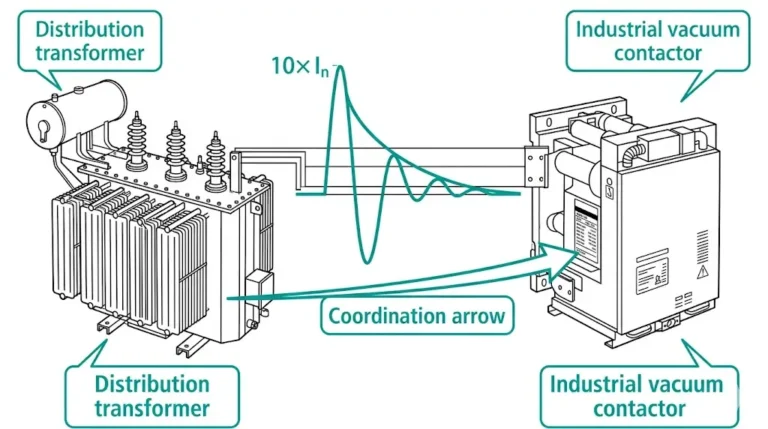
Welded contacts indicate the contactor interrupted current beyond its rated breaking capacity, or a downstream fault persisted through multiple operations. For standard air-break contactors, the contact kit may be replaceable if the carrier and arc chutes remain undamaged. For vacuum contactors, welded contacts inside the interrupter bottle cannot be field-repaired—complete vacuum interrupter replacement is required.
The coil represents approximately 35% of contactor failures in our field service records. Systematic electrical testing pinpoints the failure mode.
Disconnect control wiring and measure coil resistance between terminals A1 and A2:
Critical operating parameters include: pickup voltage ≥ 85% of rated coil voltage (Us), dropout voltage ≤ 20% of Us, and mechanical endurance ratings typically exceeding 10 × 106 operations for properly maintained units.
At rest, an AC contactor coil presents low impedance (approximately 10-50 Ω for typical industrial sizes), drawing inrush current 6-10 times steady-state for 50-100 milliseconds. Once the armature closes, reduced air gap increases inductance, dropping current to holding levels of 0.2-0.5 A. Mechanical jamming that prevents closure keeps the coil in high-current mode—thermal failure follows within seconds.
AC contactors require a shading ring (copper band) on the pole face to prevent 100/120 Hz buzz. When this ring cracks or falls off, the armature vibrates audibly at twice line frequency. Replacement requires partial disassembly but restores quiet operation.
DC coils with electronic economizer circuits show different characteristics. The economizer reduces holding current by 70-80% through PWM switching. Disconnect the economizer before measuring static resistance, or readings will mislead.
Medium-voltage vacuum contactors present unique diagnostic challenges. The contacts operate inside a sealed vacuum interrupter—visual inspection is impossible.
When vacuum degrades, symptoms appear during interruption:
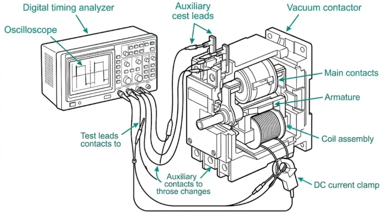
Apply AC withstand voltage across open contacts using a hi-pot tester. For 7.2 kV class vacuum contactors, typical test voltage ranges from 20-32 kV for one minute [VERIFY STANDARD: IEC 62271-106 routine test voltage requirements]. Breakdown or excessive leakage current indicates vacuum loss requiring interrupter replacement.
Since vacuum interrupter contacts cannot be visually inspected, track erosion indirectly:
Most vacuum contactors achieve 100,000 to 1,000,000 mechanical operations depending on rated class, though electrical endurance varies with interrupted current magnitude.
[Expert Insight: Vacuum Contactor Maintenance]
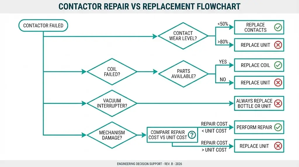
Not every failure justifies full replacement. This decision framework balances repair cost against reliability risk.
| Condition | Repair Viable | Replace Recommended |
|---|---|---|
| Contact wear < 50% remaining | ✓ Install contact kit | — |
| Contact wear > 80% depleted | — | ✓ Replace contactor |
| Coil failure (parts available) | ✓ Replace coil | — |
| Vacuum interrupter compromised | — | ✓ Replace bottle or unit |
| Mechanism damage (springs, linkages) | Evaluate parts cost | Often more economical to replace |
| Arc chute damage (air-break) | ✓ Replace arc chute | — |
| Housing cracked or deformed | — | ✓ Replace unit |
| Model obsolete (no spare parts) | — | ✓ Replace with equivalent |
Hidden Cost Considerations
Repair labor often exceeds component cost. A coil replacement requiring four hours of electrician time may cost more than a new contactor—particularly for smaller frame sizes. Factor in production downtime risk: a repaired contactor that fails again next month costs far more than the initial replacement premium.
For critical switchgear applications, maintaining spare contactors eliminates repair-time pressure entirely. Swap the failed unit, restore production, then repair or dispose of the removed contactor during scheduled maintenance windows.
When replacement becomes the right choice, contactor selection directly impacts future reliability. XBRELE manufactures vacuum contactors and switchgear components engineered for demanding industrial environments—mining operations, water treatment facilities, and heavy manufacturing where failure costs multiply quickly.
Our vacuum contactor product line features:
Technical support includes application engineering assistance for proper contactor sizing—preventing the undersizing failures that cause premature contact welding. Spare parts availability ensures your maintenance inventory stays current even for extended equipment lifecycles.
Contact XBRELE engineering for contactor selection guidance or replacement quotations.
External Reference: IEC 62271-106 — IEC 62271-106 standard for AC contactors
A: AC contactors buzz when the shading ring is cracked or missing, preventing the armature from seating firmly against the magnetic core. Contamination on the pole faces creates the same symptom by introducing an air gap in the magnetic circuit.
A: Contact welding results from interrupting current beyond the contactor’s rated breaking capacity or from downstream faults that cause prolonged arcing. Undersized contactors operating near their limits weld more frequently than properly rated units.
A: Measure resistance between terminals A1 and A2 with control wiring disconnected. Compare the reading to manufacturer specifications—infinite resistance indicates an open winding, while values significantly below spec suggest shorted turns from insulation breakdown.
A: No. Vacuum contactor contacts are sealed inside the interrupter bottle under high vacuum. Field repair requires complete vacuum interrupter replacement, not individual contact servicing.
A: The seal-in auxiliary contact (typically terminals 13-14) is failing to close and maintain the control circuit. Alternatively, control voltage may sag below the 85% pickup threshold during the initial inrush period.
A: Mechanical endurance typically ranges from 100,000 to 1,000,000 operations depending on frame size and manufacturer design. Electrical endurance depends heavily on interrupted current—fault interruptions consume significantly more contact material than normal load switching.
A: Measure control voltage at the coil terminals during the energization attempt. Low or absent voltage causes most apparent contactor failures—the contactor itself is often functional.