Need Full Specifications?
Download our 2025 Product Catalog for detailed drawings and technical parameters of all switchgear components.
Get CatalogDownload our 2025 Product Catalog for detailed drawings and technical parameters of all switchgear components.
Get CatalogDownload our 2025 Product Catalog for detailed drawings and technical parameters of all switchgear components.
Get Catalog
A 6.6 kV crusher motor feeder tripped on overcurrent. The protection system worked—partially. One HRC fuse cleared a phase-to-ground fault in under 15 milliseconds. The other two fuses remained intact. So did the contactor.
What followed was predictable to anyone who has investigated single-phasing failures: the motor continued running on two phases, drawing 175% rated current through an unbalanced winding configuration. Negative-sequence currents heated the rotor cage unevenly. Within four minutes, the motor’s thermal protection finally tripped—but not before insulation damage had shortened the stator’s remaining service life by an estimated 40%.
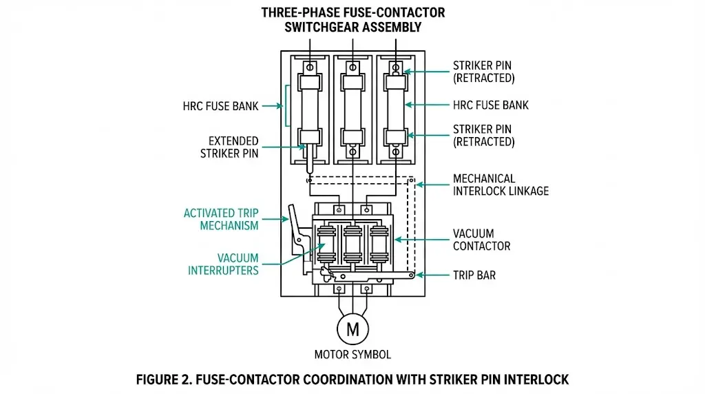
Post-event analysis identified two failures. The operated fuse’s striker pin had extended correctly, but corrosion in the interlock linkage pivot prevented the trip bar from rotating fully. The contactor latch never released. Additionally, the coordination study completed during commissioning had never verified striker-to-interlock mechanical function—only the electrical protection curves.
Fuse-contactor switchgear remains one of the most economical protection schemes for medium-voltage motor feeders. The combination leverages what each device does best: the HRC fuse provides current-limiting fault interruption; the vacuum contactor handles thousands of load switching operations without contact degradation. Between them, the striker pin and interlock mechanism form a critical but often overlooked link.
This article examines that link in detail—how striker trip mechanisms operate, what interlock design options exist, and the coordination pitfalls that transform a sound protection philosophy into a field failure.
F-C switchgear combines high-rupturing-capacity (HRC) fuses with vacuum contactors to protect medium-voltage motors and transformer circuits. The fuse handles short-circuit interruption through current-limiting action; the contactor manages normal switching duties and provides three-phase isolation after any fuse operates.
This division of protective duties defines the arrangement’s efficiency. Vacuum contactors in F-C combinations typically break 2–8 kA, while associated HRC fuses interrupt fault currents reaching 50 kA or higher. The contactor never sees fault current directly—the fuse clears the fault first, and the contactor opens into a de-energized circuit.
The coordination requirement is straightforward: when a fault operates one or more fuses, the contactor must open all three phases to prevent single-phasing. A motor running on two phases draws negative-sequence current that heats rotor bars unevenly. Under full-load conditions, winding damage can begin within 2–5 seconds.
IEC 62271-106 governs AC contactors above 1 kV, establishing type test requirements for short-circuit withstand. IEC 60282-1 covers high-voltage fuse design and performance.
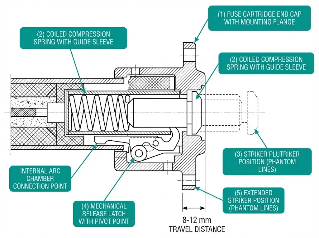
The striker pin is a spring-loaded plunger housed within the HRC fuse cartridge end cap. Its function is purely mechanical: translate fuse operation into a physical displacement that triggers the interlock system.
The critical timing point: striker extension occurs after the fuse has interrupted the fault. The contactor opens into a circuit that the fuse has already de-energized. This sequencing is not a limitation—it is the fundamental design principle. The fuse does the heavy lifting; the contactor provides visible isolation and prevents single-phasing.
Internal gas pressure during arc extinction typically reaches 2–4 bar, providing the force that releases the striker latch. This pressure-driven mechanism means that striker operation depends on actual fuse element melting—a fuse that has degraded or pre-damaged may not generate sufficient pressure for reliable striker actuation.
- Test striker function annually using manufacturer’s manual release tool—do not rely solely on visual inspection
- Measure striker extension travel; reduced travel (< 6 mm) indicates spring fatigue or internal contamination
- In coastal or humid installations, inspect striker housing for corrosion every 6 months
- Record actuation force baseline during commissioning for trending comparison
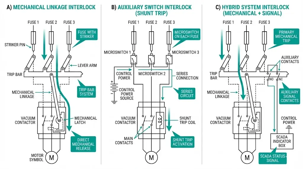
Three interlock architectures dominate F-C switchgear designs. Selection depends on application criticality, maintenance capability, and monitoring requirements.
A lever arm connects all three striker pins to a common trip bar. When any single fuse operates, striker extension rotates the trip bar, which mechanically unlatches the contactor holding mechanism.
Advantages: No auxiliary power required. Response time under 50 ms from striker extension to contactor release. Fail-safe against control circuit failures.
Limitations: Requires precise alignment during assembly. Linkage wear introduces play over time, potentially delaying trip response. Retrofit into existing panels presents mechanical complexity.
Each striker pin actuates a microswitch. The switch contacts wire in series across all three phases. Any single fuse operation opens the series string, de-energizing the contactor holding coil or energizing a shunt trip.
Advantages: Easier installation in modular switchgear designs. Provides remote indication capability for SCADA integration. Lower mechanical complexity per fuse position.
Limitations: Dependent on control voltage availability. Microswitch reliability becomes an additional failure point. Contact bounce or welding possible during high-energy events.
Some manufacturers combine mechanical unlatching with electrical signaling. The mechanical trip provides primary protection while the electrical signal feeds indication, interlocking logic, and event recording.
For motor feeder applications where safety integrity level (SIL) requirements apply, the mechanical interlock typically provides the safety function while electrical signaling handles monitoring and diagnostics.
| Parameter | Mechanical Linkage | Auxiliary Switch | Hybrid |
|---|---|---|---|
| Response Time | < 50 ms | 50–100 ms | < 50 ms (primary) |
| Control Power Required | No | Yes | Partial |
| SCADA Integration | Limited | Full | Full |
| Maintenance Complexity | Moderate (alignment checks) | Low | Moderate |
| Failure Mode Visibility | High (jam visible) | Low (contact hidden) | Mixed |
| Typical Application | Mining, heavy industry | Commercial, OEM panels | Critical process, SIL-rated |
Selection guidance: Mechanical linkage suits applications demanding fail-safe operation without dependence on auxiliary systems. Auxiliary switch interlocks fit installations prioritizing remote monitoring and standardized panel designs. Hybrid configurations address both requirements but add complexity.
Field experience across mining, petrochemical, and manufacturing installations reveals consistent failure patterns. These pitfalls share a common thread: assumptions made during design or commissioning that go unverified until an actual fault exposes the gap.
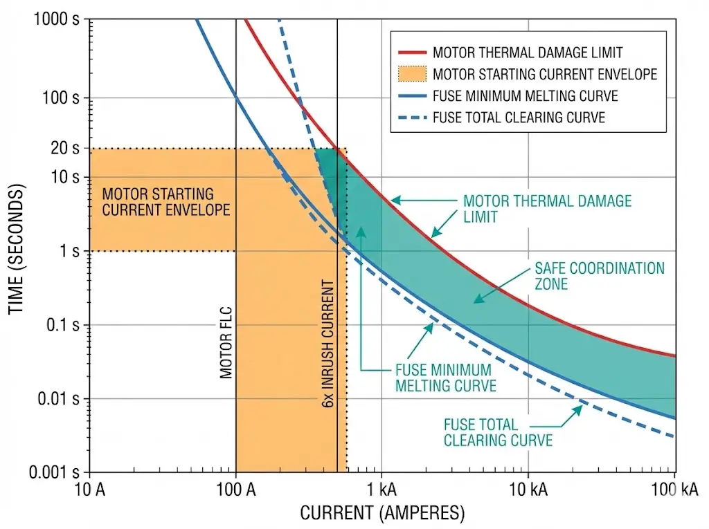
Selecting a fuse rated at 1.5× motor full-load current without examining the starting profile leads to nuisance operations during extended acceleration. High-inertia loads—ball mills, crushers, centrifugal pumps with check valves—may draw 6× FLC for 15–30 seconds.
Field example: A 500 kW mill drive with 20-second acceleration time blew fuses repeatedly until rating increased from 100 A to 125 A. The original selection followed a generic multiplier without examining the motor starting curve against fuse minimum melting time.
Prevention: Overlay motor thermal withstand curve, locked-rotor time limit, and fuse minimum melting curve on a common time-current plot. The fuse curve must remain to the right of the motor inrush envelope at all points.
The fuse’s let-through energy during fault clearing must remain below the contactor’s withstand rating. A contactor rated for 2,000 A²s cannot survive a fuse that allows 5,000 A²s during a 40 kA prospective fault.
Verification method: Obtain the fuse manufacturer’s I²t characteristic (peak let-through vs. prospective fault current) and compare against the contactor’s declared short-circuit withstand from its type test report per IEC 62271-106.
If only one fuse operates—common in phase-to-ground faults on resistance-grounded or ungrounded systems—the motor continues running on two phases. Negative-sequence currents cause rapid, uneven rotor heating.
Mitigation strategies:
Striker pins jam due to corrosion in humid or coastal environments, contamination from dust or oil vapor, manufacturing defects in spring mechanism, or fuse cartridge installed with incorrect orientation.
Field observation: On one offshore platform, 3 of 12 F-C units showed striker pins that failed to extend during routine testing with a manual release tool. Salt fog ingress over 18 months had corroded internal spring guides. The fuses appeared visually intact.
Excessive play from wear or improper assembly allows striker extension without full trip bar rotation. The contactor latch does not release. Single-phasing continues until thermal protection or operator intervention.
Prevention: Include linkage alignment verification in commissioning procedures. Measure trip bar angular displacement against manufacturer specification—typically 12–18 degrees minimum rotation for reliable latch release.
- Never rely on generic coordination curves from handbooks; obtain manufacturer-specific data for both fuse and contactor
- Perform striker actuation test on every F-C unit before energization—not a sample
- Document prospective fault current at installation point; coordination valid only at that level
- Photograph linkage alignment and record measurements for future maintenance comparison
Before energizing any F-C switchgear installation, complete these verification steps:
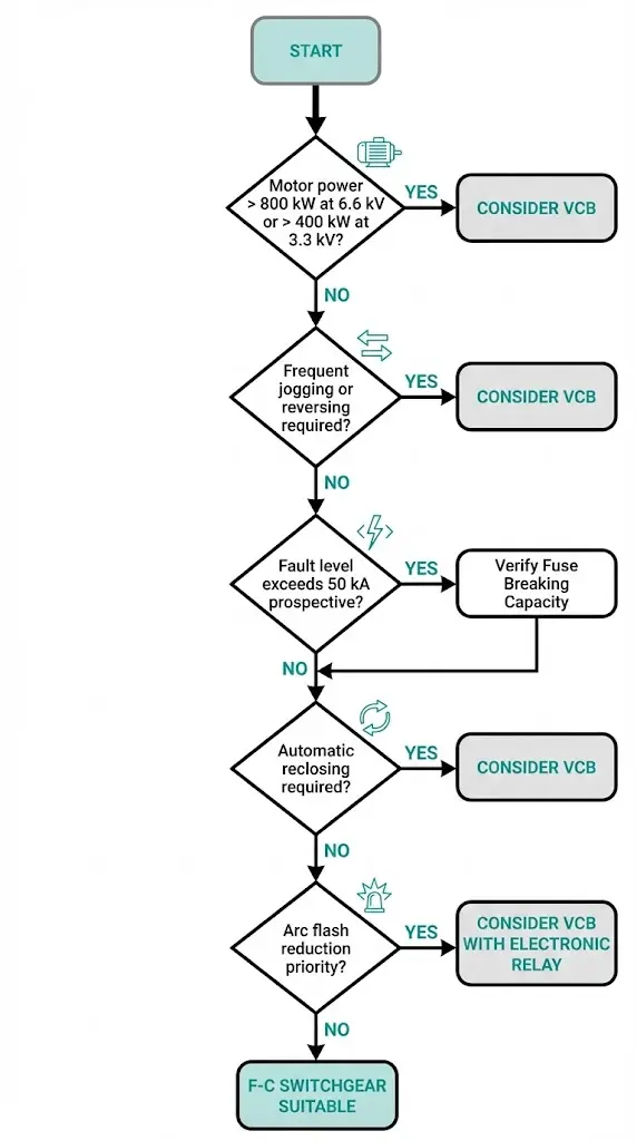
F-C combinations suit motor feeders up to approximately 800 kW at 6.6 kV or 400 kW at 3.3 kV—applications with infrequent switching and predictable load characteristics. The arrangement becomes problematic when:
For these applications, vacuum circuit breakers with electronic protection relays provide greater flexibility. Understanding where F-C switchgear fits—and where it does not—prevents specification errors that surface only during abnormal operating conditions.
XBRELE vacuum contactors are engineered for F-C coordination requirements. Each unit ships with documented I²t withstand values verified through type testing per IEC 62271-106, enabling direct comparison against fuse let-through characteristics.
Mounting provisions accommodate both mechanical linkage and auxiliary switch interlock configurations. For environmental considerations including coastal installations or contaminated atmospheres, enhanced sealing options protect striker interface points.
XBRELE’s engineering team supports coordination studies for motor feeder projects—providing fuse compatibility data, I²t curves, and striker travel specifications. Contact us to request coordination data sheets or schedule a technical consultation for your next motor control center design.
A: Corrosion from humidity or salt fog, contamination from airborne dust or oil vapor, and internal spring fatigue are the primary causes; fuse cartridges installed in incorrect orientation may also prevent full striker extension.
A: Vacuum contactors are rated for load switching, not fault interruption—if the fuse does not clear the fault, the contactor will likely fail catastrophically when attempting to interrupt current beyond its breaking capacity.
A: Annual functional testing is typical for most industrial applications; installations in corrosive environments or with high switching frequency may require testing every 6 months.
A: If fuse let-through I²t exceeds contactor withstand, fault energy may weld contactor contacts or damage the vacuum interrupter, causing failure to isolate the circuit after the fuse clears.
A: The striker may extend fully, but linkage wear, misalignment, or binding can prevent the trip bar from rotating enough to release the contactor latch—mechanical verification during commissioning prevents this failure mode.
A: Mechanical linkage provides fail-safe operation independent of control power availability; hybrid systems combining mechanical trip with electrical monitoring are increasingly specified for SIL-rated motor feeders.
A: F-C suits infrequent switching with predictable loads below 800 kW at 6.6 kV; applications requiring frequent operation, automatic reclosing, or arc flash optimization generally favor vacuum circuit breakers with adjustable electronic protection.