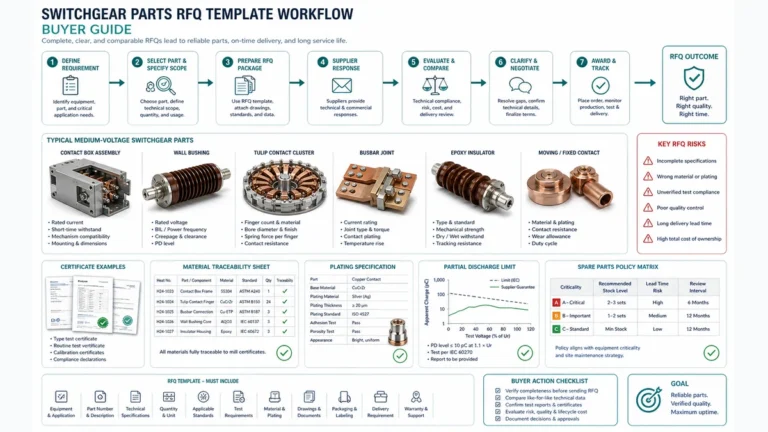
Need Full Specifications?
Download our 2025 Product Catalog for detailed drawings and technical parameters of all switchgear components.
Get CatalogDownload our 2025 Product Catalog for detailed drawings and technical parameters of all switchgear components.
Get CatalogDownload our 2025 Product Catalog for detailed drawings and technical parameters of all switchgear components.
Get Catalog
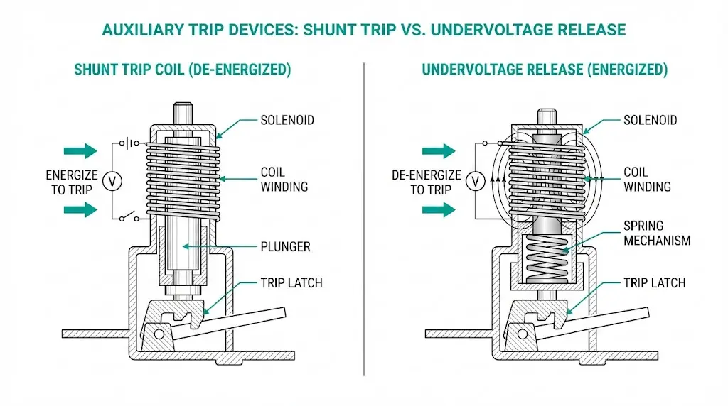
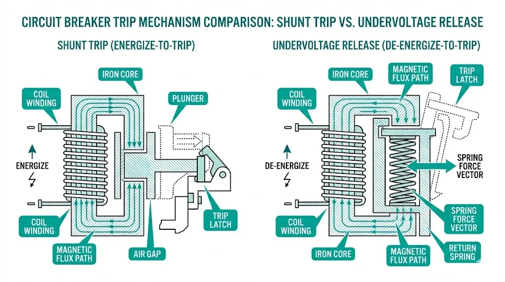
Medium-voltage circuit breakers need auxiliary devices to initiate opening under abnormal conditions. Two mechanisms dominate: the shunt trip coil and the undervoltage release (UVR). Both unlatch the breaker’s stored-energy mechanism—but they operate on fundamentally opposite electrical logic. A shunt trip energizes to trip. An undervoltage release de-energizes to trip.
This inverse relationship determines control circuit topology, failure behavior, safety philosophy, and maintenance strategy. Engineers who treat these devices as interchangeable risk specifying systems that fail dangerously or trip spuriously during normal operation.
The fundamental distinction lies in electrical operating logic and failure behavior.
Shunt Trip Coil: Energize-to-Trip
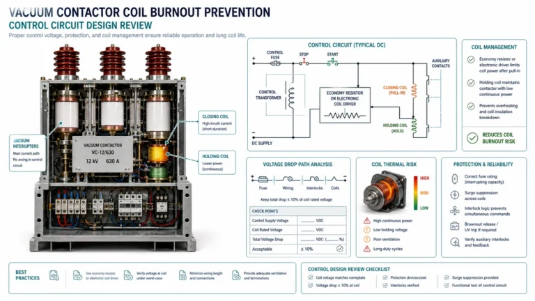
A shunt trip coil remains de-energized during normal breaker operation. When control voltage—typically 110V DC or 220V AC in MV applications—energizes the solenoid, electromagnetic force releases the breaker’s holding latch. The coil requires only momentary energization, typically 50–100 ms, to complete the trip sequence.
Field commissioning across industrial substations documents response times of 20–50 ms from coil energization to contact separation. Shunt trip coils consume 50–200 W during operation, with inrush current reaching 5–10 times steady-state values. Per IEC 62271-100, auxiliary circuits must operate reliably at 85–110% of rated control voltage.
Undervoltage Release: De-Energize-to-Trip
An undervoltage release operates inversely. The coil remains continuously energized during normal operation, holding a spring-loaded mechanical latch in the restrained position. When supply voltage drops below the pickup threshold—typically 35–70% of rated voltage—the spring overcomes weakened electromagnetic hold and trips the breaker.
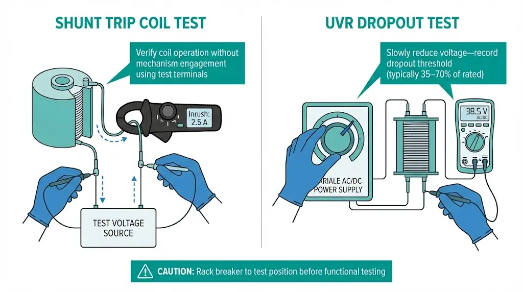
Testing reveals UVR dropout times of 15–40 ms after voltage collapse below threshold. Continuous power consumption ranges from 5–15 W, creating ongoing auxiliary power demand that shunt trips avoid.
Understanding how vacuum circuit breakers function provides essential context, since both devices integrate with the VCB’s spring-charged operating mechanism through the same trip bar interface.
| Parameter | Shunt Trip Coil | Undervoltage Release |
|---|---|---|
| Trigger Logic | Voltage application causes trip | Voltage loss causes trip |
| Normal State | De-energized (no power draw) | Continuously energized |
| Power Consumption | 50–200 W momentary | 5–15 W continuous |
| Response Time | 20–50 ms | 15–40 ms |
| Failure Bias | Fails closed (no trip on coil failure) | Fails open (trips on coil failure) |
| Control Voltage Range | 85–110% of rated | Dropout at 35–70% of rated |
| Coil Duty | Momentary (intermittent) | Continuous |
| Typical Applications | Protection relay outputs, fire system interlocks, E-stops | Safety interlocks, fail-safe isolation, motor feeders |
The failure bias distinction drives most selection decisions. Shunt trips fail toward non-operation—the breaker stays closed when it should open. UVRs fail toward operation—the breaker opens when no actual fault exists. Neither is universally superior; the application determines which failure mode is acceptable.
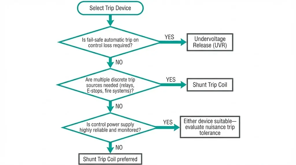
When to Specify Shunt Trip
Shunt trip coils suit applications where:
Typical installations include generator breakers with reverse power protection, fire pump disconnects with sprinkler system interlocks, and transformer feeders with sudden-pressure relay inputs.
When to Specify Undervoltage Release
Undervoltage releases suit applications where:
Typical installations include motor feeders requiring safe shutdown on control failure, tie breakers between independent buses, and isolation breakers in high-hazard areas.
[Expert Insight: Selection Philosophy]
- Petrochemical facilities typically mandate UVR for motor feeders in classified areas—control power loss must guarantee equipment shutdown
- Data centers often prefer shunt trip to prevent cascading outages from control supply transients
- When both devices appear on the same breaker, verify that control logic accounts for their interaction; specifying both without clear functional separation creates maintenance confusion
- Always confirm control voltage source independence from the circuit being protected
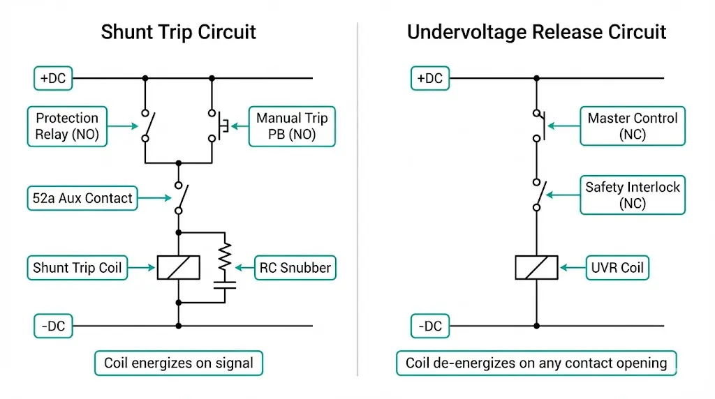
Shunt Trip Circuit
A basic shunt trip circuit consists of:
[+DC] ──┬── [Protection Relay NO] ── [52a Aux] ── [Shunt Coil] ── [-DC]
        │
        └── [Manual Trip PB NO] ─────────────────────┘
The 52a auxiliary contact opens when the breaker trips, interrupting current through the coil. Without this contact, the coil remains energized continuously if the initiating contact latches—causing thermal destruction within seconds.
Undervoltage Release Circuit
A basic UVR circuit consists of:
[+DC] ── [Master Control Switch] ── [Safety Interlock NC] ── [UVR Coil] ── [-DC]
Every normally-closed contact in series represents a trip-initiating condition. Opening any contact drops voltage to the UVR, triggering breaker opening.
Critical Design Notes
DC and AC coils are not interchangeable. DC coils on AC service will chatter due to missing shading rings. AC coils on DC service overheat because they lack impedance to limit current. Always verify coil voltage rating matches supply type exactly.
For authoritative guidance on auxiliary device testing, consult IEEE C37.09 covering circuit breaker test procedures.
Understanding failure modes informs both selection and maintenance strategy.
Shunt Trip Failure Modes
| Failure | Cause | Consequence |
|---|---|---|
| Coil open circuit | Thermal damage, connection failure | Trip command ignored; breaker remains closed |
| Coil short circuit | Insulation breakdown | Control fuse blows; trip may fail |
| Mechanical binding | Corrosion, debris, misalignment | Insufficient force to unlatch mechanism |
| Auxiliary contact weld | Arcing damage, mechanical wear | Coil burnout on next trip command |
Net failure bias: Shunt trips fail toward non-operation. The breaker stays closed when it should open.
Undervoltage Release Failure Modes
| Failure | Cause | Consequence |
|---|---|---|
| Coil open circuit | Thermal damage, connection failure | Immediate trip; breaker cannot remain closed |
| Spring fatigue | Cycling, age, improper adjustment | Intermittent nuisance tripping |
| Mechanical binding | Corrosion, contamination | Trip function disabled; breaker stays closed |
| Control supply failure | Fuse, transformer, wiring fault | Immediate trip (by design) |
Net failure bias: UVR electrical failures typically cause spurious tripping. Mechanical failures can prevent tripping—a less common but more dangerous condition.
Engineers selecting components from a reputable vacuum circuit breaker manufacturer should verify that auxiliary device options meet specific voltage ratings and mechanical interface requirements.
[Expert Insight: Field Failure Observations]
- Shunt trip coil burnout most commonly results from missing or failed 52a auxiliary contacts—always verify auxiliary contact operation during commissioning
- UVR nuisance trips often trace to control transformer sizing; continuous UVR holding current can cause voltage sag below dropout threshold during motor starting on the same control bus
- In high-humidity environments, UVR spring mechanisms show corrosion-related binding after 8–12 years; coastal installations require more frequent inspection
- Coil resistance measurement during routine maintenance provides early warning of winding degradation before complete failure
Temperature Effects
Coil resistance increases with temperature, reducing holding force (UVR) or trip force (shunt trip). At elevated ambient temperatures, UVR dropout voltage rises—potentially causing nuisance trips during summer peaks. Conversely, cold environments thicken lubricants on mechanical linkages, increasing friction and potentially binding trip mechanisms.
Maintenance Intervals
For shunt trip coils:
For undervoltage releases:
Maintenance procedures should integrate with broader switchgear component programs to ensure systematic coverage across all auxiliary devices.
XBRELE manufactures vacuum circuit breakers and switchgear components with full auxiliary device compatibility. Our engineering team provides:
Understanding vacuum interrupter technology helps contextualize how auxiliary trip devices integrate with primary interrupting components in modern MV switchgear.
Contact XBRELE today for specification assistance or to request a quotation for vacuum circuit breakers with properly matched auxiliary trip devices.
Q: Can I install both a shunt trip and undervoltage release on the same circuit breaker?
A: Most MV breakers accommodate both devices mechanically, but the control logic becomes complex and requires careful coordination to prevent conflicting trip signals or maintenance confusion during testing.
Q: What happens if I use a DC-rated coil on an AC control supply?
A: The coil will chatter continuously because DC coils lack shading rings that AC coils use to maintain magnetic force through zero-crossing points, leading to rapid mechanical wear and potential mechanism damage.
Q: How do I test a shunt trip coil without causing an actual breaker trip during operation?
A: Many manufacturers provide isolated test terminals that allow coil energization verification through current measurement without engaging the mechanical trip latch—consult your specific breaker documentation for test port availability.
Q: Why does my UVR cause nuisance trips during motor starting on adjacent feeders?
A: The control transformer likely experiences voltage sag below the UVR dropout threshold during motor inrush; solutions include a dedicated control supply, larger transformer, or adding a 0.5–2 second time delay relay.
Q: What is the typical service life of auxiliary trip devices in MV switchgear?
A: Shunt trip coils typically achieve 5,000–10,000 operations or 15–20 years under normal service conditions, while UVR coils may require replacement sooner due to continuous energization and associated thermal stress.
Q: Which device is better for emergency stop applications?
A: Shunt trip is generally preferred for E-stop because it requires active signal application to trip; UVR would cause spurious trips if E-stop wiring is damaged, disconnected, or loses power for any reason.
Q: Should UVR control power come from the same bus the breaker protects?
A: Generally avoid this topology—if the UVR trips the breaker feeding its own control transformer, a lockout condition results where the breaker cannot reclose without external power restoration.