Need Full Specifications?
Download our 2025 Product Catalog for detailed drawings and technical parameters of all switchgear components.
Get CatalogDownload our 2025 Product Catalog for detailed drawings and technical parameters of all switchgear components.
Get CatalogDownload our 2025 Product Catalog for detailed drawings and technical parameters of all switchgear components.
Get Catalog
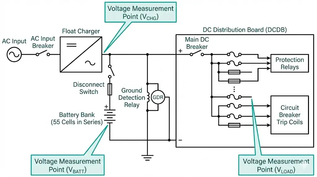
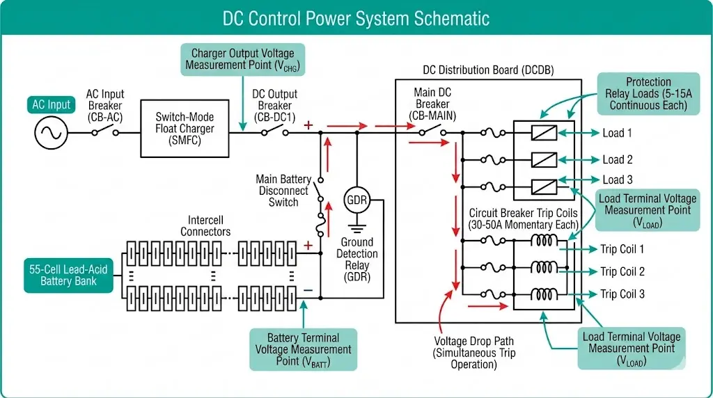
A substation DC control power system is an independent electrical supply—typically 110V or 125V DC from a battery bank and charger—that powers protection relays, circuit breaker trip coils, and control circuits regardless of AC system conditions. When this foundation fails, circuit breakers cannot trip, relays cannot operate, and faults burn unchecked.
Field experience across 50+ industrial substations reveals a troubling pattern: 15-20% of protection relay “failures” actually trace back to degraded DC system performance. The relay worked fine. The battery didn’t.
Protection relays require stable DC voltage within ±10% of nominal rating. A 125V DC system sagging to 95V during a fault—when multiple trip coils demand current simultaneously—may fail to operate breakers within the required 3-5 cycle clearing time. The protection scheme looked perfect on paper. The undervoltage killed it in practice.
Station batteries in utility and industrial applications typically consist of lead-acid cells (flooded or VRLA type) rated for 8-hour discharge capacity. Sizing calculations per require batteries to supply worst-case loads including:
Continuous loads: relay burden, indicating lights, SCADA RTUs (typically 5–15A total)
Testing in mining applications with frequent load switching revealed that batteries degraded below 80% capacity failed to support simultaneous tripping of multiple breakers during bus faults. Coordinated protection collapsed precisely when it mattered most.
The charger must maintain float voltage between 2.17–2.25V per cell (130–135V for 60-cell strings) while providing current for both continuous loads and battery recharge. Charger failures often manifest gradually through voltage regulation drift—making periodic verification essential.
Two battery technologies dominate substation applications:
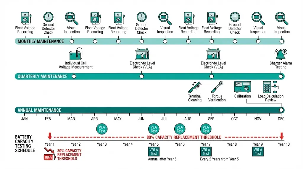
Vented Lead-Acid (VLA): Flooded cells with removable caps requiring periodic water addition. They produce hydrogen during charging and need ventilated rooms. Lifespan reaches 15-20 years with proper maintenance—but “proper” means quarterly electrolyte checks and annual equalization charges.
Valve-Regulated Lead-Acid (VRLA): Sealed construction using absorbed glass mat or gel electrolyte. Lower maintenance requirements, but less tolerant of overcharging and high ambient temperatures. Expect 10-12 years under favorable conditions. At 35°C continuous room temperature, that drops to 5-6 years.
Cell configuration depends on target voltage. A 110V DC system uses 55 cells at 2.0V nominal. A 125V DC system uses 60 cells. Series connections mean one weak cell affects the entire string.
The charger operates in three modes:
Modern switch-mode chargers provide precise regulation and digital monitoring. Older ferroresonant designs still operate in many facilities—functional but less precise.
[Expert Insight: Battery Room Realities]
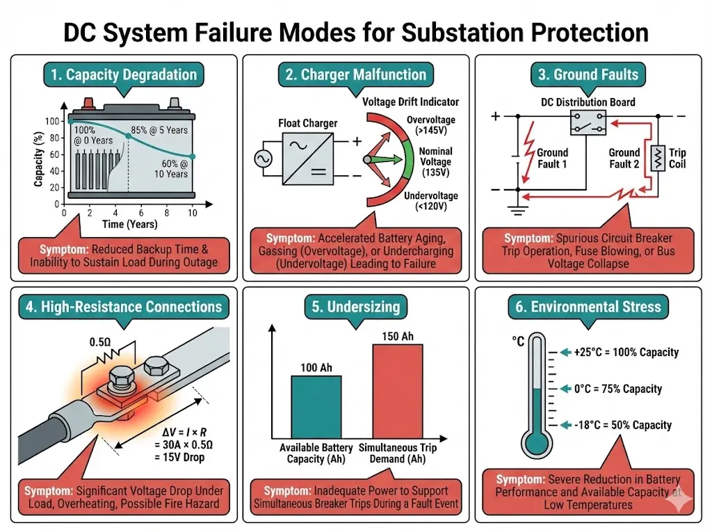
The charger masks this problem beautifully. Voltage looks normal during float operation. Current draw appears stable. Then AC power fails, and a 10-year-old VRLA bank delivers 60% of rated capacity. Backup time collapses from 8 hours to under 3.
Symptoms emerge only under load: rapid voltage sag when the charger goes offline, shortened backup duration, and cell voltage imbalance under discharge stress.
Complete shutdown is obvious. Voltage drift is not. An overvoltage condition (above 2.30V/cell float) accelerates grid corrosion and dries electrolyte. Undervoltage leaves batteries partially discharged, reducing backup capacity and accelerating sulfation.
Critical alarm thresholds for a 110V DC system:
| Alarm Condition | Threshold | Consequence |
|---|---|---|
| DC High Voltage | >126V | Equipment damage, accelerated battery aging |
| DC Low Voltage | <105V | Battery discharging, charger possible failure |
| Charger AC Fail | Input lost | Battery carrying full load |
| Ground Fault | >0.5mA to earth | Insulation degradation detected |
Most substation DC systems operate ungrounded. This design tolerates a single ground fault—no return path means no current flow. The system continues operating while you locate the problem.
A second ground fault changes everything. If the first fault sits on the positive bus and the second contacts a trip coil’s negative terminal, current flows through earth. The trip coil may operate spuriously. Or worse: faults that bypass the trip coil entirely prevent operation during actual faults.
A loose battery terminal shows negligible resistance at 2A float current. That same connection at 30A trip coil current drops voltage below the coil’s operating threshold. The 0.5Ω resistance that seemed acceptable creates a 15V drop under load.
Thermal cycling from daily temperature swings loosens bolted connections progressively. Battery posts and intercell connectors are the usual culprits.
Load profiles divide into continuous (relays, indicators: 5-15A), momentary (trip coils: 30-50A for 100-200ms), and emergency (lighting, ventilation during outage). Undersized banks handle normal operation but fail when a bus fault demands simultaneous multiple breaker trips.
Capacity decreases with temperature:
| Temperature | Approximate Capacity |
|---|---|
| 25°C | 100% (reference) |
| 15°C | 90% |
| 0°C | 75% |
| -18°C | 50% |
Heat accelerates aging—battery life halves for every 8-10°C above 25°C sustained. Outdoor substations in hot climates see VRLA replacement cycles of 6-7 years instead of 12.
Ground fault location requires systematic isolation:
Step 1: Confirm fault indication on the ground detection relay or insulation monitoring device. Note whether the fault is on the positive or negative bus.
Step 2: Open branch circuit breakers sequentially, starting with the largest or most suspect circuits.
Step 3: Monitor the ground detector after each breaker opens. When the fault indication clears, you’ve isolated the faulted branch.
Step 4: Within the faulted branch, segment and test further using the same open-and-monitor approach.
Step 5: Inspect common fault locations:
Detection equipment includes resistance-balanced bridge circuits, voltage dividers with center-tap reference, and active insulation monitoring devices providing quantitative readings in kΩ.
[Expert Insight: Ground Fault Hunting]
The consequences cascade:
Protection relays lose power. Fault detection stops. The overcurrent element that should pick up in 20ms sees nothing because its power supply is dead.
Trip coils remain unpowered. Even if a backup relay operates via CT-powered scheme, the vacuum circuit breaker cannot trip without DC to its coil. The mechanism sits latched while fault current flows.
SCADA communication fails. Operators cannot see the developing problem. Alarms that should have triggered minutes earlier never reached the control room.
Automatic reclosing disables. The restoration sequence that would have re-energized the line after a transient fault cannot execute.
The fault burns until upstream protection operates—if upstream protection has healthy DC supply. Otherwise, equipment destruction eventually limits the fault current. Transformer windings fail. Cables explode. Arc flash incidents escalate.
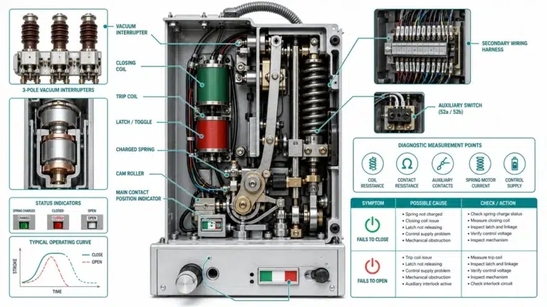
Trip coil voltage tolerance matters here. Most coils specify 80-110% of nominal voltage for reliable operation. A 110V DC coil needs at least 88V to generate sufficient force to unlatch the mechanism. Below that threshold, partial operation or complete failure occurs.
Understanding vacuum circuit breaker trip requirements helps specify DC systems correctly: vacuum circuit breaker working principle
Monthly Tasks:
Quarterly Tasks:
Annually:
Capacity Testing:
Matching DC voltage to breaker specifications prevents operational failures. Verify trip coil voltage rating, minimum operating voltage, and maximum continuous voltage before finalizing DC system design. The vacuum interrupter depends on reliable mechanism operation: vacuum interrupter basics
Redundancy options for critical installations include:
Continuous battery monitoring systems measure individual cell voltage, intercell connection resistance, and ambient temperature. They trend data and alarm on deviations before failures occur—justifying their cost through early warning and reduced manual inspection burden.
Include DC control voltage requirements in procurement specifications. The RFQ checklist at VCB RFQ checklist covers control circuit parameters alongside primary ratings. For complete vacuum circuit breaker solutions with properly matched control systems, contact XBRELE’s engineering team: vacuum circuit breaker manufacturer overview
External Reference: IEC 62271-106 — IEC 62271-106 standard for AC contactors
Q: What DC voltage level is most common for medium-voltage substation protection?
A: 110V DC predominates in IEC-aligned regions including China and Europe, while 125V DC is standard in North American utility substations following IEEE/ANSI practices. Selection depends on regional standards and installed equipment compatibility.
Q: How long should a properly sized battery bank provide backup power?
A: Design practice typically specifies 4-8 hours of autonomy, providing sufficient time for operator response or utility crew restoration. Critical facilities may specify longer duration based on restoration time analysis.
Q: Why do substations use ungrounded DC systems instead of grounded?
A: Ungrounded systems continue operating with a single ground fault, allowing time to locate and repair the problem before a second fault causes protection failure. This resilience comes at the cost of requiring ground detection equipment and systematic fault location procedures.
Q: How can I tell if battery capacity has degraded without a discharge test?
A: Individual cell voltage spread during float charging indicates relative cell health—cells more than 0.05V from string average warrant investigation. However, only a controlled discharge test reveals actual available capacity under load conditions.
Q: What causes circuit breaker trip failures that appear random?
A: High-resistance connections in the DC supply path create voltage drops that appear only during high-current trip coil operation. Float voltage measurements show normal readings, but the connection fails under the 30-50A momentary load of trip coil operation.
Q: Can battery monitoring systems replace periodic discharge testing?
A: Monitoring systems provide continuous trending and early warning of cell deterioration but measure indirect indicators rather than actual deliverable capacity. Industry practice uses monitoring to optimize test scheduling rather than eliminate testing entirely.
Q: What is the typical replacement interval for VRLA batteries in substations?
A: VRLA batteries in climate-controlled environments typically require replacement at 10-12 years. Elevated ambient temperatures, frequent deep discharges, or capacity test results below 80% of rating trigger earlier replacement regardless of age.