Need Full Specifications?
Download our 2025 Product Catalog for detailed drawings and technical parameters of all switchgear components.
Get CatalogDownload our 2025 Product Catalog for detailed drawings and technical parameters of all switchgear components.
Get CatalogDownload our 2025 Product Catalog for detailed drawings and technical parameters of all switchgear components.
Get Catalog
Medium voltage cable accessories—terminations and joints—represent the highest-risk components in any 6 kV to 36 kV distribution system. Field data consistently shows that approximately 70% of MV cable system failures originate at accessories rather than cable insulation itself. This guide evaluates leading manufacturers and provides a comprehensive procurement checklist to minimize failure risk in your installations.
Cable accessories fail more often than cables themselves. This reality surprises many procurement engineers, yet field evidence supports it across voltage classes and geographic regions.
MV cable systems comprise three elements: the cable, terminations at each end, and joints along the route. Cables manufactured under controlled factory conditions with continuous quality monitoring rarely fail during service life. Terminations and joints—assembled on-site by installation crews facing weather, confined spaces, and schedule pressure—carry fundamentally different risk profiles.
The cost-risk asymmetry demands attention:
A single 11 kV joint failure in an industrial facility can cascade into production losses exceeding the entire cable system cost within hours. Underground failures in urban networks require street excavation and traffic disruption—multiplying direct repair costs tenfold.
This failure distribution places disproportionate weight on accessory selection. Procurement decisions that optimize cable specification while treating accessories as commodity purchases invert rational risk management entirely.
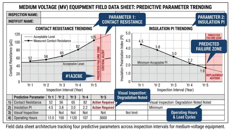
When cable insulation is cut and exposed during accessory installation, electric field intensity at the insulation edge can exceed 40 kV/mm—far surpassing the material’s dielectric strength of approximately 20–25 kV/mm. Accessories without proper stress control fail within 6–18 months due to partial discharge initiation at these high-stress zones.
Core Function and Physics
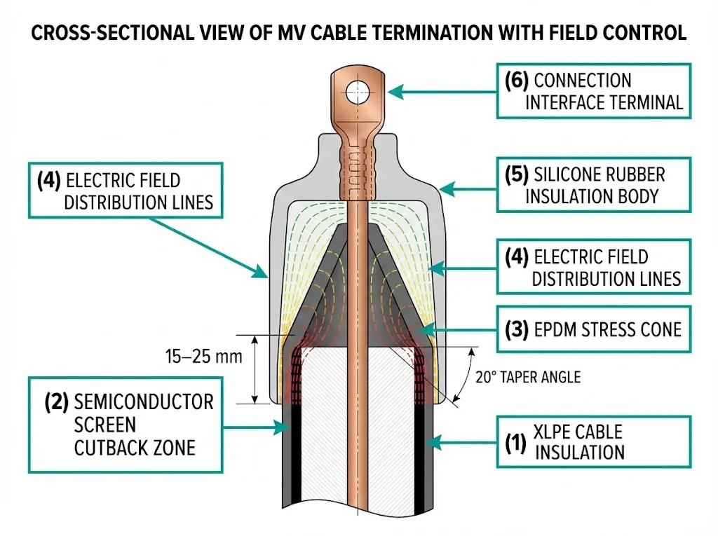
MV cable terminations serve two purposes: providing electrical stress control at the cable end and creating a reliable connection interface with switchgear interface components or transformers. When cable insulation is stripped, concentrated electric fields at the semiconductor cutback point can reach stress levels exceeding 10 kV/mm. Termination accessories employ geometric or refractive stress control methods to redistribute this field gradient to acceptable levels below 4 kV/mm.
Cable joints restore electrical integrity when connecting two cable sections. The joint body must match or exceed the cable’s insulation performance, maintaining dielectric strength across temperature cycles from -40°C to +90°C during normal operation.
Stress Control Mechanisms
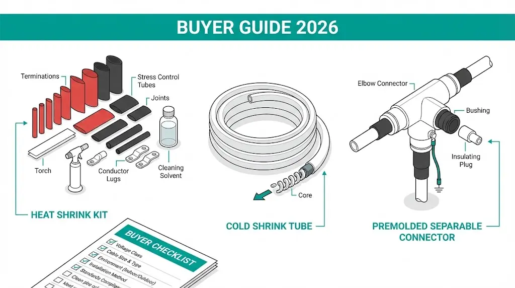
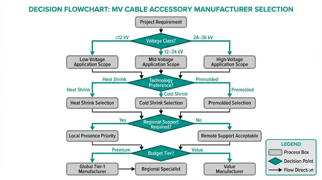
Three primary technologies dominate the market:
| Technology | Mechanism | Installation Requirement | Best Application |
|---|---|---|---|
| Heat Shrink | Polymer memory activation via torch (90–120°C) | Skilled installer, open workspace | Budget projects, outdoor environments |
| Cold Shrink | Pre-stretched EPDM tube release | No heat, faster installation | Confined spaces, safety-critical sites |
| Premolded/Separable | Factory-molded interface components | Dimensional precision required | Switchgear connections, frequent access |
Geometric stress cones—typically EPDM or silicone rubber—physically reshape electric fields by extending the insulation surface with cone angles ranging from 15° to 25°. Refractive stress control uses high-permittivity materials (εr = 20–30) that redistribute fields through capacitive coupling. Resistive stress grading applies non-linear conductive layers that automatically balance field distribution under varying conditions.
According to IEC 60502-4, MV cable accessories must demonstrate partial discharge levels below 10 pC at 1.73 × U₀ during type testing—a critical benchmark for buyer verification.
[Expert Insight: Field Installation Observations]
- Cold shrink accessories reduce installation time by 40–60% compared to heat shrink alternatives in confined substation environments
- Interface pressure between accessory and cable insulation must maintain 0.1–0.3 MPa contact stress throughout the -40°C to +90°C operating range
- Silicone grease or specialized compounds filling microscopic air gaps reduce partial discharge inception voltage by 15–20% compared to dry installations
- Incorrect cable outer diameter measurement accounts for approximately 25% of premature accessory failures
Selecting an MV cable accessory manufacturer requires evaluating technical capability, certification depth, and regional support infrastructure. The following assessment draws from procurement evaluations across industrial, utility, and renewable energy projects.
Global Tier-1 Manufacturers
| Manufacturer | Origin | Voltage Coverage | Core Technology | Certification Base |
|---|---|---|---|---|
| 3M Electrical | USA | ≤42 kV | Cold shrink pioneer | IEEE 48, IEC 60502-4 |
| TE Connectivity (Raychem) | Switzerland | ≤42 kV | Heat shrink originator | IEEE 48, IEC 60502-4 |
| Prysmian Group | Italy | ≤170 kV | Integrated cable systems | IEC, IEEE, regional |
| Nexans | France | ≤420 kV | Project solutions focus | IEC, IEEE |
| Brugg Cables | Switzerland | ≤170 kV | Premolded specialty | IEC 60502-4 |
| Pfisterer | Germany | ≤72 kV | Separable connectors | IEC, IEEE |
Regional Manufacturers with Verified Type Testing
Asia-Pacific markets increasingly source from LS Cable (Korea), Taihan Electric (Korea), and Zhongtian Technology (China)—all achieving competitive pricing with improving quality certifications. Middle East projects frequently specify Riyadh Cables (KSA) or Ducab (UAE) for regional compliance expertise and local support networks. Indian manufacturers including Raychem RPG and Yamuna Cable Accessories provide value positioning with IEEE 48 compliance.
Selection Note: Verify product-specific type test reports, not company-level certifications. A manufacturer may hold IEC 60502-4 certification for 12 kV products while lacking equivalent validation for 36 kV accessories.
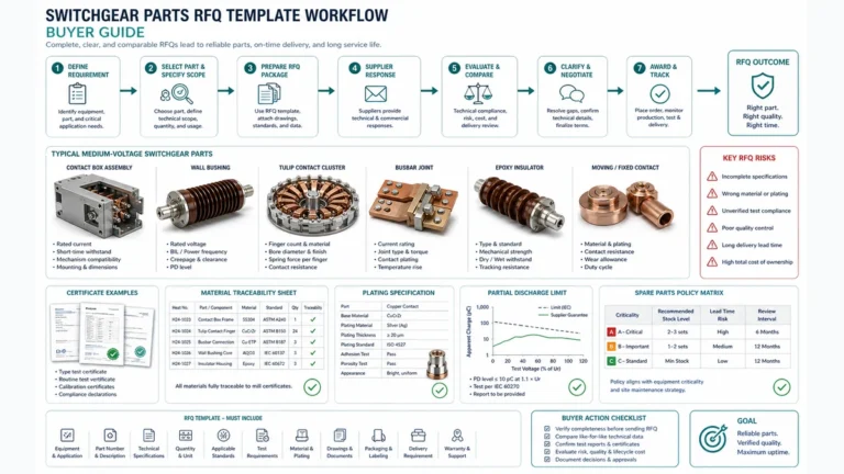
Technical due diligence separates reliable installations from premature failures. The following parameters require verification against actual project requirements—not assumptions based on cable specifications alone.
Voltage and Insulation Parameters
Cable Compatibility Requirements
Conductor size range verification extends beyond nominal values. Confirm mm² coverage with margin for potential future cable upsizing. Insulation type compatibility—XLPE, EPR, or PILC—must appear explicitly on accessory datasheets. Semiconductor screen matching (strippable versus non-strippable) directly affects interface integrity; wrong combinations cause breakdown at the cable-accessory boundary.
Environmental Ratings
Operating temperature ranges typically span -40°C to +50°C ambient for standard accessories. Outdoor terminations require UV-stabilized silicone or EPDM with demonstrated hydrophobicity retention. Pollution class determination per IEC 60815 (light, medium, heavy, very heavy) dictates minimum creepage distances—similar creepage requirements apply to wall bushings in switchgear applications. Altitude ratings apply to 1,000 m; installations above require derating of approximately 1% per 100 m or enhanced insulation specifications.
Understanding certification frameworks enables buyers to validate manufacturer claims and compare products across different testing regimes.
Standard Scope Comparison
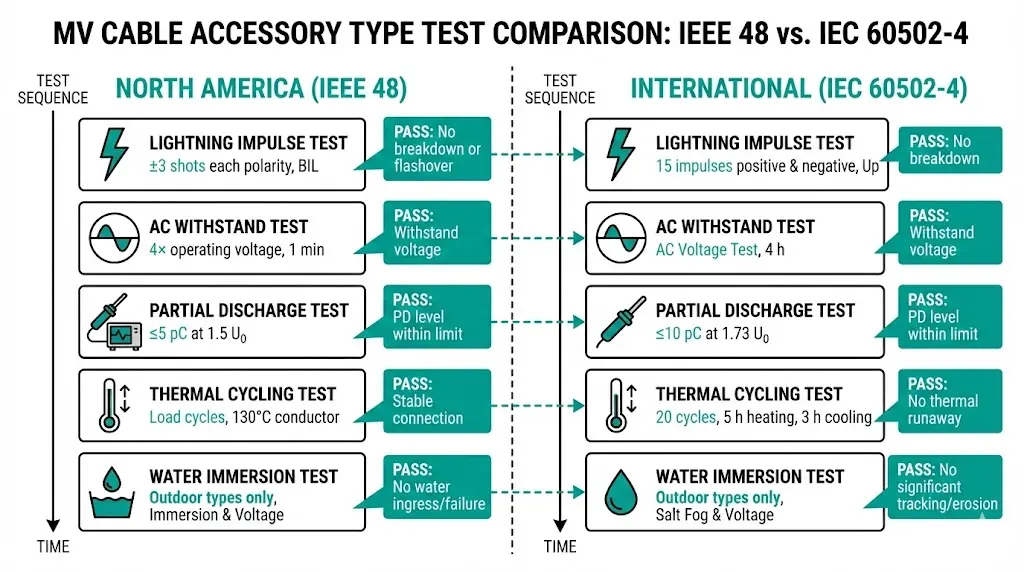
IEEE 48 governs North American requirements for cable terminations rated 2.5 kV–500 kV, prescribing specific impulse, AC withstand, and partial discharge test sequences. IEC 60502-4 provides the international framework for accessories serving 6 kV–36 kV extruded insulation cables, with modular test programs adaptable to specific product configurations.
Key Type Test Requirements
| Test Category | IEEE 48 Requirement | IEC 60502-4 Requirement |
|---|---|---|
| Lightning Impulse | Full BIL, ±3 shots each polarity | Full BIL, 15 impulses |
| AC Withstand | 4× rated duration | Per specific test sequence |
| Partial Discharge | ≤5 pC at specified voltage | ≤10 pC typical threshold |
| Thermal Cycling | Load cycle sequence | 20 cycles at 1.2× rated current |
| Water Immersion | Required for outdoor types | Required for outdoor joints/terminations |
Verification Guidance
Request full type test reports rather than summary certificates. Confirm testing laboratory accreditation through ILAC, A2LA, or equivalent bodies. Most critically, verify that the specific product tested matches your procurement specification exactly—accessory families often include variants with different voltage ratings or cable compatibility ranges.
[Expert Insight: Certification Verification]
- Third-party laboratory reports carry more weight than manufacturer self-declarations
- KEMA (Netherlands), CESI (Italy), and CEPRI (China) represent widely recognized MV accessory testing facilities
- Dual IEEE 48 and IEC 60502-4 certification indicates broader market acceptance and design maturity
- Request thermal cycling test data specifically if your application involves frequent load variations
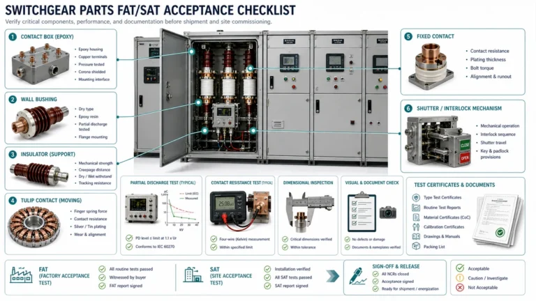
This checklist consolidates critical verification points into an actionable procurement framework. Each item addresses failure modes observed in field installations.
Apply similar verification rigor to switchgear components when specifying complete substation solutions.
Product specifications establish baseline capability. Installation workmanship determines actual field performance. In our assessments across mining, petrochemical, and utility installations, installation defects cause more accessory failures than product deficiencies.
Training Program Value
Tier-1 manufacturers offer certified installer programs—3M’s Quality Installation Inspection Program (QIIP) and Raychem certification represent industry benchmarks. Training scope covers cable preparation techniques, tool usage protocols, and quality inspection checkpoints. Specifying installer certification as a bid requirement provides measurable quality assurance without subjective evaluation.
Field Support Realities
First-time product installations warrant manufacturer supervision, particularly for complex applications such as 33 kV transition joints or submarine cable terminations. Technical hotline availability (24/7 for critical projects) enables real-time problem resolution during time-sensitive installations. Understanding warranty void conditions—improper cable preparation, incorrect tool use, environmental exposure during installation—prevents coverage disputes.
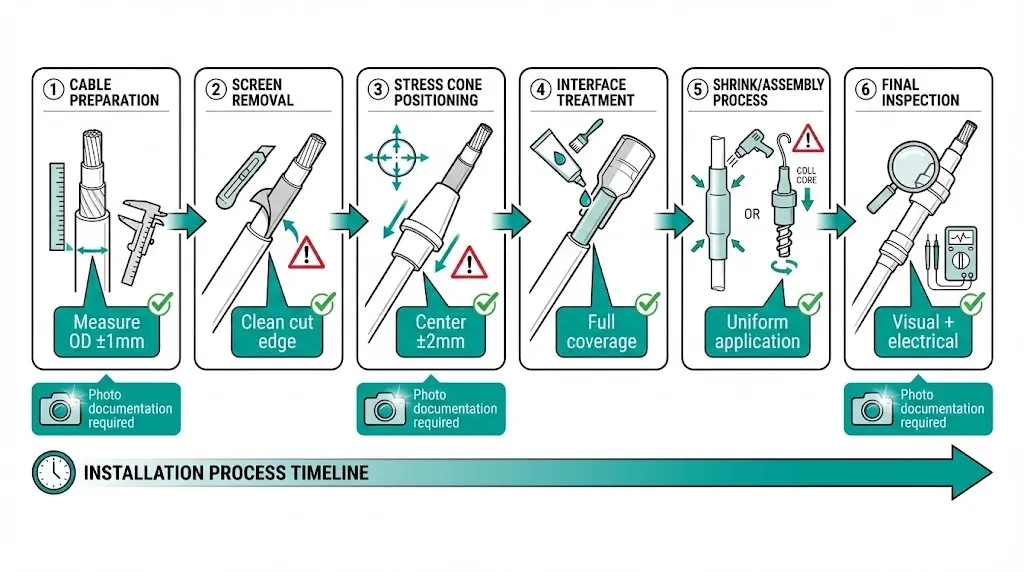
Documentation Requirements
Photograph key installation stages: cable preparation measurements, stress cone positioning, final assembly. This documentation protects warranty claims and enables failure analysis if problems develop. Quality-focused contractors maintain installation logs as standard practice.
Choose XBRELE when cable terminations, joints, separable connectors, and switchgear interfaces must be checked together. This is especially important for retrofit panels, compact RMU layouts, and projects where installation quality affects partial-discharge risk.
| Buyer requirement | XBRELE support focus | Information needed for quotation |
|---|---|---|
| Termination or joint selection | Match voltage class, insulation type, conductor size, screen type, and indoor/outdoor installation. | Cable data sheet, conductor size, insulation material, voltage class, and installation environment. |
| Switchgear interface | Check bushing type, separable connector angle, panel clearance, and earthing arrangement. | Panel drawing, bushing standard, cable entry direction, and available installation space. |
| Quality and acceptance control | Align accessory selection with PD, withstand, and installation inspection requirements. | Required standards, test documents, installation method, and acceptance checklist. |
MV cable accessories interface directly with switchgear systems at termination compartments, bushing connections, and separable connector interfaces. Reliable cable system performance depends on proper coordination between accessory specifications and switchgear design parameters.
XBRELE supplies MV switchgear components engineered for dependable cable interface performance:
Explore XBRELE’s switchgear component solutions for your next distribution project.
What causes most MV cable accessory failures?
Installation workmanship accounts for the majority of accessory failures, particularly improper cable preparation, inadequate stress cone positioning, and contamination introduced during field assembly. Product defects represent a smaller proportion when accessories from reputable manufacturers are specified.
How do I verify if a manufacturer’s type test certification is legitimate?
Request the complete type test report rather than summary certificates, confirm the testing laboratory holds ILAC or equivalent accreditation, and verify the tested product specification matches your procurement requirements exactly—including voltage class, cable compatibility range, and environmental ratings.
Can I mix cable accessories from different manufacturers on the same project?
Yes, provided each accessory is independently type-tested and compatible with the specific cable type being terminated or jointed. However, using a single manufacturer simplifies warranty administration and technical support coordination during installation.
What is the typical service life of properly installed MV cable accessories?
Quality MV cable terminations and joints from established manufacturers typically achieve 25–40 years of service under normal operating conditions, matching or exceeding cable insulation life. Thermal cycling frequency, environmental exposure severity, and installation quality significantly influence actual longevity.
Is cold shrink technology better than heat shrink for MV applications?
Cold shrink eliminates torch-related fire risks and typically reduces installation time by 40–60%, making it preferable for confined spaces and safety-critical environments. Heat shrink provides superior mechanical protection for outdoor and abrasion-prone applications at lower material cost. Selection depends on project-specific requirements rather than absolute superiority.
What altitude requires special consideration for MV cable accessories?
Standard MV cable accessory ratings apply up to 1,000 meters altitude. Above this elevation, reduced air density decreases external insulation strength, requiring enhanced creepage distances or BIL derating of approximately 1% per 100 meters per manufacturer guidelines.
How should I store MV cable accessories before installation?
Store accessories in original packaging at temperatures between 0°C and 35°C, away from direct sunlight and moisture. Cold shrink products have shelf-life limitations (typically 3–5 years) due to rubber relaxation—verify expiration dates before installation. Heat shrink and premolded accessories generally tolerate longer storage periods.