Need Full Specifications?
Download our 2025 Product Catalog for detailed drawings and technical parameters of all switchgear components.
Get CatalogDownload our 2025 Product Catalog for detailed drawings and technical parameters of all switchgear components.
Get CatalogDownload our 2025 Product Catalog for detailed drawings and technical parameters of all switchgear components.
Get Catalog
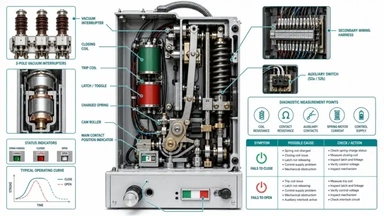
A drawout vacuum circuit breaker stuck between positions creates overlapping hazards—exposed live contacts, ambiguous interlock states, and arc flash potential measured in calories per square centimeter rather than abstract risk categories. Field engineers who rack these breakers weekly understand that the mechanical complexity enabling convenient maintenance also introduces failure modes absent from fixed-mount designs.
Drawout VCB racking describes the controlled movement of a removable breaker truck between defined positions within a switchgear compartment. The breaker connects to the power system through separable contacts—spring-loaded finger clusters on the truck engage stationary bus-side contacts when moved forward, then separate completely when withdrawn. Three critical subsystems govern this operation: the rail guidance system, the automatic shutter assembly, and the position detent mechanism.
This guide addresses practical safety concerns encountered during racking operations: how shutters protect against contact exposure, what causes alignment failures, why half-position represents the highest-risk state, and systematic field checks that prevent incidents before they occur.
The racking mechanism operates through a precise sequence synchronized with multiple safety devices. When the VCB truck moves along hardened steel guide rails (typically rated for 500+ insertion cycles before requiring lubrication), cam-operated shutters respond to truck position. Contact alignment tolerances must remain within ±1.5 mm to ensure proper primary disconnect engagement—a specification verified through commissioning inspections at industrial substations.
According to IEC 62271-200 (metal-enclosed switchgear), automatic shutters must provide isolation barriers rated to withstand the full system voltage—typically 12 kV or 24 kV for medium-voltage applications. The shutter actuation force generally requires 80–150 N depending on manufacturer design.
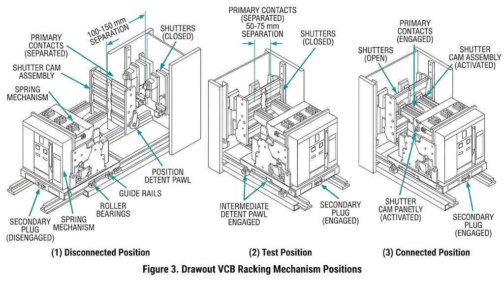
Three defined racking positions exist in standard drawout switchgear:
Disconnected Position: VCB fully withdrawn, all primary contacts separated by full design clearance (typically 100–150 mm), shutters closed. Safe for breaker inspection or complete removal.
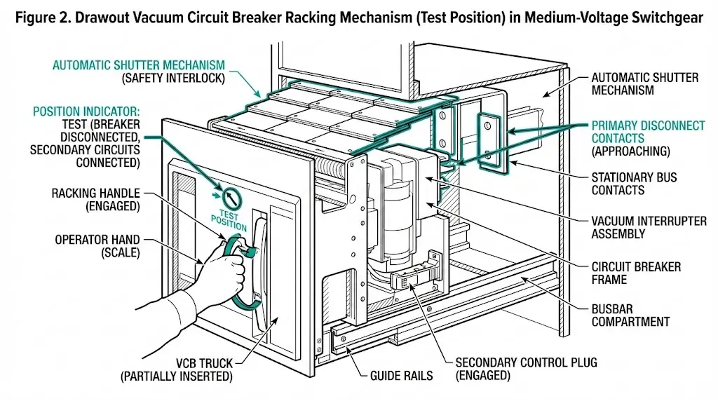
Test Position: VCB partially inserted to a mechanical detent, primary contacts open, control circuits connected through the secondary plug. Permits functional verification of close/trip coils without energizing main bus connections. Shutters remain closed.
Connected Position: VCB fully engaged, primary disconnect contacts mated under spring pressure sufficient to carry rated current (630 A to 4,000 A typical), ready for service.
Position detents typically engage at 25 mm intervals during racking travel, providing tactile feedback to operators. Spring-loaded pawls must overcome 40–60 N resistance to advance between positions, ensuring deliberate movement rather than accidental displacement.
[Expert Insight: Racking Mechanism Wear Indicators]
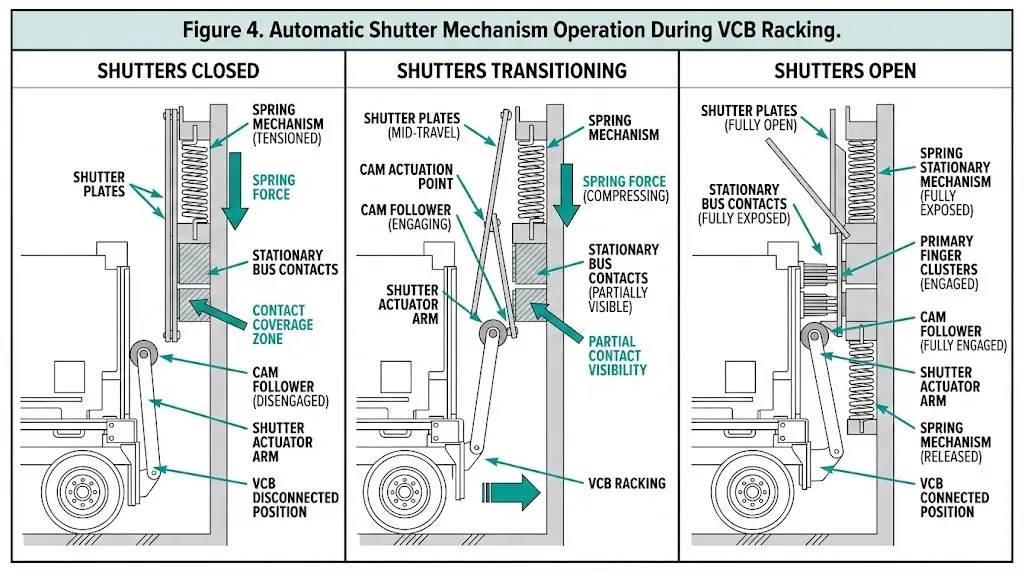
Automatic shutters serve as the primary barrier between personnel and energized bus-side contacts when the breaker is withdrawn. These spring-loaded metallic or composite barriers physically cover primary disconnect contacts, preventing accidental contact with conductors rated at 12 kV or higher. Field assessments across industrial switchgear installations reveal that shutter system failures account for a significant percentage of racking-related safety incidents.
The shutter mechanism operates through direct mechanical linkage with the breaker truck position. As the VCB moves from the connected position toward withdrawal, cam followers engage shutter drive mechanisms that rotate or translate shutter plates across the stationary primary contacts. This movement must complete within the first 50 mm of carriage travel to ensure contact coverage before the primary disconnects separate.
According to IEC 62271-200, shutter systems must provide a minimum dielectric withstand capability of 28 kV at system voltages of 12 kV. The standard requires shutters to achieve complete closure before primary contacts separate by more than 3 mm gap distance. This timing relationship prevents arc flash hazards from residual voltage or capacitive discharge.
Shutter Construction and Materials
Shutter plates typically employ glass-reinforced polyester (GRP) or phenolic composite materials with embedded metallic grading shields. These materials maintain structural integrity across temperature ranges of -25°C to +70°C while providing adequate creepage distances of ≥125 mm phase-to-phase. Spring mechanisms driving shutter closure develop 80–120 N force to overcome contamination buildup and ensure positive engagement after years of service.
The interlock coordination between shutter position and breaker racking represents critical safety engineering. Modern switchgear designs incorporate mechanical interlocks preventing racking operations unless shutters respond correctly to carriage movement.
Common Shutter Failure Modes
Field experience reveals that shutter systems require inspection every 2,000 operations or annually, whichever occurs first. Common failures include:
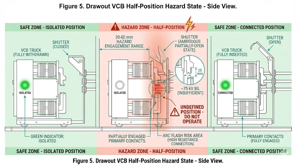
The half-position condition—where the VCB stops between defined positions—represents the most dangerous state in drawout switchgear operation. Field documentation indicates that a majority of racking-related incidents involve the breaker stalling in this intermediate zone where neither full isolation nor full connection exists.
During normal racking sequences, the VCB travels through a defined stroke of 150–200 mm between the isolated and connected positions. Half-position occurs when this travel stops prematurely, leaving primary disconnecting contacts partially engaged. At partial engagement depths of 30–80 mm, contact surfaces experience neither reliable electrical connection nor complete isolation.
Physics of Half-Position Danger
Partial air gaps between primary contacts and bus bar spouts create inadequate dielectric strength. At 12 kV nominal voltage, a 25 mm air gap provides approximately 75 kV BIL compared to the required 95 kV BIL for proper insulation coordination. Any switching attempt generates high-energy arcs that the shutter system cannot contain because shutters may also occupy an intermediate position—neither fully protecting contacts nor clear of the contact path.
According to IEC 62271-200, interlocking systems must prevent circuit breaker operation when racking mechanisms are not in designated positions. However, mechanical failures, contamination on guide rails, or insufficient racking force can defeat these protections. Contaminated guide rails with debris accumulation exceeding 2 mm thickness significantly increase half-position stall probability.
Contributing Factors
Half-position conditions typically result from:
IEEE C37.20.2 specifies that racking mechanisms shall include positive position indicators and mechanical stops at test and connected positions. Inspections reveal that worn position detent mechanisms—particularly those with degraded spring tension—fail to provide adequate tactile feedback to operators.
[Expert Insight: Recognizing Half-Position Warning Signs]
Alignment mechanisms ensure proper electrical and mechanical engagement during racking. The primary system consists of guide rails, positioning pins, and self-centering contacts maintaining dimensional tolerances within ±2 mm throughout the entire racking stroke. These mechanisms accommodate VCB units weighing 85–180 kg depending on voltage class and interrupting capacity.
Critical alignment parameters include:
These specifications prevent arcing damage during connection when current-carrying capacity reaches rated values. Misalignment commonly manifests through abnormal resistance during racking (exceeding 200 N push force), audible scraping sounds, and visible contact surface scoring.
Position Verification Methods
| Method | Indication Type | Reliability | Limitations |
|---|---|---|---|
| Mechanical flag indicator | Visual | High | Requires line-of-sight |
| Position limit switches | Electrical | High | Switch failure = false indication |
| Racking handle turn count | Operator judgment | Medium | Depends on training |
| Motor encoder feedback | Digital | High | Requires power supply |
The guide rail system utilizes hardened steel surfaces with roughness values below Ra 1.6 μm to minimize friction while maintaining structural rigidity. Self-aligning features compensate for installation variations and thermal expansion shifting component positions by 1–3 mm across the operating temperature range of -25°C to +55°C.
Interlocking systems form the mechanical logic foundation preventing unsafe racking sequences. These systems use physical barriers, key-exchange mechanisms, and position-sensing devices to enforce strict operational sequences according to IEC 62271-200 requirements.
Mechanical Interlock Chain
Properly functioning interlocks withstand operating forces of 200–500 N without deformation while maintaining positional accuracy within ±2 mm. The fundamental interlock chain for VCB racking includes:
Key-Exchange Systems
Kirk key and similar trapped-key systems provide sequence enforcement through physical key transfer. Each position releases a unique key required for subsequent operation. Key-exchange systems typically employ 3–5 unique key positions per VCB compartment. Key shear strength exceeds 15 kN to prevent unauthorized forcing, while lock mechanisms maintain 0.1 mm tolerance for reliable engagement.
Electrical Interlock Verification
The shutter position switch—typically a 2NO+2NC auxiliary contact arrangement—must change state within 2 mm of full shutter travel completion. The position-proving circuit prevents close commands when shutters remain partially open or when truck alignment deviates beyond 3° from centerline. In high-vibration environments such as mining installations, auxiliary contact gaps require inspection every 6 months versus the standard 12-month interval.
Systematic verification procedures prevent racking incidents. The following checklist consolidates field-proven practices applicable to most medium-voltage drawout switchgear.
Pre-Racking Verification
| Check | Method | Accept Criteria |
|---|---|---|
| Breaker OPEN status | Visual indicator + auxiliary contact | Both confirm OPEN |
| Control power state | Local/remote indication | Isolated or test mode per procedure |
| Compartment interior | Flashlight inspection | No debris, tools, foreign objects |
| Shutter condition | Visual + manual check if accessible | Free movement, closes fully |
| Guide rail condition | Visual inspection | No corrosion, obstruction, damage |
| Correct breaker for compartment | Nameplate verification | Serial number, ratings match |
During Racking Procedure
Post-Racking Verification
Critical Rule: If the racking handle does not release freely, the breaker has not reached a defined position. The mechanism design prevents handle release until the truck engages a position detent. Do not attempt any switching operation.
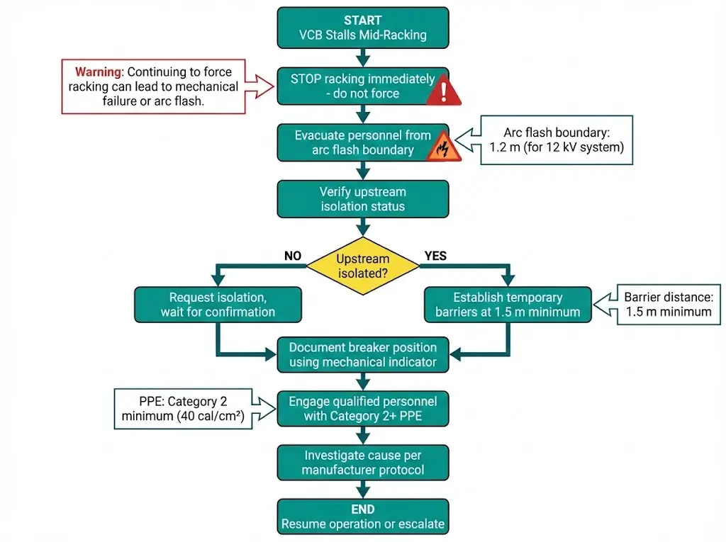
When a VCB stalls mid-racking, immediate response priorities focus on personnel safety and hazard isolation. According to IEEE 1584, incident energy levels increase dramatically when breakers occupy intermediate positions with compromised shutter coverage.
Immediate Actions
Half-position conditions create dual hazards: incomplete mechanical engagement compromises the breaker’s fault interruption capability, while partial shutter deployment leaves conductive components accessible. Restoration requires complete de-energization of the affected switchgear section before manual inspection following manufacturer-specific protocols.
XBRELE manufactures drawout vacuum circuit breakers with integrated safety systems designed for reliable field operation across demanding industrial environments.
Racking System Features
Engineering Support
XBRELE provides technical assistance including racking mechanism spare parts, field alignment verification guidance, and retrofit interlock upgrades for legacy switchgear installations. For specifications, replacement components, or new project support, contact the XBRELE vacuum circuit breaker engineering team.
What causes a drawout VCB to stall during racking?
Stalling typically results from guide rail contamination (debris accumulation exceeding 2 mm), worn roller bearings, misalignment between truck and compartment, or degraded lubrication on rail surfaces. Mechanical binding may also indicate bent guide pins or foreign objects in the racking path.
How do I verify shutter function before racking a VCB?
With the breaker withdrawn, visually confirm shutters are fully closed with no visible gaps. If the design permits access, manually deflect shutters slightly and confirm they snap back with positive spring force—typically 80–120 N. Shutters that close slowly or incompletely require maintenance before racking operations proceed.
What is the minimum safe distance during racking operations?
Arc flash boundaries for 12 kV switchgear typically range from 0.9–1.5 m depending on available fault current and clearing time. IEEE 1584 calculation methods determine site-specific boundaries. Personnel not directly performing racking should remain outside this boundary.
Can I rack a drawout VCB with the breaker in the closed position?
No. Mechanical interlocks physically prevent racking unless the breaker is open. Attempting to defeat this interlock creates immediate arc flash hazard because primary contacts would separate under load. Always verify open status through both the mechanical position indicator and auxiliary contact feedback before initiating racking.
How often should racking mechanisms be lubricated?
Guide rails and roller bearings typically require lubrication every 200 operations or annually, whichever occurs first. High-contamination environments (cement plants, mining operations, coastal substations) may require lubrication every 6 months. Use only manufacturer-specified lubricants—incompatible products can accelerate wear or create tracking paths.
What does position indicator flickering or blank display indicate?
Flickering or blank position indication signals that the breaker occupies an undefined position between mechanical detents. This half-position state requires immediate attention—do not attempt to close or trip the breaker. Investigate the cause before continuing racking in either direction.
Why won’t my racking handle release after reaching the connected position?
A handle that won’t release indicates the truck has not fully engaged the position detent. The breaker remains in a half-position even if the indicator suggests otherwise. Apply additional steady racking force (without jerking) to advance to full engagement, or investigate mechanical obstruction if resistance persists.
Authority reference: See IEC 62271-200 publication page for standard framework details.