Need Full Specifications?
Download our 2025 Product Catalog for detailed drawings and technical parameters of all switchgear components.
Get CatalogDownload our 2025 Product Catalog for detailed drawings and technical parameters of all switchgear components.
Get CatalogDownload our 2025 Product Catalog for detailed drawings and technical parameters of all switchgear components.
Get Catalog
Utilization categories classify electrical contactors according to the switching conditions they must withstand when controlling specific load types. For medium-voltage motor control applications, these categories define the current magnitude, power factor, and operational frequency a contactor experiences during making and breaking operations—parameters that directly determine whether a vacuum contactor will survive its intended service life or fail prematurely.
The International Electrotechnical Commission established this classification system in IEC 60947-4-1, originally for low-voltage contactors. Medium-voltage applications follow the same category definitions, with testing requirements adapted under IEC 62271-106 for high-voltage contactors and contactor-based motor starters.
Each utilization category specifies four critical parameters:
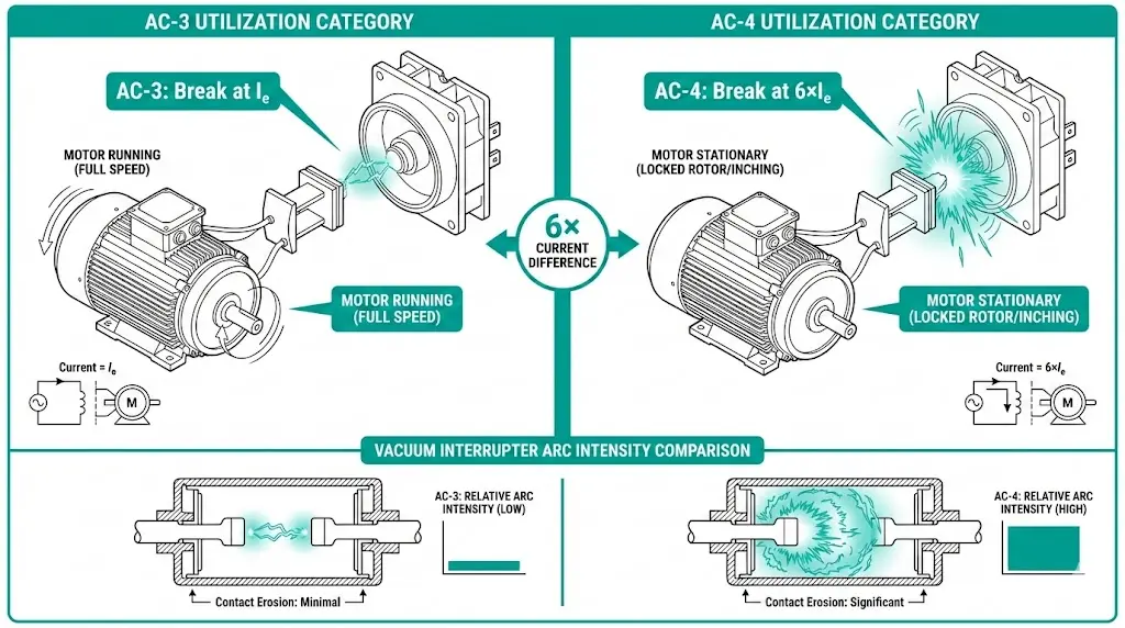
For squirrel-cage induction motors—the dominant motor type in medium-voltage industrial applications—two categories matter most: AC-3 and AC-4. The distinction centers on one question: at what point in the motor’s acceleration curve does the contactor interrupt current? The answer determines whether contact erosion accumulates gradually over hundreds of thousands of operations or rapidly within tens of thousands.
The fundamental distinction between AC-3 and AC-4 lies in the electrical stress imposed at the moment of contact separation. AC-3 applies to starting squirrel-cage motors and switching them off while running at normal speed. AC-4 covers starting, plugging, inching, and reversing operations where contacts must repeatedly interrupt locked-rotor current.
AC-3: Normal Duty Motor Switching
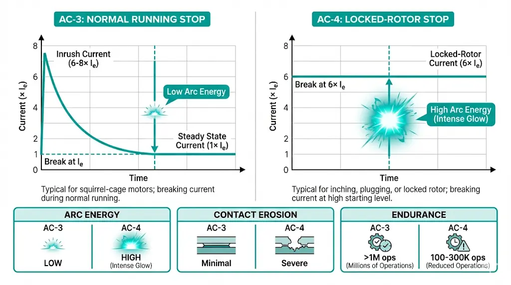
When a motor reaches full speed, current drops to rated operational levels before the vacuum contactor opens. According to IEC 60947-4-1 Section 4.3.5.1, AC-3 rated contactors must handle making currents of approximately 6× rated operational current (Ie) during motor start, but interruption occurs at only 1× Ie. The power factor during breaking typically ranges from 0.85 to 0.90, reducing arc energy substantially during contact separation.
In field deployments across petrochemical facilities and water treatment plants, AC-3 represents the most common switching scenario. The motor’s back-EMF significantly reduces recovery voltage appearing across the vacuum gap. Field testing on 7.2 kV vacuum contactors shows break currents ranging from 200 A to 400 A for typical motor applications, with contact gap distances of 6–10 mm providing adequate dielectric strength.
AC-4: Severe Duty Motor Switching
Under AC-4 conditions, the vacuum contactor must break current at 6× Ie with a power factor of only 0.35 to 0.40. No back-EMF assistance exists because the rotor remains stationary or is reversing. The vacuum interrupter must extinguish arcs with full prospective current flowing through CuCr contact surfaces at full line voltage.
The arc energy relationship explains the severity:
Arc Energy ∝ I² × t × (1 – cos φ)
The low power factor means current and voltage are significantly out of phase, with current zero crossings occurring under higher recovery voltage stress. This translates to intense arc heating, greater copper-chromium material erosion per operation, and faster accumulation of contact gap wear.
[Expert Insight: Field Observations on AC-3/AC-4 Performance]
The IEC framework defines multiple AC utilization categories, each addressing specific load types and switching conditions. For medium-voltage vacuum contactors controlling squirrel-cage induction motors, AC-3 and AC-4 dominate specifications, though understanding the complete family provides context.
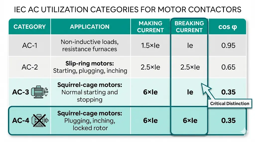
| Category | Application | Making Current | Breaking Current | cos φ |
|---|---|---|---|---|
| AC-1 | Non-inductive or slightly inductive loads | 1.5 × Ie | Ie | 0.95 |
| AC-2 | Slip-ring motors: starting, switching off | 2.5 × Ie | 2.5 × Ie | 0.65 |
| AC-3 | Squirrel-cage motors: starting, running stop | 6 × Ie | Ie | 0.35 |
| AC-4 | Squirrel-cage motors: plugging, inching, jogging | 6 × Ie | 6 × Ie | 0.35 |
The critical distinction sits in the breaking current column. AC-3 assumes interruption of a motor running at near-full speed—current has dropped to rated operational levels. AC-4 assumes interruption at or near locked-rotor conditions: six times higher current with significantly more arc energy to extinguish.
AC-2 applies specifically to slip-ring (wound-rotor) motors, which have different starting characteristics and are less common in modern MV installations. AC-1 covers resistive and lightly inductive loads such as heating elements—rarely the primary concern for vacuum contactor selection in motor control applications.
Critical AC-3 parameters include: electrical endurance ≥ 1 × 10⁶ operating cycles at rated current, mechanical endurance up to 3 × 10⁶ operations, and contact erosion rates typically < 0.1 μg per ampere-second of arc duration.For engineers specifying MV vacuum contactors, the question becomes straightforward: will this motor ever be stopped before reaching full speed? If yes, AC-4 applies. If the motor always runs to speed before stopping, AC-3 suffices.
The vacuum interrupter’s CuCr (copper-chromium) contacts bear the full burden of AC-4 duty’s electrical severity. Understanding the wear mechanism explains why utilization category selection directly impacts maintenance intervals and lifetime cost.
During AC-3 interruption, the diffuse vacuum arc spreads across the contact face, distributing thermal energy relatively evenly. Current magnitude is low (1× Ie), and the favorable power factor means arc duration before current zero is brief. Contact material loss per operation remains minimal.
AC-4 conditions create a fundamentally different arc behavior. At 6× Ie with 0.35 power factor, the arc transitions from diffuse to constricted mode. Energy concentrates in localized spots on the contact surface, causing:
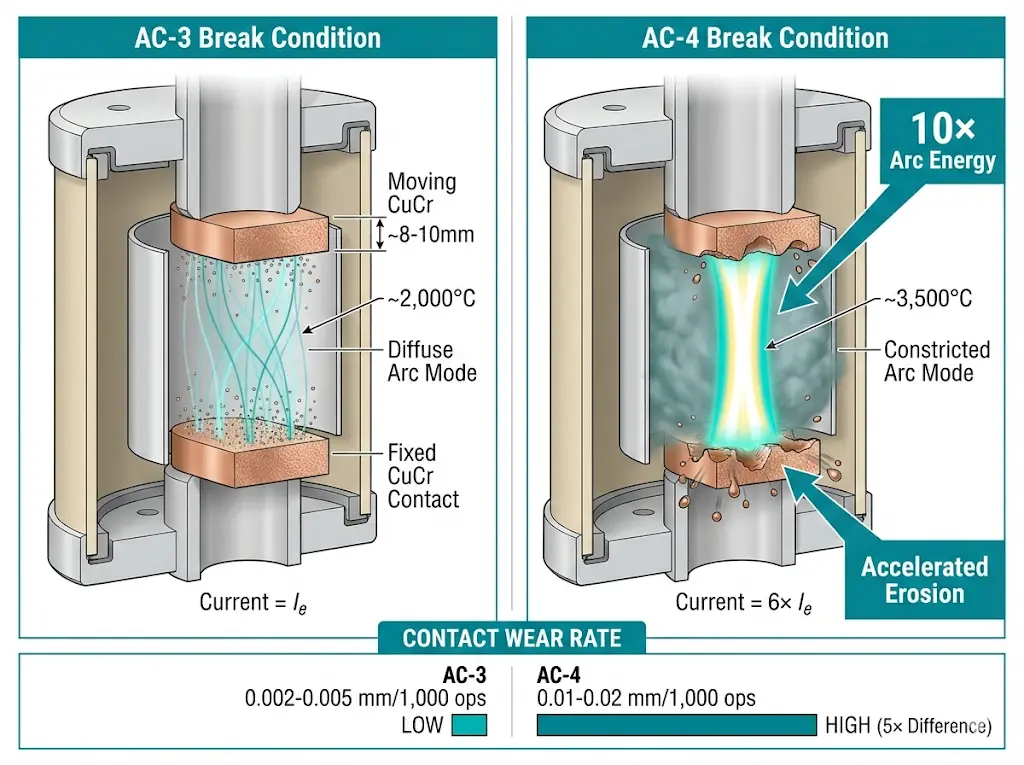
Standard CuCr contacts with 25–50% chromium content provide the baseline for motor switching duty. For severe AC-4 service, manufacturers may specify:
The contact gap—typically 8–12 mm for MV contactors rated 7.2 kV—must maintain adequate dielectric strength even as erosion accumulates. Vacuum level below 10⁻³ Pa enables rapid deionization of metal vapor arcs, but repeated high-energy interruptions gradually degrade the internal environment through shield contamination and getter exhaustion.
For a deeper understanding of vacuum interrupter construction and arc extinction physics, see our complete guide: What Is a Vacuum Interrupter and How Does It Work?
[Expert Insight: Contact Life Management]
Matching utilization category to actual duty cycle prevents both premature failure and unnecessary oversizing. The application profile—not the motor nameplate alone—determines correct specification.
Typical AC-3 Applications in MV Systems:
These applications share a common characteristic: the motor accelerates to operating speed before the stop command. The contactor interrupts only rated current under favorable power factor conditions.
Typical AC-4 Applications in MV Systems:
Mining operations present a particular challenge. Conveyor systems may operate primarily in AC-3 mode but require occasional jogging for maintenance positioning. A contactor specified purely for AC-3 duty will experience accelerated wear during these AC-4 cycles.
Mixed Duty Calculation
Real-world applications often combine both duty types. The IEC approach allows calculating equivalent wear:
Equivalent AC-3 operations = AC-3 operations + (k × AC-4 operations)
The multiplier k typically ranges from 3 to 10 depending on manufacturer testing data. For a crane performing 50 normal start/stops and 5 inching cycles daily, the equivalent AC-3 wear might be 50 + (5 × 8) = 90 operations per day rather than 55.
Explore our complete range of vacuum contactors engineered for both AC-3 and AC-4 service: Vacuum Contactor Manufacturer
Proper category selection requires analyzing the actual operating profile rather than applying generic safety factors. Four questions guide the assessment:

The Derating Reality
A contactor rated for AC-3 duty cannot simply serve AC-4 applications at the same current rating. Standard approaches include:
| Parameter | AC-3 Rating | AC-4 Rating (Same Frame) |
|---|---|---|
| Rated operational current | 400 A | 200 A typical |
| Electrical endurance | 500,000–2,000,000 ops | 100,000–500,000 ops |
| Contact erosion per 1,000 ops | 0.002–0.005 mm | 0.01–0.02 mm |
Selecting a larger frame size maintains the required current rating under AC-4 conditions. Some manufacturers offer enhanced contact materials—tungsten-copper (WCu) or silver-tungsten carbide (AgWC)—for severe duty applications where frame upsizing is impractical.
Standards Verification
Manufacturers must demonstrate compliance through type testing per IEC 62271-106 [VERIFY STANDARD: confirm current edition applies to specific voltage class]. Type tests verify making and breaking capacity at rated category values, electrical endurance through reduced test cycles extrapolated to rated life, and dielectric withstand after switching operations.
When preparing specifications for vacuum contactor procurement, refer to our detailed guide: VCB RFQ Checklist: Technical Requirements
XBRELE manufactures medium-voltage vacuum contactors rated from 3.6 kV to 12 kV, engineered for reliable performance across both AC-3 and AC-4 utilization categories. Our vacuum interrupters feature optimized CuCr contact materials with controlled chromium content for consistent arc erosion characteristics throughout operational life.
Each contactor undergoes routine testing to verify power frequency withstand voltage, main circuit resistance, and mechanical operation parameters. Type test reports referencing specific utilization categories are available upon request, providing the documentation required for project specifications and quality assurance programs.
For applications involving mixed AC-3/AC-4 duty or unusual operating profiles, our engineering team provides technical consultation to determine appropriate sizing and contact material selection. Whether your application involves standard pump motor control or demanding crane operations with frequent inching cycles, proper utilization category matching ensures reliable switching performance and predictable maintenance intervals.
For guidance on installation environment considerations, see our selection resource: Indoor vs Outdoor VCB Selection Guide
For complete testing requirements and utilization category definitions, refer to the standards published by the International Electrotechnical Commission.
Q1: What determines whether my application requires AC-3 or AC-4 rated contactors?
A1: The key factor is whether the motor reaches full operating speed before the contactor opens. If the motor always accelerates completely before stopping, AC-3 applies. If operations include jogging, inching, plugging, or any stopping before full speed, AC-4 requirements govern contactor selection.
Q2: How significantly does AC-4 duty reduce vacuum contactor service life compared to AC-3?
A2: Electrical endurance under AC-4 conditions typically falls to 10–30% of AC-3 life for identical contactor frames, primarily due to the sixfold increase in breaking current and associated arc energy at each operation.
Q3: Can I apply a safety factor to an AC-3 rated contactor for occasional AC-4 operations?
A3: Occasional AC-4 operations require equivalent wear calculations rather than simple safety factors. Multiply the number of AC-4 cycles by 3–10 (per manufacturer data) and add to AC-3 operations to estimate true contact wear accumulation.
Q4: What contact materials best suit severe AC-4 duty in MV vacuum contactors?
A4: High-chromium CuCr alloys (50–75% Cr) with grain-refined microstructures provide superior arc erosion resistance, while spiral-field contact geometries distribute arc energy across the contact face to reduce localized wear.
Q5: How do I verify that a vacuum contactor is properly rated for my specified utilization category?
A5: Request type test certificates referencing the specific utilization category and current rating for your application. Testing per IEC 62271-106 should demonstrate making capacity, breaking capacity, and electrical endurance at the declared category.
Q6: Does operating voltage affect utilization category requirements?
A6: The utilization category definitions apply consistently across voltage classes, but higher system voltages increase recovery voltage stress during interruption, making proper category selection even more critical for 7.2 kV and 12 kV applications.
Q7: What maintenance indicators suggest a contactor has exceeded its rated utilization category duty?
A7: Increased contact resistance measurements, longer arcing times during interruption, visible contact erosion beyond manufacturer limits, and reduced dielectric withstand capability all indicate accumulated stress potentially exceeding design assumptions for the rated category.