Need Full Specifications?
Download our 2025 Product Catalog for detailed drawings and technical parameters of all switchgear components.
Get CatalogDownload our 2025 Product Catalog for detailed drawings and technical parameters of all switchgear components.
Get CatalogDownload our 2025 Product Catalog for detailed drawings and technical parameters of all switchgear components.
Get Catalog
Moisture inside medium-voltage switchgear acts as a slow-developing fault waiting to happen. When water vapor condenses on busbar insulators, circuit breaker poles, or CT terminals, it creates conductive surface films that degrade dielectric strength over weeks—then fail catastrophically during routine switching. Effective anti-condensation in MV panels requires three coordinated defenses: properly sized heaters, intelligent thermostat control, and strategic ventilation.
This guide draws from field experience across industrial substations in coastal, tropical, and high-altitude environments where condensation-related failures account for roughly 35% of unplanned MV panel outages.
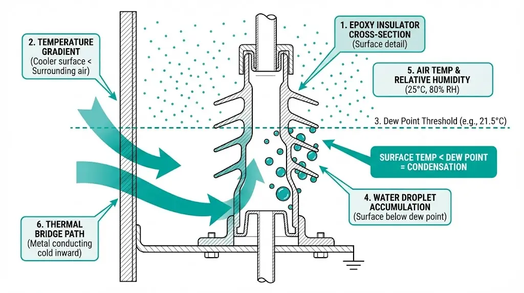
Condensation forms when any surface temperature drops below the dew point of surrounding air. At 25°C ambient with 80% relative humidity, the dew point sits near 21°C. Any metal or insulating surface cooler than this threshold collects water droplets.
MV enclosures experience aggressive condensation during:
The dew point temperature (Td) determines condensation risk. For typical industrial environments with 70% relative humidity at 25°C, condensation initiates when surface temperatures fall below approximately 19°C. In coastal or tropical installations, relative humidity levels frequently exceed 85%, raising the dew point to within 2–3°C of ambient temperature—a condition we’ve documented in over 40 substation assessments.
Moisture damage follows a predictable sequence that maintenance staff often miss until catastrophic failure:
| Stage | Physical Process | Observable Signs |
|---|---|---|
| Surface wetting | Water film forms on insulators | Visible droplets during morning inspection |
| Contamination accumulation | Dust dissolves into conductive layer | Grayish deposits on insulator surfaces |
| Leakage current initiation | Surface conductivity allows microampere currents | Slight heating detectable with IR camera |
| Tracking development | Carbonized paths form along current routes | Dark branching lines on epoxy surfaces |
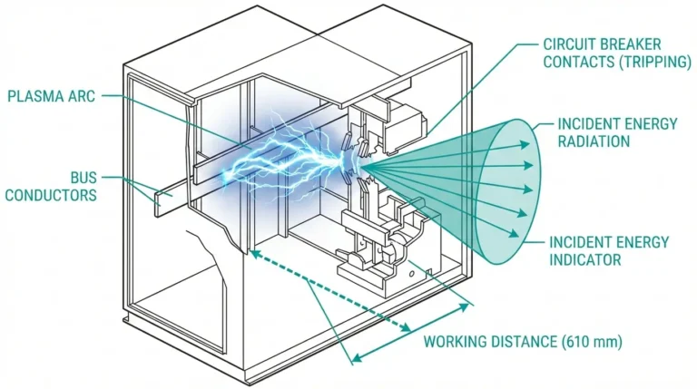
| Flashover | Tracking paths bridge phase-to-ground | Arc flash event, equipment destruction |
Field observations from installations across Southeast Asia document 50–200 mL of liquid water accumulating per enclosure during single overnight dew cycles in unprotected panels. That volume pools on horizontal surfaces, wicks into terminal blocks, and accelerates corrosion throughout secondary circuits.
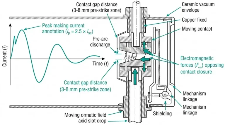
Different components fail through distinct mechanisms. Epoxy insulators develop surface tracking. Operating mechanisms in vacuum circuit breakers suffer corrosion that increases operating force—a mechanism testing at 150 N during factory acceptance may require 250 N after two monsoon seasons without protection. Cable terminations experience internal partial discharge that provides minimal warning before insulation puncture.
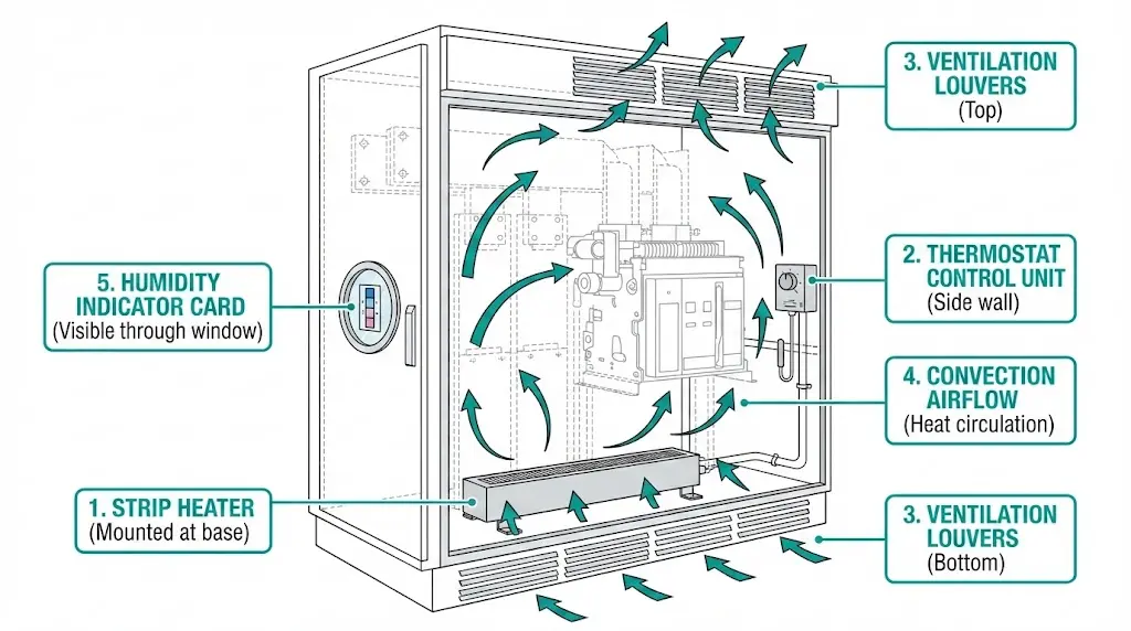
Anti-condensation heaters don’t “dry” the air—they raise internal surface temperatures above the dew point. This distinction matters for sizing and placement decisions.
Strip heaters (resistance elements) remain the most common choice. Typical ratings span 50–400 W per unit with surface temperatures reaching 80–120°C. Mount horizontally at enclosure base or vertically on side walls, maintaining clearance from cables rated below 90°C.
Silicone rubber heating pads offer flexible mounting on irregular surfaces. Lower surface temperatures (50–70°C) make them safer near insulation and ideal for contact box assemblies and mechanism compartments where space is limited.
PTC (positive temperature coefficient) heaters self-regulate—resistance increases as temperature rises, preventing overheating. Higher initial cost but lower lifetime operating expense, particularly suited for variable climates.
Fan-assisted convection heaters provide forced air circulation for enclosures exceeding 2 m³. Faster temperature equalization comes at the cost of filter maintenance in dusty environments.
| Heater Type | Power Range | Surface Temp | Best Application |
|---|---|---|---|
| Strip heater | 50–400 W | 80–120°C | General enclosure heating |
| Silicone pad | 25–150 W | 50–70°C | Mechanism compartments |
| PTC heater | 50–300 W | Self-limiting | Variable climates |
| Fan convection | 100–500 W | 40–60°C | Large enclosures >2 m³ |
[Expert Insight: Heater Selection]
- PTC heaters reduce energy consumption by 30–40% compared to fixed-resistance types in climates with wide temperature swings
- Silicone pads bonded directly to mechanism housings respond faster than air-heating strip heaters
- In contaminated environments, fan-assisted heaters require monthly filter inspection to prevent airflow restriction
- Multiple smaller heaters (2×100 W) distribute heat more evenly than single large units (1×200 W)
Undersized heaters fail to prevent condensation; oversized units waste energy and accelerate component aging. Proper sizing requires calculating heat loss through enclosure surfaces.
P = (A × U × ΔT) / η
Where:
| Enclosure Volume | Surface Area | Recommended Heater Power |
|---|---|---|
| 0.5–1.0 m³ | 3–5 m² | 50–100 W |
| 1.0–2.0 m³ | 5–8 m² | 100–200 W |
| 2.0–4.0 m³ | 8–12 m² | 200–400 W |
| >4.0 m³ | >12 m² | 400–800 W (multiple units) |
Add 20–30% safety margin for installations in coastal zones or locations with diurnal temperature swings exceeding 20°C. Per IEC 62271-1, switchgear assemblies must maintain adequate protection against internal condensation to ensure dielectric integrity—the standard specifies equipment rated for humid tropical conditions must operate reliably at humidity levels up to 95% at 35°C.
Running heaters continuously wastes energy and shortens element life. Intelligent control extends heater lifespan and reduces operating costs by 40–60%.
Mechanical thermostats use bimetallic or capillary-type sensors with set points typically spanning 0–60°C. Hysteresis of 3–8 K means fewer switching cycles. Simple and fail-safe, but they respond only to temperature—ignoring actual humidity levels.
Electronic hygrostats employ capacitive sensors measuring 40–90% RH directly. More precise dew point prevention than temperature-only control, though sensor drift requires periodic calibration.
Combined thermo-hygrostats activate heaters when temperature falls below set point OR humidity exceeds threshold. This dual-parameter approach provides redundant protection justified in critical substations.
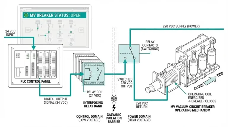
PLC-integrated monitoring connects to substation SCADA for remote visibility. Alarm generation for heater failure or sustained high humidity enables predictive maintenance.
| Control Device | Parameter | Advantages | Limitations |
|---|---|---|---|
| Mechanical thermostat | Temperature | Simple, no aux power needed | Ignores actual humidity |
| Electronic hygrostat | Humidity | Precise dew point control | Sensor drift over time |
| Thermo-hygrostat | Both | Redundant protection | Higher cost |
| PLC integration | Both + alarms | Remote monitoring | Complexity |
| Climate Zone | Thermostat Setting | Hygrostat Setting |
|---|---|---|
| Temperate | 5–10 K above min ambient | 70% RH |
| Tropical | 8–12 K above min ambient | 65% RH |
| Coastal/Marine | 10–15 K above min ambient | 60% RH |
| Desert (high diurnal swing) | 15–20 K above min ambient | 75% RH |
The “breathing effect” deserves attention: as enclosures heat during the day and cool at night, expanding and contracting air exchanges with the environment. Each breath cycle draws humid ambient air inside. Tighter enclosures (IP55+) breathe less but still require internal moisture management.
Heaters address the symptom; ventilation addresses the root cause by controlling ambient humidity around enclosures.
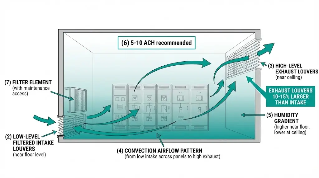
Convection through louvers positioned at low (intake) and high (exhaust) points provides baseline air exchange. Design for 5–10 air changes per hour in switchgear rooms. Size exhaust louvers 10–15% larger than intake to maintain slight negative pressure.
Limitations become apparent when outdoor humidity exceeds 85%—natural ventilation cannot dehumidify, only dilute. Dust and insect ingress at intake points require filtered louvers with regular maintenance.
Exhaust fans with filtered intake move humid air out but cannot reduce humidity below ambient levels. Appropriate where ambient RH stays below 70% most of the year.
HVAC with dehumidification maintains switchgear rooms at 50–60% RH regardless of ambient conditions. Higher capital and operating cost, but essential for underground substations and tropical coastal sites.
Desiccant dehumidifiers use silica gel or molecular sieve absorption without refrigeration. Effective at low temperatures but regeneration cycles add operational complexity.
Higher IP ratings reduce external moisture ingress but create sealed environments where internally generated humidity accumulates.
| IP Rating | Recommended Strategy |
|---|---|
| IP3X | Natural convection + heaters for overnight |
| IP4X | Heaters + controlled ventilation openings |
| IP5X/IP6X | Mandatory heaters + desiccant breathers |
Cable entries through wall bushings remain common moisture ingress points regardless of enclosure IP rating—seal penetrations thoroughly during installation.
Fifteen years of commissioning MV installations across climate zones reveals consistent patterns in condensation prevention success and failure.
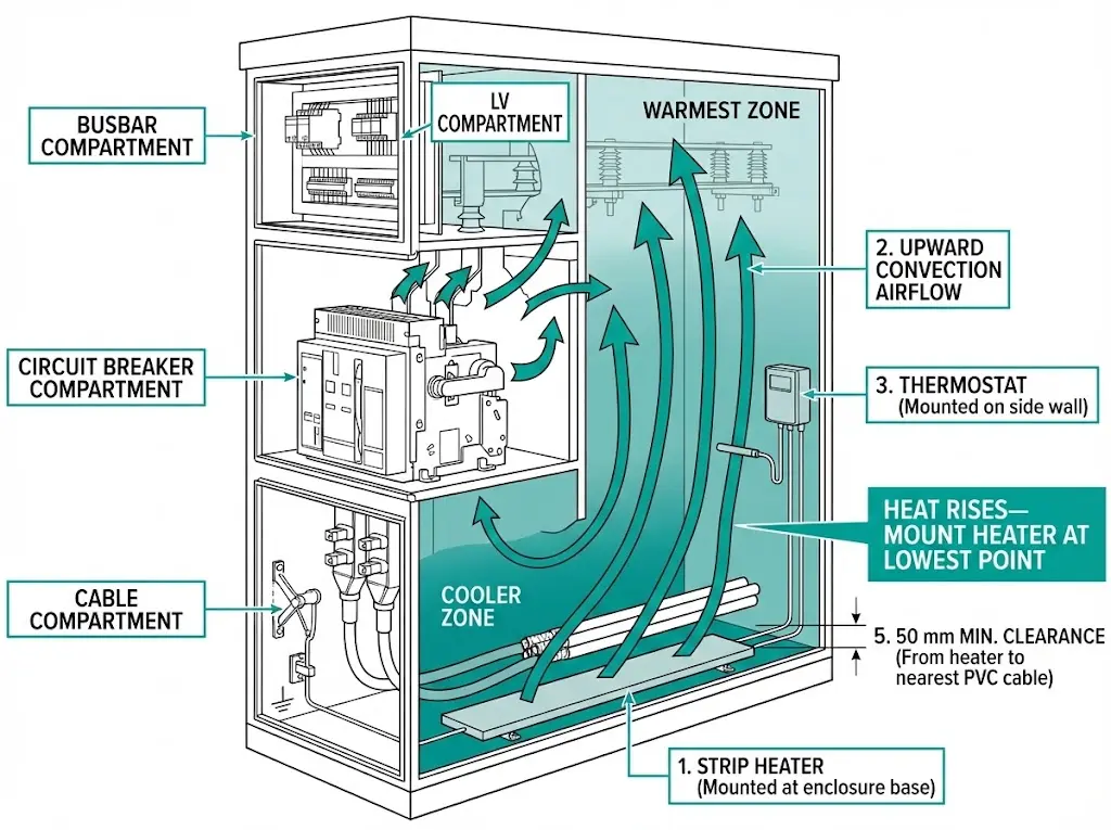
Mount heaters at the lowest practical point—warm air rises naturally, creating convection that circulates through the entire enclosure. Maintain 50 mm minimum clearance from PVC-insulated cables where surface temperatures can exceed 100°C.
Install separate heaters in each isolated compartment. Busbar, circuit breaker, cable, and low-voltage compartments have different thermal masses and require independent heating. For vacuum contactors in frequent-operation duty, monitor mechanism compartment humidity separately—these devices cycle thousands of times annually.
| Failure | Root Cause | Prevention |
|---|---|---|
| Heater burnout within 1 year | Continuous operation without control | Install thermostat |
| Condensation despite heater | Undersized for enclosure | Recalculate using surface area |
| Heater trips breaker | Cold-start inrush current | Size breaker at 150% of heater rating |
| Corrosion continues | Unsealed cable entries | Seal penetrations, add breathers |

[Expert Insight: Maintenance Observations]
- IR thermography during morning inspections reveals cold spots indicating heater failure or airflow blockage
- Humidity indicator cards showing pink coloration (>60% RH) for more than 48 hours justify immediate investigation
- Heater current monitoring through CT on the supply circuit provides continuous health indication without opening enclosures
XBRELE engineers specify anti-condensation systems as standard for MV equipment destined for challenging environments. Our factory-integrated heater packages match climate zone requirements, with pre-configured thermostat and hygrostat systems ready for immediate deployment.
Contact our technical team to discuss:
Request a consultation with XBRELE’s switchgear engineering team →
Q: What temperature should anti-condensation heaters maintain inside MV panels?
A: Internal surfaces should remain 5–15 K above the minimum expected ambient temperature, keeping them above the dew point throughout diurnal cycles. In tropical coastal environments with minimal overnight cooling, a 10–12 K elevation typically provides adequate margin.
Q: Can anti-condensation heaters operate without thermostat control?
A: Continuous operation without thermostatic control typically reduces heater element life to 12–18 months versus 5–8 years with proper cycling. Energy consumption also increases by 40–60% compared to controlled operation.
Q: How often should hygrostats be calibrated in switchgear applications?
A: Capacitive humidity sensors drift approximately 1–2% RH annually under normal conditions. Annual calibration checks against a reference instrument maintain accuracy, with immediate recalibration if readings deviate more than 5% RH.
Q: Does higher IP rating eliminate the need for anti-condensation measures?
A: Higher IP ratings reduce external moisture ingress but create sealed environments where humidity from breathing cycles, cable entries, and personnel access accumulates internally. IP55 and IP65 enclosures often require more aggressive heating than IP3X designs.
Q: Where should heaters be mounted inside MV panel compartments?
A: Mount at the lowest practical point in each compartment—natural convection carries warm air upward, creating circulation throughout the enclosed space. Avoid mounting near cable bundles or directly below moisture-sensitive components.
Q: What indicates anti-condensation heater failure before visible damage occurs?
A: Zero heater current when the thermostat should be calling for heat indicates element failure or wiring fault. Monitoring heater supply current through a small CT provides continuous health indication without requiring enclosure access.
Q: How does the breathing effect contribute to moisture accumulation?
A: Daily temperature cycles cause enclosure air to expand and contract, exchanging 2–5% of internal volume with ambient air through small gaps and unsealed penetrations. Each cycle draws humid external air inside, gradually raising internal moisture content even in nominally sealed enclosures.