هل تحتاج إلى المواصفات الكاملة؟
قم بتنزيل كتالوج منتجاتنا لعام 2025 للحصول على رسومات تفصيلية ومعايير تقنية لجميع مكونات المفاتيح الكهربائية.
احصل على الكتالوجقم بتنزيل كتالوج منتجاتنا لعام 2025 للحصول على رسومات تفصيلية ومعايير تقنية لجميع مكونات المفاتيح الكهربائية.
احصل على الكتالوجقم بتنزيل كتالوج منتجاتنا لعام 2025 للحصول على رسومات تفصيلية ومعايير تقنية لجميع مكونات المفاتيح الكهربائية.
احصل على الكتالوج
اختر كابلات التحكم للوحات الجهد المتوسط عن طريق التدريع، وتصنيف الحرائق، والتوجيه، والإنهاء، والاختبار، ومتطلبات التوافق الكهرومغناطيسي (EMC).
تعمل كابلات التحكم في لوحات الجهد المتوسط (MV) بمثابة الجهاز العصبي للبنية التحتية الكهربائية، حيث تنقل الإشارات الهامة للحماية والقياس والمراقبة ووظائف الأتمتة. في حين أن كابلات الطاقة غالبًا ما تحظى بالاهتمام الأساسي أثناء تصميم النظام، فإن اختيار كابل التحكم يؤثر بشكل مباشر على موثوقية النظام وسلامة الأفراد والاستمرارية التشغيلية. يمكن أن يؤدي فشل كابل تحكم واحد إلى جعل أنظمة الحماية غير فعالة، مما قد يؤدي إلى تلف المعدات أو أعطال كارثية.
بعد أن أمضيت أكثر من خمسة عشر عامًا في تشغيل واستكشاف أخطاء مجموعة المفاتيح الكهربائية ذات الجهد المتوسط واستكشاف الأخطاء وإصلاحها في المنشآت الصناعية ومحطات الطاقة والمحطات الفرعية للمرافق، شهدت عن كثب كيف أن الاختيار غير السليم لكابلات التحكم يخلق مشاكل خبيثة تظهر بعد أشهر أو سنوات من التركيب. التداخل الكهرومغناطيسي الذي يتسبب في رحلات مرحل مزعجة، والكابلات المتضررة من الحرائق التي تنشر اللهب بين المقصورات، والتوصيلات سيئة الإنهاء التي تتسبب في حدوث أعطال متقطعة - هذه المشكلات تشترك في جذور مشتركة: عدم الاهتمام الكافي بمواصفات كابل التحكم أثناء مرحلة التصميم.
يعالج هذا الدليل الشامل الاعتبارات الأساسية لاختيار كابل التحكم في لوحات الجهد المتوسط المصنف من 1 كيلو فولت إلى 52 كيلو فولت، ويغطي متطلبات التدريع، وتصنيفات أداء الحريق، وأفضل ممارسات التوجيه، وتقنيات الإنهاء التي تضمن سلامة النظام على المدى الطويل.
| نوع الدائرة | هيكل الكابل الموصى به | الوجبات الرئيسية لتحسين محركات البحث/المواصفات الرئيسية |
|---|---|---|
| الدوائر الثانوية للتصوير المقطعي المحوسب والدوائر الثانوية للتيار المتردد | نحاس مجدول من النحاس، ودرع مجدول بالكامل، وأنوية محددة بوضوح | إعطاء الأولوية لدقة العبء وتحمل الدائرة القصيرة واستمرارية الدرع. |
| دوائر التعثر، والإغلاق، ودوائر الشحن الزنبركي | 2.5 مم² نحاس مجدول 2.5 مم² مع عزل قوي وحلقات | الحجم المناسب لتدفق الملف، وانخفاض الجهد، والمتانة الميكانيكية. |
| الإشارات التناظرية وأجهزة الاستشعار | أزواج أو ثلاثية محمية بشكل فردي مع توجيه منخفض التشويش | افصل عن تبديل العابرين والدروع الأرضية عمداً. |
| إشارات Ethernet و RS-485 و IEC 61850 | كابل اتصال ذو مقاومة محكومة مع إنهاء EMC | حافظ على استمرارية الدرع من خلال الغدد ولوحات التوصيل والمفاتيح. |
تحمل كبلات التحكم في لوحات MV أنواعاً مختلفة من الإشارات، ويتطلب كل منها خصائص كابل محددة:
إشارات تناظرية منخفضة المستوى (حلقات التيار 4-20mA، ودوائر RTD، ومخرجات المزدوجات الحرارية) تتطلب مناعة فائقة ضد الضوضاء ومقاومة ثابتة للموصل. تربط هذه الدوائر عادةً محولات التيار، ومحولات الجهد، ومستشعرات درجة الحرارة، وأجهزة إرسال الضغط بمرحلات الحماية وأنظمة SCADA.
إشارات رقمية (ملامسات المرحلات، والمفاتيح الإضافية، ومفاتيح التبديل الإضافية، ومؤشرات الموضع) تعمل بمستويات جهد أعلى (24-125 فولت تيار مستمر أو 110-240 فولت تيار متردد) مع قدرة أكبر على تحمل الضوضاء. ومع ذلك، تصبح سعة الكابل أمرًا بالغ الأهمية للمسافات الأطول التي تتجاوز 100 متر، خاصةً مع مدخلات مرحلات الحالة الصلبة.
دوائر الاتصالات (Ethernet، و RS-485 التسلسلية، و IEC 61850 GOOSE للرسائل) تتطلب خصائص مقاومة مضبوطة وتكوينات تدريع محددة للحفاظ على سلامة البيانات عند سرعات نقل تصل إلى 100 ميغابت في الثانية أو أعلى.
يتجاوز تحديد حجم الموصلات لكابلات التحكم مجرد حسابات القدرة على حمل التيار. وتشمل الاعتبارات الأساسية ما يلي:
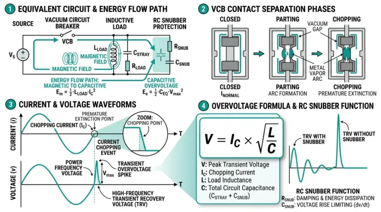
تمثل مجموعة المفاتيح الكهربائية ذات الجهد المتوسط بيئة كهرومغناطيسية صعبة. وتشمل مصادر التداخل الرئيسية ما يلي:
التداخل الذي تم إجراؤه تنشأ من توافقيات تردد الطاقة، والتبديل العابر للترددات، والتبديل العابر للترددات، وارتفاع الجهد الأرضي أثناء ظروف العطل. تولد محركات المحركات، ومحولات الطاقة الإلكترونية، وتبديل بنك المكثفات ضوضاء عالية التردد موصلة عالية التردد تقترن بدوائر التحكم من خلال مسارات التأريض المشتركة.
التداخل الإشعاعي تنبثق من قضبان الناقل التي تحمل تيارات عالية، وأحداث الوميض القوسي، ونشاط التفريغ الجزئي، ومصادر الترددات الراديوية القريبة. يمكن للمجالات المغناطيسية المحيطة بموصلات الناقل أن تستحث الفولتية في حلقات كابل التحكم بما يتجاوز عتبات تشغيل مرحل الحماية.
التداخل الكهروستاتيكي الاقتران بالسعة من الموصلات ذات الجهد العالي إلى كابلات التحكم المجاورة، وهو ما يمثل مشكلة خاصة في المفاتيح الكهربائية المعزولة بالغاز (GIS) حيث تمر كابلات التحكم بالقرب من المقصورات المملوءة بـ SF6.
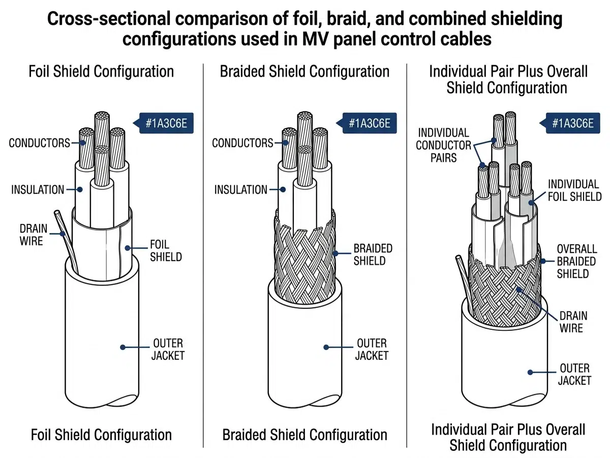
دروع رقائق معدنية (صفائح من الألومنيوم والبوليستر) توفر تغطية 100% وتوهينًا ممتازًا عالي التردد أعلى من 1 ميجاهرتز. يقلل الهيكل الرقيق من قطر الكابل ولكنه يوفر رفضًا محدودًا للمجال المغناطيسي منخفض التردد. تعمل الدروع الرقيقة على النحو الأمثل لدوائر الاتصالات والمدخلات التناظرية عالية المقاومة.
دروع مضفرة (جديلة نحاسية معلبة، تغطية 85-95% عادةً) توفر تدريعًا مغناطيسيًا فائقًا منخفض التردد ومرونة ميكانيكية أفضل من بدائل الرقائق المعدنية. إن مقاومة النقل المنخفضة عند الترددات الأقل من 1 ميجاهرتز تجعل الدروع المضفرة مفضلة للدوائر الثانوية للتصوير المقطعي المحوسب/التصوير المقطعي المحوسب وإشارات الحماية الحرجة.
الدروع المدمجة (رقائق معدنية بالإضافة إلى جديلة) توفر حماية عريضة النطاق عبر طيف التردد. على الرغم من أن التدريع المركب أكثر تكلفة، إلا أنه يثبت أنه ضروري للدوائر التناظرية الحساسة في البيئات عالية التداخل، مثل أنظمة مراقبة التفريغ الجزئي التي تعمل بالقرب من ناقلات الجهد المتوسط.
أزواج/ثلاثيات محمية بشكل فردي منع التداخل بين الدوائر داخل الكابل نفسه، وهو أمر بالغ الأهمية عند مزج الإشارات التناظرية والرقمية. تسمح هذه البنية لأنواع متعددة من الإشارات بمشاركة مسار كابل مشترك مع الحفاظ على سلامة الإشارة.
تثير فلسفة تأريض الدروع جدلاً كبيراً بين المهندسين. واستناداً إلى قياسات ميدانية واسعة النطاق ومعايير الصناعة (IEEE 1143، IEC 62271-1)، أوصي بالنهج التالي:
تأريض أحادي النقطة في طرف اللوحة يمنع التيارات الدائرية من خلال موصلات الدرع، وهو مثالي للدوائر التناظرية منخفضة التردد حيث يمكن أن تؤدي التيارات المستحثة إلى حدوث أخطاء في القياس. تتطلب هذه التقنية عزل مناسب للدرع في الطرف البعيد.
تأريض متعدد النقاط يوفر رفضًا فائقًا للضوضاء عالية التردد من خلال إنشاء مسار منخفض المقاومة للأرض في مواقع متعددة. يناسب هذا النهج دارات الاتصالات الرقمية والتركيبات التي تمثل فيها العابرون الناجمون عن الصواعق مخاوف.
التأريض الهجين يوصل الدروع مباشرة في طرف اللوحة مباشرة ومن خلال مكثفات الالتفافية عالية التردد (عادةً 10-100nF) في الأطراف البعيدة. يمنع هذا التكوين التيارات الدائرية منخفضة التردد مع الحفاظ على فعالية التدريع عالي التردد.
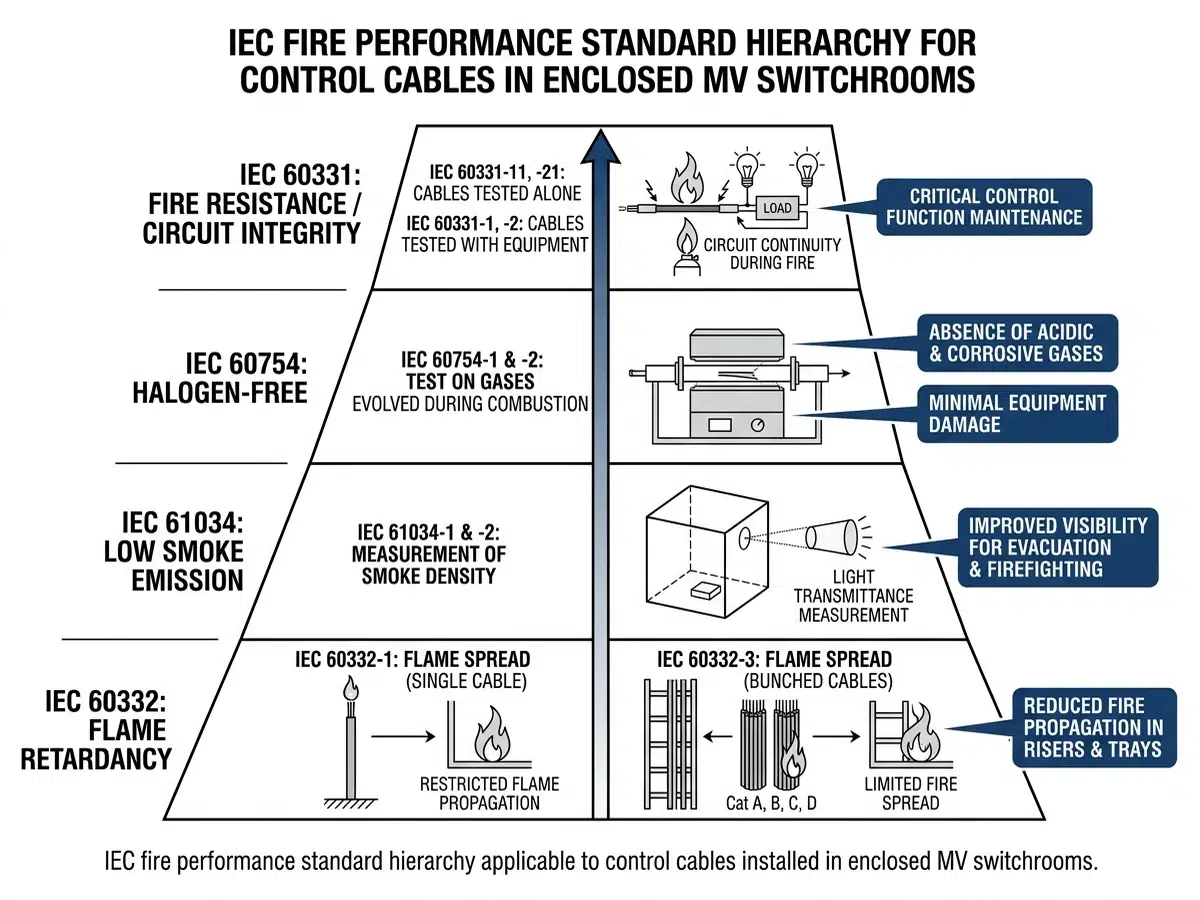
يشتمل أداء كابل التحكم في الحرائق على خصائص متعددة، يتم تقييم كل منها من خلال اختبارات معيارية محددة:
مقاومة انتشار اللهب تقيس سلسلة IEC 60332 (IEC 60332) ميل الكابل لانتشار الحريق على طول طوله. تختبر المواصفة IEC 60332-1 الكابلات الفردية في ظروف اللهب الصغيرة، بينما تقوم المواصفة IEC 60332-3 بتقييم الكابلات المجمعة التي تمثل كثافات تركيب واقعية. تحد الفئة A (أعلى أداء) من انتشار اللهب إلى أقل من 2.5 متر على عينة طولها 3.5 متر.
مقاومة الحرائق (IEC 60331) يحدد الحفاظ على سلامة الدائرة أثناء التعرض للحريق. تستمر الكابلات التي تجتاز هذا الاختبار في العمل بالجهد المقنن أثناء تعرضها للهب 750 درجة مئوية لفترات محددة - عادةً 90 أو 120 دقيقة لدوائر السلامة الحرجة.
كثافة الدخان (IEC 61034) تحدد مدى انخفاض الرؤية أثناء احتراق الكابلات. تحافظ الكابلات منخفضة الدخان على الحد الأدنى من نفاذية الضوء 60%، وهو أمر بالغ الأهمية لسلامة الإخلاء وعمليات رجال الإطفاء.
محتوى الهالوجين وانبعاث الغازات الحمضية (IEC 60754) تؤثر على كل من السلامة البشرية وتآكل المعدات. تنتج الكابلات منخفضة الدخان الخالية من الهالوجين (LSZH) نواتج احتراق غير قابلة للتآكل، مما يحمي المعدات الإلكترونية الحساسة من تلف الغازات الحمضية.
تتطلب بيئات التركيب المختلفة مستويات مختلفة من أداء الحرائق:
محطات الكهرباء الفرعية تتطلب عادةً كابلات مثبطة للهب تفي بالفئة C من المواصفة القياسية IEC 60332-3 كحد أدنى. قد تسمح نقاط الإنهاء الخارجية بالتركيبات القياسية المثبطة للهب نظراً للتهوية الطبيعية وتباعد المعدات.
المنشآت الصناعية يتم تحديد تركيبات LSZH بشكل متزايد لحماية معدات التحكم في العمليات وتمكين الإخلاء الآمن للعاملين. وغالباً ما تفرض المنشآت البتروكيماوية استخدام كابلات مقاومة للحريق لدوائر الإغلاق في حالات الطوارئ.
محطات توليد الطاقة تتطلب كابلات مقاومة للحريق (IEC 60331) لأنظمة تعثر المفاعلات، وأجهزة التحكم في مياه التغذية في حالات الطوارئ، والدوائر الأخرى المتعلقة بالسلامة وفقًا للمتطلبات التنظيمية النووية أو معايير المحطات الحرارية المكافئة.
المنشآت تحت الأرض (أنفاق الكابلات والطوابق السفلية) تتطلب تصنيفات انتشار اللهب من الفئة A وانبعاثات دخان منخفضة بسبب المساحات الضيقة والتهوية المحدودة.
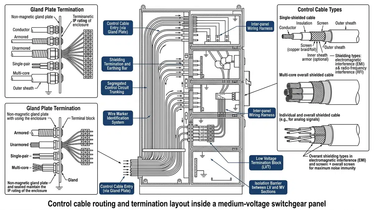
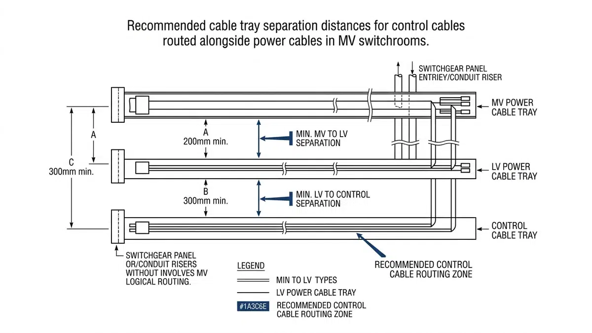
الفصل السليم للكابلات يمنع اقتران التداخلات ويحافظ على حواجز الحريق بين فئات الكابلات:
الفصل الجسدي بين كابلات الطاقة وكابلات التحكم باتباع قاعدة الـ 300 مم - مع الحفاظ على مسافة 300 مم كحد أدنى أو تركيب حواجز معدنية عندما يصبح من الضروري وجود مسافات أقرب. تزداد هذه المسافة بالتناسب مع مستويات الجهد فوق 15 كيلو فولت.
زوايا العبور بزاوية 90 درجة لتقليل الاقتران المغناطيسي عندما يجب أن تتقاطع كابلات التحكم مع موصلات الطاقة. تُنشئ التقاطعات المائلة مناطق اقتران ممدودة تزيد من الفولتية المستحثة بشكل كبير.
التوجيه الرأسي من خلال مقصورات الكابلات يتطلب الحفاظ على سلامة مانع الحريق عند اختراقات الأرضية والسقف. تعمل أنظمة النقل المصنعة مسبقًا والمزودة بتصنيفات مختبرة للحريق على تبسيط عملية التحقق من الامتثال.
بالنسبة للمسارات الأطول خارج نطاق مجموعة لوحات التوزيع الكهربائية، يجب توسيع نطاق خطة الفصل نفسها لتشمل نظام دعم الكابلات في المصنع؛ أ دليل تركيب حامل الكابلات يساعد على الحفاظ على اتساق مستوى ملء الصينية، والمسافات بينها، ونقاط منع انتقال الحريق، ونصف قطر الانحناء بعد خروج كابلات التحكم من لوحة MV.
توازن متطلبات أنصاف أقطار ثني كابل التحكم بين قيود الإجهاد الميكانيكي وقيود التركيب:
يؤدي تجاوز حدود نصف قطر الانحناء أثناء التركيب إلى حدوث تلف فوري أو كامن بما في ذلك استطالة الموصلات وتشوه الدرع وتشقق العزل. لقد تتبعت العديد من تحقيقات الأعطال المتقطعة إلى تلف التركيب عند الانحناءات الحادة، خاصةً داخل حاويات الألواح المحصورة.
داخل اللوحات MV، يجب أن تستوعب آليات دعم الكابلات داخل اللوحات MV التدوير الحراري والاهتزازات والوصول إلى الصيانة:
صواني الكابلات بنسب تعبئة مناسبة (40% كحد أقصى لكابلات الطاقة، و50% لكابلات التحكم) تتيح تبديد الحرارة الكافي وإضافات الكابلات المستقبلية. تسهل الصواني من نوع السلم إسقاط الكابلات الرأسية بشكل أفضل من البدائل ذات القاع الصلب.
مرابط الكابلات على مسافات مناسبة لمنع حركة الكابل أثناء أحداث الدائرة القصيرة. يجب أن تأخذ حسابات تباعد المرابط في الحسبان تيارات الأعطال المحتملة على الدوائر الثانوية للتصوير المقطعي المحوسب.
انتقالات القناة المرنة عند نقاط دخول اللوحة تستوعب تفاوتات الأبعاد وعمليات النقل الطفيفة للوحة. توفر الأنبوب المعدني المرن المحكم السوائل حماية بيئية مع السماح بإعادة توجيه الكابلات أثناء التعديلات.
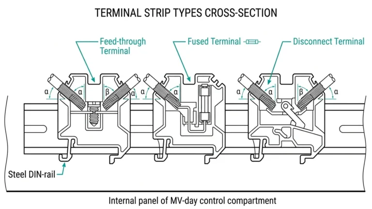
يؤثر اختيار الكتلة الطرفية بشكل كبير على موثوقية التوصيل على المدى الطويل:
أطراف طرفان محملان بنابض توفر ضغط تلامس ثابت بغض النظر عن تدوير درجة الحرارة والاهتزاز. ويؤدي التخلص من الصيانة الدورية لإعادة الضبط إلى زيادة تحديد المحطات الطرفية الزنبركية لدوائر الحماية الحرجة.
أطراف طرفان من النوع اللولبي تظل قياسية لأحجام الموصلات الكبيرة والتطبيقات التي تتطلب التحقق البصري من عزم الدوران. يتطلب التركيب السليم أدوات معايرة لعزم الدوران وعلامات مناسبة على الطرفية.
موصلات الإزاحة العازلة (IDC) تتيح الإنهاء السريع لكابلات الإشارة ذات المقاييس الصغيرة ولكنها تتطلب مطابقة دقيقة لمقاييس الموصلات. تناسب أطراف توصيل IDC تطبيقات الاتصالات والإشارات منخفضة المستوى حيث تبرر سرعة الإنهاء قيود المقياس.
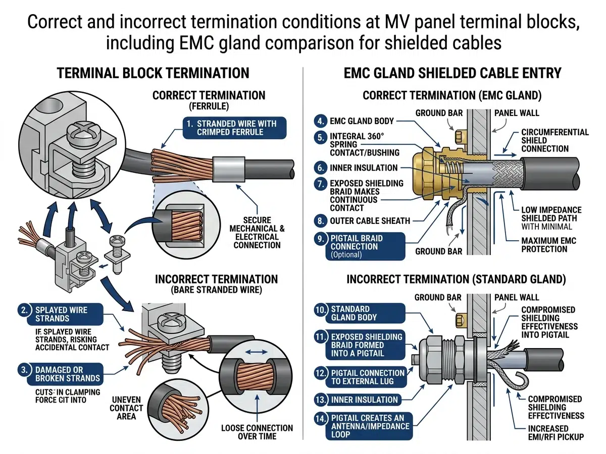
توفر النهايات المجعدة موثوقية فائقة مقارنةً بالطرف اللولبية عند تنفيذها بشكل صحيح:
معايرة أداة التجعيد يجب أن يتم التحقق كل ثلاثة أشهر أو حسب توصيات الشركة المصنعة. ينتج عن القوالب البالية تجعيدات رخوة قد تجتاز الفحص البصري بينما توفر ضغط تلامس غير كافٍ.
إعداد الموصلات يتضمن طول الشريط المناسب (تجنب الموصلات المكشوفة خارج البرميل)، وترتيب الخيوط (عدم وجود خيوط مقطوعة أو متقاطعة)، والنظافة (إزالة طبقات الأكسيد من الموصلات القديمة).
معايير فحص التجعيد تشمل الإغلاق السليم للقالب وموضع الموصل في المنتصف وبروز الموصل المرئي في طرف الماسورة. تتطلب العديد من المواصفات فحص 100% للتجعيد في دوائر الحماية الحرجة.
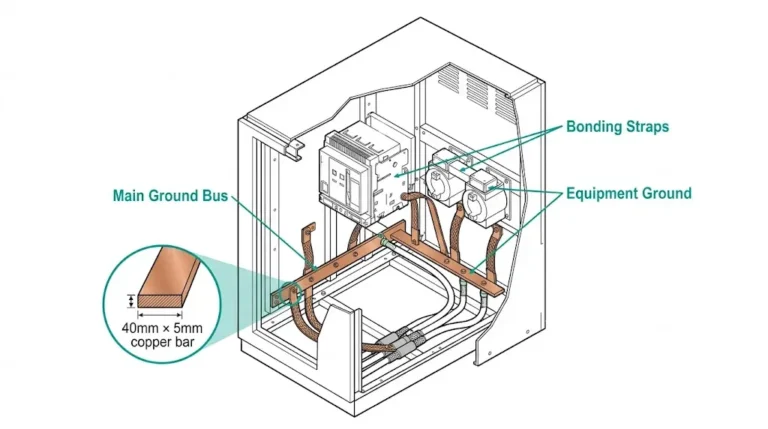
تؤثر جودة إنهاء الدرع بشكل مباشر على فعالية التدريع:
إنهاء بزاوية 360 درجة من خلال غدد الكابلات EMC توفر تلامس درع محيطي كامل، مما يحافظ على سلامة الدرع من خلال نقطة دخول اللوحة. توفر هذه الطريقة رفضًا للضوضاء أكبر بمقدار 40-60 ديسيبل من التوصيلات الضفيرة عند الترددات التي تزيد عن 10 ميجاهرتز.
وصلات الضفيرة (سلك تصريف الدرع المنتهي إلى ناقل أرضي) توفر البساطة ولكنها تخلق مقاومة استقرائية تقلل من فعالية التدريع عالي التردد. عندما لا يمكن تجنب أسلاك التوصيل المصنوعة من أسلاك التوصيل الضفيرة، حافظ على أطوال أقل من 50 مم ووجهها مباشرة إلى أقرب نقطة أرضية.
أنظمة حافلات الدرع الواقية دمج إنهاءات الدروع الفردية في سطح متساوي الجهد مشترك، مما يسهل التركيب مع الحفاظ على جودة الإنهاء المناسبة. تقدم العديد من الشركات المصنعة أنظمة إنهاء الدرع المعيارية المصممة خصيصًا لتطبيقات لوحة التحكم.
قبل التركيب، يجب أن تخضع كابلات التحكم:
اختبار مقاومة العزل عند 500 فولت تيار مستمر كحد أدنى، والتحقق من القراءات التي تتجاوز 100 متر مكعب لكل كيلومتر. تشير القراءات الأقل إلى دخول الرطوبة أو عيوب التصنيع التي تتطلب رفض الكابل.
التحقق من الاستمرارية يؤكد سلامة الموصلات ويحدد التوصيلات المتقاطعة قبل التركيب مما يجعل التصحيحات صعبة.
اختبار استمرارية الدرع عند مستويات تيار منخفضة تحدد انكسارات الدرع التي من شأنها أن تؤثر على أداء EMC.
بعد اكتمال الإنهاء:
إعادة اختبار مقاومة العزل يحدد أضرار التركيب الناتجة عن شد الشد أو الانحناءات الحادة أو الصدمات الميكانيكية أثناء أنشطة الإنشاء المتزامنة.
التحقق من نقطة إلى نقطة التأكد من الإنهاء الصحيح مقابل مخططات الأسلاك، وهو أمر ضروري قبل تنشيط دوائر الحماية والتحكم.
قياسات الجهد المستحث في ظل ظروف التحميل تحديد مستويات التداخل الفعلية في الدوائر الحساسة. إن القياسات التي تتجاوز 1% من مستويات الإشارة الاسمية تستدعي إجراء تحقيق وإمكانية إعادة التوجيه.
التحقق من فعالية الدرع باستخدام اختبار الحقن يؤكد أداء التدريع المناسب في التكوينات المثبتة.
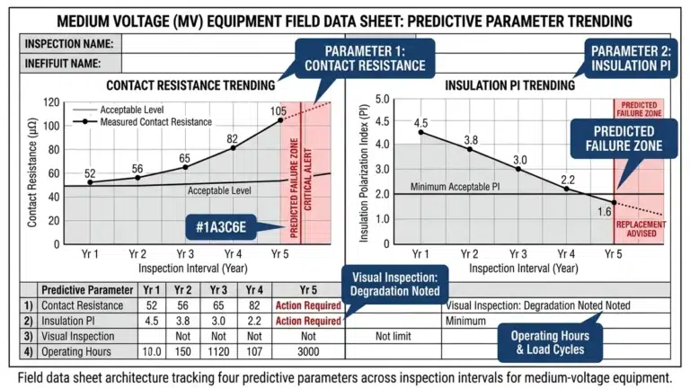
أثناء ترقية نظام التحكم مؤخرًا في مصفاة بساحل الخليج، أظهرت كابلات التحكم في مجموعة المفاتيح الكهربائية الحالية بجهد 13.8 كيلو فولت مشاكل تداخل مزمنة. وتعرضت الدوائر الثانوية للتصوير المقطعي المحوسب المقطعي المحوسب الموجهة بجوار كابلات طاقة محرك التردد المتغير لضوضاء مستحثة تتجاوز قدرات ترشيح مرحل الحماية، مما تسبب في حدوث أعطال مزعجة أثناء بدء تشغيل المحرك.
وقد تضمن الحل تركيب ثلاثيات محمية بشكل فردي مع تدريع مركب من رقائق/ضفيرة لجميع دوائر التصوير المقطعي المحوسب، وتنفيذ وصلات درع بزاوية 360 درجة في كلا الطرفين، وإعادة توجيه الكابلات لتحقيق فصل 450 مم كحد أدنى عن موصلات طاقة محرك الترددات المنخفضة. أكدت قياسات ما بعد التعديل انخفاض الضوضاء المستحثة من ذروة 850 مللي فولت إلى أقل من 15 مللي فولت - في حدود تحمل الترحيل.
حدد مشروع محطة نقل فرعية بجهد 230/34.5 كيلو فولت كابلات مقاومة للحريق لجميع دوائر الحماية بعد مخاوف من حوادث الحرائق في المرافق الإقليمية. تطلب التركيب:
يُظهر السجل التشغيلي لمدة 18 شهرًا عدم حدوث أي خلل في الحماية يعزى إلى مشكلات في كابل التحكم، مما يؤكد صحة نهج المواصفات المتحفظ.
تصبح الكابلات المحمية ضرورية عند توجيه دوائر التحكم في نطاق 300 مم من موصلات الطاقة، أو عند وجود إشارات تناظرية حساسة (أقل من 1 فولت أو مستويات ميكروأمبير)، أو عندما تتطلب بروتوكولات الاتصال أداءً محددًا للتوافق الكهرومغناطيسي EMC، أو عندما تتضمن بيئة التركيب محركات التردد المتغير أو أفران القوس أو غيرها من مصادر التداخل العالية. بالنسبة للتركيبات الجديدة ذات الجهد المتوسط، غالبًا ما يكون تحديد الكابلات المحمية عالميًا أكثر اقتصادًا من التطبيق الانتقائي، مع الأخذ في الاعتبار تكاليف استكشاف الأخطاء وإصلاحها للمشاكل المتعلقة بالضوضاء.
تستخدم كابلات LSZH (منخفضة الدخان الخالية من الهالوجين) عوازل وغلاف من البولي أوليفين الذي ينتج عنه الحد الأدنى من الدخان ولا ينتج عنه غازات حمضية أكالة أثناء الاحتراق. تطلق كابلات PVC القياسية غاز كلوريد الهيدروجين عند الاحتراق، والذي يشكل حمض الهيدروكلوريك في وجود الرطوبة، مما يؤدي إلى تآكل المعدات القريبة ويخلق مخاطر على الجهاز التنفسي. بينما تكلف كابلات LSZH عادةً 15-25% أكثر من مثيلاتها من PVC، فإن انخفاض أضرار التآكل على المعدات الإلكترونية وتحسين سلامة الإخلاء يبرر علاوة التكلفة في الأماكن المغلقة والمرافق ذات المعدات الحساسة.
نعم، مع اتخاذ الاحتياطات المناسبة. استخدم كابلات محمية بشكل فردي لدوائر التصوير المقطعي المحوسب لمنع اقتران المجال المغناطيسي بالموصلات المجاورة. تأكد من أن نسبة ملء القناة تسمح بمسافات كافية بين أنواع الكابلات. ضع في اعتبارك مستويات تيار العطل - يمكن أن تحمل الدوائر الثانوية للتصوير المقطعي المحوسب تي تي تي تي تي تيارات كبيرة أثناء أعطال نظام الطاقة، ويجب أن يأخذ تحديد حجم الموصل في الاعتبار التأثيرات الحرارية. بالنسبة لتطبيقات الحماية الحرجة، يوفر التوجيه المنفصل ضمانًا إضافيًا للموثوقية يستحق التكلفة الإضافية المتواضعة.
يعمل اتصال IEC 61850 GOOSE (حدث المحطة الفرعية الموجه للكائنات العامة) بسرعات إيثرنت التي تتطلب مناعة ضد الضوضاء عريضة النطاق. يوفر التأريض متعدد النقاط للدرع عند طرفي الكابل وعند أي نقاط تقاطع وسيطة حماية مثالية عالية التردد. استخدم كابلات التوصيل المحمية وحافظ على استمرارية الدرع من خلال المفاتيح ولوحات التوصيل. يجب أن يتصل الدرع بالنظام الأرضي الواقي عند كل نقطة إنهاء، مما يخلق مسارًا منخفض المقاومة للتيارات المستحثة.
يجب إعادة ضبط الوصلات الطرفية من النوع اللولبي أثناء التشغيل الأولي (بعد 24-48 ساعة من التشغيل للسماح بالاستقرار الحراري)، وفي أول فترة صيانة سنوية وبعد ذلك على فترات تتراوح بين 3 و5 سنوات حسب ظروف التشغيل. قد تتطلب الوصلات المعرضة للاهتزازات أو التدوير الحراري أو الأعطال ذات التيار العالي عناية أكثر تكرارًا. تستغني المحطات الطرفية المحملة بنابض عن متطلبات إعادة الربط تمامًا، مما يجعلها مفضلة بشكل متزايد للتطبيقات التي يكون فيها الوصول إلى الصيانة صعبًا أو مكلفًا.
تشتمل الوثائق الأساسية على جداول الكابلات التي تحدد كل كابل بمعرفات فريدة وألوان الموصلات ومواقع المحطات ومواصفات الكابلات. الاحتفاظ برسومات التوجيه حسب التركيب التي توضح مواضع التركيب الفعلية (وليس فقط نية التصميم). الاحتفاظ بسجلات الاختبار بما في ذلك قياسات مقاومة العزل ونتائج التحقق من الاستمرارية وأي اختبار لفعالية الدرع. احتفظ بأوراق بيانات الشركة المصنعة التي تؤكد تصنيفات الحريق والخصائص الكهربائية. تثبت هذه الوثائق أنها لا تقدر بثمن أثناء استكشاف الأخطاء وإصلاحها والتعديلات والتدقيق التنظيمي.
تتطلب الإنهاءات الخارجية اختيار غدة كابل مناسبة مع تصنيفات IP (حماية الدخول) المناسبة - الحد الأدنى IP66 للتركيبات الخارجية MV. ضع مانعات التسرب المناسبة عند نقاط دخول الكابلات باتباع تعليمات الشركة المصنعة. تأكد من أن العبوات الطرفية تحافظ على التصريف المناسب (فتحات التصفية عند النقاط المنخفضة) بدلاً من محاولة الإغلاق المحكم الذي يفشل حتمًا. ضع في اعتبارك عناصر التنفس التي تعادل الضغط مع منع دخول الرطوبة. بالنسبة للتطبيقات الحرجة، حدد كتل طرفية مملوءة بالهلام تستبعد الرطوبة من نقاط التوصيل.
يتطلب اختيار كابل التحكم في لوحات الجهد المتوسط الاهتمام بالعديد من العوامل المترابطة التي تحدد مجتمعةً موثوقية النظام وسلامته. يجب أن توجه المبادئ التالية قرارات المواصفات والتركيب:
يجب أن يتطابق اختيار التدريع مع البيئة الكهرومغناطيسية. فهم مصادر التداخل، وتقييم حساسية الإشارة، واختيار أنواع الدروع وطرق التأريض المناسبة. نادرًا ما يتسبب الإفراط في تحديد مواصفات التدريع في حدوث مشاكل؛ بينما يؤدي نقص المواصفات إلى كوابيس تشغيلية.
تختلف متطلبات أداء الحرائق حسب التطبيق والاختصاص القضائي. تقييم متطلبات انتشار اللهب ومقاومة الحرائق وانبعاثات الدخان والمحتوى الهالوجيني بناءً على موقع التركيب والقوانين المعمول بها وتحليل العواقب. تنسيق تصنيفات الحرائق مع الاستراتيجية الشاملة للحماية من الحرائق بما في ذلك أنظمة الكشف والإخماد.
يمنع انضباط التوجيه من حدوث مشاكل. الحفاظ على مسافات الفصل، ومراعاة حدود نصف قطر الانحناء، وتوفير الدعم الكافي. يمنع الجهد الإضافي المتواضع أثناء التركيب سنوات من استكشاف الأخطاء وإصلاحها وأعطال الحماية المحتملة.
تحدد جودة الإنهاء موثوقية الاتصال. حدد أنواع المحطات الطرفية المناسبة، ونفذ عمليات التجعيد بشكل صحيح، ونفذ وصلات إنهاء الدرع التي تحافظ على فعالية التدريع من خلال حدود اللوحة.
اختبار التحقق من صحة الأداء. اختبار ما قبل التركيب والتشغيل التجريبي يكتشف العيوب قبل أن تتسبب في مشاكل تشغيلية. توثيق النتائج للرجوع إليها وتحديد الاتجاهات المستقبلية.
وتمثل كابلات التحكم جزءًا صغيرًا من تكاليف مشروع لوحة الجهد المتوسط، ولكنها تؤثر بشكل كبير على النجاح التشغيلي. ويؤدي استثمار الاهتمام الهندسي المناسب وتحديد المواد عالية الجودة إلى تحقيق عوائد طوال عمر المعدات الذي يتراوح بين 30 و40 عاماً من الخدمة.