Need Full Specifications?
Download our 2025 Product Catalog for detailed drawings and technical parameters of all switchgear components.
Get CatalogDownload our 2025 Product Catalog for detailed drawings and technical parameters of all switchgear components.
Get CatalogDownload our 2025 Product Catalog for detailed drawings and technical parameters of all switchgear components.
Get Catalog
Select control cables for MV panels by shielding, fire rating, routing, termination, testing, and EMC requirements.
Control cables in medium voltage (MV) panels serve as the nervous system of electrical infrastructure, transmitting critical signals for protection, metering, monitoring, and automation functions. While power cables often receive primary attention during system design, control cable selection directly impacts system reliability, personnel safety, and operational continuity. A single control cable failure can render protection schemes ineffective, potentially leading to equipment damage or catastrophic failures.
Having spent over fifteen years commissioning and troubleshooting MV switchgear across industrial facilities, power plants, and utility substations, I’ve witnessed firsthand how improper control cable selection creates insidious problems that manifest months or years after installation. Electromagnetic interference causing nuisance relay trips, fire-damaged cables propagating flames between compartments, and poorly terminated connections creating intermittent faults—these issues share a common root: inadequate attention to control cable specifications during the design phase.
This comprehensive guide addresses the essential considerations for control cable selection in MV panels rated from 1kV to 52kV, covering shielding requirements, fire performance ratings, routing best practices, and termination techniques that ensure long-term system integrity.
| Circuit type | Recommended cable structure | Key SEO/specification takeaway |
|---|---|---|
| CT and VT secondary circuits | Stranded copper, overall braid shield, clearly identified cores | Prioritize burden accuracy, short-circuit withstand, and shield continuity. |
| Trip, close, and spring-charge circuits | 2.5 mm² stranded copper with robust insulation and ferrules | Size for coil inrush, voltage drop, and mechanical durability. |
| Analog signals and sensors | Individually shielded pairs or triads with low-noise routing | Separate from switching transients and ground shields intentionally. |
| Ethernet, RS-485, and IEC 61850 signals | Controlled-impedance communication cable with EMC termination | Maintain shield continuity through glands, patch panels, and switches. |
Control cables in MV panels carry various signal types, each demanding specific cable characteristics:
Low-level analog signals (4-20mA current loops, RTD circuits, thermocouple outputs) require superior noise immunity and stable conductor resistance. These circuits typically connect current transformers, voltage transformers, temperature sensors, and pressure transmitters to protection relays and SCADA systems.
Digital signals (relay contacts, auxiliary switches, position indicators) operate at higher voltage levels (24-125VDC or 110-240VAC) with greater noise tolerance. However, cable capacitance becomes critical for longer runs exceeding 100 meters, particularly with solid-state relay inputs.
Communication circuits (Ethernet, serial RS-485, IEC 61850 GOOSE messaging) demand controlled impedance characteristics and specific shielding configurations to maintain data integrity at transmission speeds reaching 100 Mbps or higher.
Conductor sizing for control cables extends beyond simple current-carrying capacity calculations. The primary considerations include:
MV switchgear presents a challenging electromagnetic environment. Primary interference sources include:
Conducted interference originates from power frequency harmonics, switching transients, and ground potential rise during fault conditions. Motor drives, power electronic converters, and capacitor bank switching generate high-frequency conducted noise that couples into control circuits through shared grounding paths.
Radiated interference emanates from bus bars carrying high currents, arc flash events, partial discharge activity, and nearby radio frequency sources. The magnetic fields surrounding bus conductors can induce voltages in control cable loops exceeding protection relay operating thresholds.
Electrostatic interference couples capacitively from high-voltage conductors to adjacent control cables, particularly problematic in gas-insulated switchgear (GIS) where control cables route near SF6-filled compartments.
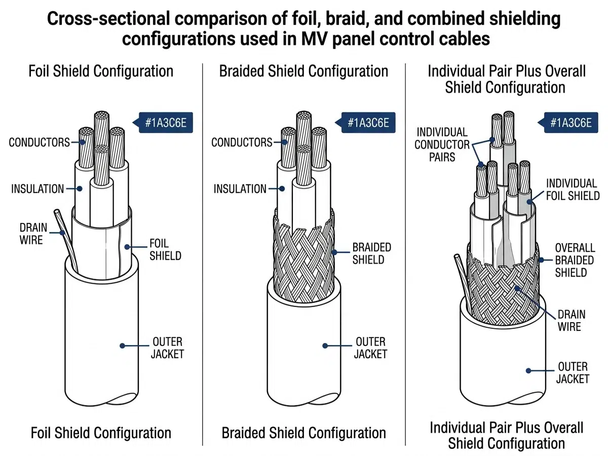
Foil shields (aluminum-polyester laminate) provide 100% coverage and excellent high-frequency attenuation above 1 MHz. The thin construction minimizes cable diameter but offers limited low-frequency magnetic field rejection. Foil shields work optimally for communication circuits and high-impedance analog inputs.
Braided shields (tinned copper braid, typically 85-95% coverage) deliver superior low-frequency magnetic shielding and better mechanical flexibility than foil alternatives. The lower transfer impedance at frequencies below 1 MHz makes braided shields preferred for CT/VT secondary circuits and critical protection signals.
Combination shields (foil plus braid) offer broadband protection across the frequency spectrum. Though more expensive, combination shielding proves essential for sensitive analog circuits in high-interference environments, such as partial discharge monitoring systems operating near MV buses.
Individually shielded pairs/triads prevent crosstalk between circuits within the same cable, crucial when mixing analog and digital signals. This construction allows multiple signal types to share a common cable route while maintaining signal integrity.
Shield grounding philosophy generates considerable debate among engineers. Based on extensive field measurements and industry standards (IEEE 1143, IEC 62271-1), I recommend the following approach:
Single-point grounding at the panel end prevents circulating currents through shield conductors, ideal for low-frequency analog circuits where induced currents would create measurement errors. This technique requires proper insulation of the shield at the remote end.
Multi-point grounding provides superior high-frequency noise rejection by creating a low-impedance path to ground at multiple locations. This approach suits digital communication circuits and installations where lightning-induced transients present concerns.
Hybrid grounding connects shields directly at the panel end and through high-frequency bypass capacitors (typically 10-100nF) at remote ends. This configuration prevents low-frequency circulating currents while maintaining high-frequency shielding effectiveness.
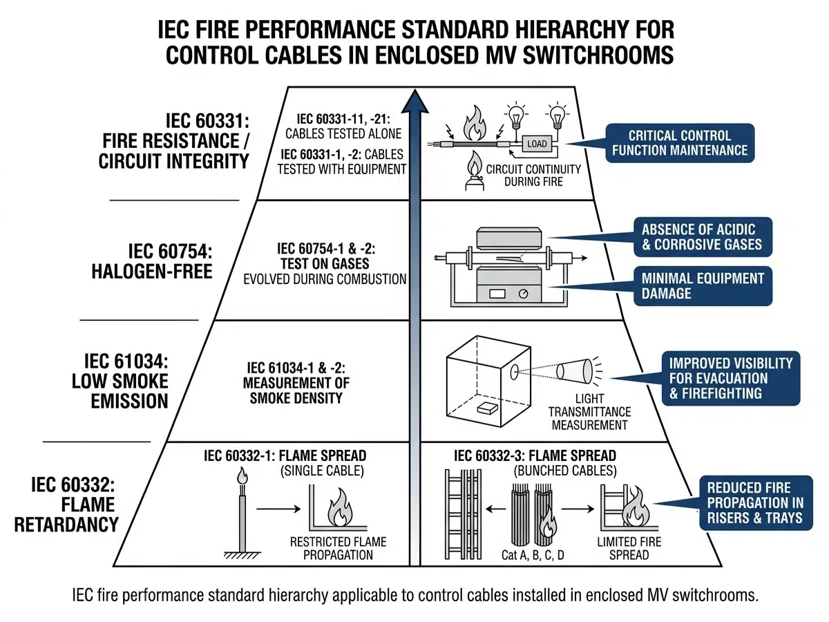
Control cable fire performance encompasses multiple characteristics, each evaluated through specific standardized tests:
Flame propagation resistance (IEC 60332 series) measures a cable’s tendency to spread fire along its length. IEC 60332-1 tests individual cables under small flame conditions, while IEC 60332-3 evaluates bunched cables representing realistic installation densities. Category A (highest performance) limits flame propagation to less than 2.5 meters on a 3.5-meter sample.
Fire resistance (IEC 60331) determines circuit integrity maintenance during fire exposure. Cables passing this test continue functioning at rated voltage while exposed to 750°C flames for specified durations—typically 90 or 120 minutes for critical safety circuits.
Smoke density (IEC 61034) quantifies visibility reduction during cable combustion. Low smoke cables maintain minimum 60% light transmittance, crucial for evacuation safety and firefighter operations.
Halogen content and acid gas emission (IEC 60754) affect both human safety and equipment corrosion. Low smoke zero halogen (LSZH) cables produce non-corrosive combustion products, protecting sensitive electronic equipment from acid gas damage.
Different installation environments demand varying fire performance levels:
Utility substations typically require flame-retardant cables meeting IEC 60332-3 Category C minimum. Outdoor termination points may permit standard flame-retardant constructions given natural ventilation and equipment spacing.
Industrial facilities increasingly specify LSZH constructions to protect process control equipment and enable safe personnel evacuation. Petrochemical installations often mandate fire-resistant cables for emergency shutdown circuits.
Power generating stations require fire-resistant cables (IEC 60331) for reactor trip systems, emergency feedwater controls, and other safety-related circuits per nuclear regulatory requirements or equivalent thermal plant standards.
Underground installations (cable tunnels, basements) demand Category A flame propagation ratings and low smoke emissions due to confined spaces and limited ventilation.
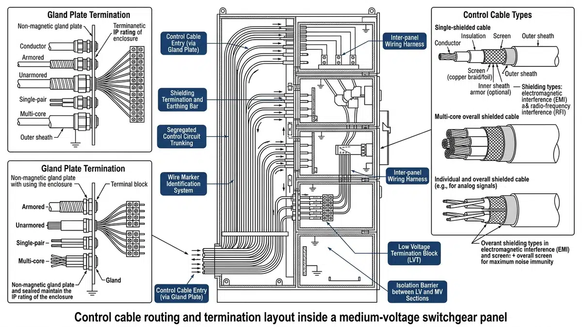
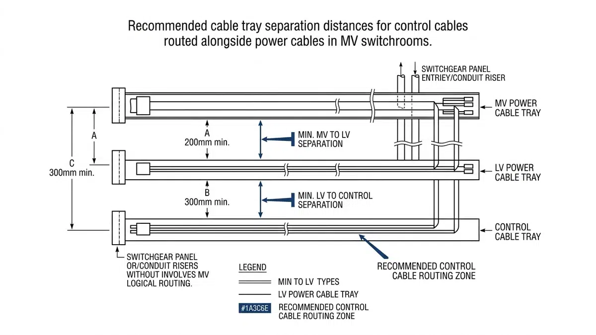
Proper cable segregation prevents interference coupling and maintains fire barriers between cable categories:
Physical separation between power and control cables follows the 300mm rule—maintaining minimum 300mm spacing or installing metallic barriers when closer spacing becomes necessary. This distance increases proportionally with voltage levels above 15kV.
Crossing angles of 90 degrees minimize magnetic coupling when control cables must cross power conductors. Oblique crossings create elongated coupling zones that significantly increase induced voltages.
Vertical routing through cable compartments requires maintaining fire-stop integrity at floor and ceiling penetrations. Pre-manufactured transit systems with tested fire ratings simplify compliance verification.
For longer routes outside the switchgear lineup, extend the same segregation plan into the plant cable support system; a cable tray installation guide helps keep tray fill, spacing, fire-stop points, and bend radius consistent after the control cables leave the MV panel.
Control cable bend radii requirements balance mechanical stress limitations against installation constraints:
Exceeding bend radius limits during installation creates immediate or latent damage including conductor elongation, shield deformation, and insulation cracking. I’ve traced multiple intermittent fault investigations to installation damage at sharp bends, particularly inside confined panel enclosures.
Within MV panels, cable support mechanisms must accommodate thermal cycling, vibration, and maintenance access:
Cable trays with proper fill ratios (40% maximum for power cables, 50% for control cables) enable adequate heat dissipation and future cable additions. Ladder-type trays facilitate vertical cable drops better than solid-bottom alternatives.
Cable cleats at appropriate intervals prevent cable movement during short-circuit events. Cleat spacing calculations should account for prospective fault currents on CT secondary circuits.
Flexible conduit transitions at panel entry points accommodate dimensional tolerances and minor panel relocations. Liquidtight flexible metallic conduit provides environmental protection while permitting cable rerouting during modifications.
Terminal block selection significantly impacts long-term connection reliability:
Spring-loaded terminals provide consistent contact pressure regardless of temperature cycling and vibration. The elimination of periodic retorquing maintenance makes spring terminals increasingly specified for critical protection circuits.
Screw-type terminals remain standard for larger conductor sizes and applications requiring visual torque verification. Proper installation requires calibrated torque tools and appropriate terminal markings.
Insulation displacement connectors (IDC) enable rapid termination of small-gauge signal cables but require precise conductor gauge matching. IDC terminals suit communication and low-level signal applications where termination speed justifies the gauge limitations.
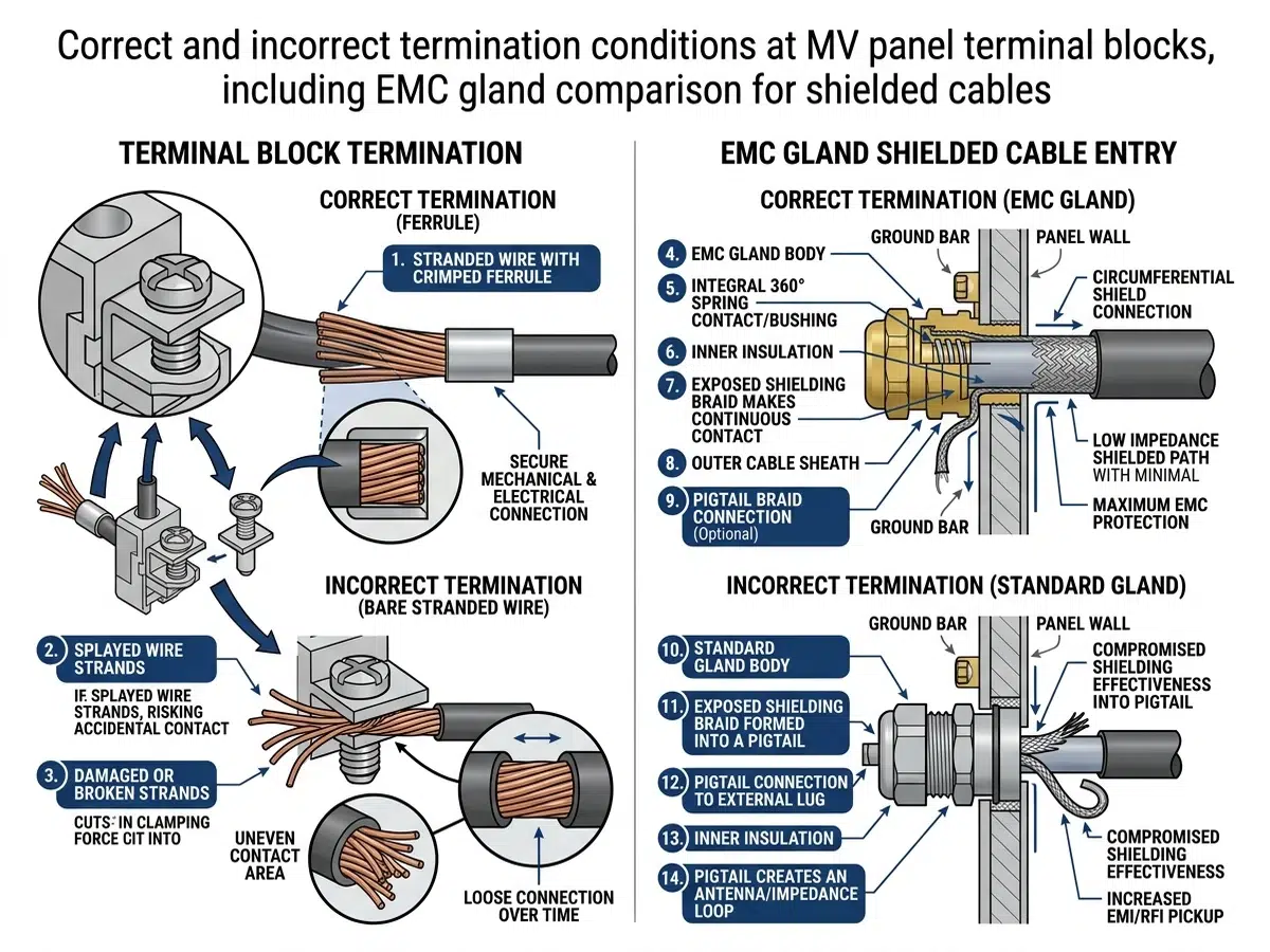
Crimped terminations offer superior reliability compared to screw terminals when properly executed:
Crimp tool calibration verification should occur quarterly or per manufacturer recommendations. Worn dies produce loose crimps that may pass visual inspection while providing inadequate contact pressure.
Conductor preparation includes proper strip length (avoiding exposed conductor beyond the barrel), strand arrangement (no cut or crossed strands), and cleanliness (removing oxide layers on aged conductors).
Crimp inspection criteria encompass proper die closure, centered conductor position, and visible conductor protrusion at the barrel end. Many specifications require 100% inspection of crimps on critical protection circuits.
Shield termination quality directly affects shielding effectiveness:
360-degree termination through EMC cable glands provides complete circumferential shield contact, maintaining shield integrity through the panel entry point. This method delivers 40-60 dB greater noise rejection than pigtail connections at frequencies above 10 MHz.
Pigtail connections (shield drain wire terminated to ground bus) offer simplicity but create an inductive impedance that degrades high-frequency shielding effectiveness. When pigtails are unavoidable, keep lengths under 50mm and route directly to the nearest ground point.
Shield bus systems consolidate individual shield terminations into a common equipotential surface, simplifying installation while maintaining proper termination quality. Several manufacturers offer modular shield termination systems designed specifically for control panel applications.
Before installation, control cables should undergo:
Insulation resistance testing at 500VDC minimum, verifying readings exceed 100 MΩ per kilometer. Lower readings indicate moisture ingress or manufacturing defects requiring cable rejection.
Continuity verification confirms conductor integrity and identifies crossed connections before installation makes corrections difficult.
Shield continuity testing at low current levels identifies shield breaks that would compromise EMC performance.
After termination completion:
Insulation resistance re-testing identifies installation damage from pulling tension, sharp bends, or mechanical impacts during concurrent construction activities.
Point-to-point verification confirms correct termination against wiring diagrams, essential before energizing protection and control circuits.
Induced voltage measurements under load conditions quantify actual interference levels in sensitive circuits. Measurements exceeding 1% of nominal signal levels warrant investigation and potential re-routing.
Shield effectiveness verification using injection testing confirms adequate shielding performance in installed configurations.
During a recent control system upgrade at a Gulf Coast refinery, the existing 13.8kV switchgear control cables exhibited chronic interference problems. CT secondary circuits routed adjacent to variable frequency drive power cables experienced induced noise exceeding protection relay filtering capabilities, causing nuisance trips during motor starting.
The solution involved installing individually shielded triads with combination foil/braid shielding for all CT circuits, implementing 360-degree shield terminations at both ends, and rerouting cables to achieve minimum 450mm separation from VFD power conductors. Post-modification measurements confirmed induced noise reduction from 850mV peak to under 15mV—well within relay tolerance.
A 230/34.5kV transmission substation project specified fire-resistant cables for all protection circuits following regional utility fire incident concerns. The installation required:
The 18-month operational record shows zero protection misoperations attributable to control cable issues, validating the conservative specification approach.
Shielded cables become necessary when control circuits route within 300mm of power conductors, when sensitive analog signals (less than 1V or microampere levels) are present, when communication protocols require specific EMC performance, or when the installation environment includes variable frequency drives, arc furnaces, or other high-interference sources. For new MV installations, specifying shielded cables universally often proves more economical than selective application, considering the troubleshooting costs of noise-related problems.
LSZH (Low Smoke Zero Halogen) cables use polyolefin-based insulation and jacketing that produces minimal smoke and no corrosive acid gases during combustion. Standard PVC cables release hydrogen chloride gas when burning, which forms hydrochloric acid in the presence of moisture, corroding nearby equipment and creating respiratory hazards. While LSZH cables typically cost 15-25% more than PVC equivalents, the reduced corrosion damage to electronic equipment and improved evacuation safety justify the premium in enclosed spaces and facilities with sensitive equipment.
Yes, with proper precautions. Use individually shielded cables for CT circuits to prevent magnetic field coupling to adjacent conductors. Ensure the conduit fill ratio allows adequate spacing between cable types. Consider the fault current levels—CT secondary circuits can carry significant currents during power system faults, and conductor sizing must account for thermal effects. For critical protection applications, separate routing provides additional reliability assurance worth the modest additional cost.
IEC 61850 GOOSE (Generic Object Oriented Substation Event) communication operates at Ethernet speeds requiring broadband noise immunity. Multi-point shield grounding at both cable ends and at any intermediate junction points provides optimal high-frequency shielding. Use shielded patch cables and maintain shield continuity through switches and patch panels. The shield should connect to the protective earth system at each termination point, creating a low-impedance path for induced currents.
Screw-type terminal connections should be retorqued during initial commissioning (after 24-48 hours of operation to allow thermal settling), at the first annual maintenance interval, and subsequently at 3-5 year intervals depending on operational conditions. Connections subjected to vibration, thermal cycling, or high-current faults may require more frequent attention. Spring-loaded terminals eliminate retorquing requirements entirely, making them increasingly preferred for applications where maintenance access is difficult or costly.
Essential documentation includes cable schedules identifying each cable with unique identifiers, conductor colors, terminal locations, and cable specifications. Maintain as-built routing drawings showing actual installed positions (not just design intent). Preserve test records including insulation resistance measurements, continuity verification results, and any shield effectiveness testing. Keep manufacturer data sheets confirming fire ratings and electrical characteristics. This documentation proves invaluable during troubleshooting, modifications, and regulatory audits.
Outdoor terminations require proper cable gland selection with appropriate IP (Ingress Protection) ratings—minimum IP66 for outdoor MV installations. Apply appropriate sealants at cable entry points following manufacturer instructions. Ensure terminal enclosures maintain proper drainage (weep holes at low points) rather than attempting hermetic sealing, which inevitably fails. Consider breathing elements that equalize pressure while preventing moisture entry. For critical applications, specify gel-filled terminal blocks that exclude moisture from connection points.
Control cable selection in MV panels demands attention to multiple interdependent factors that collectively determine system reliability and safety. The following principles should guide specification and installation decisions:
Shielding selection must match the electromagnetic environment. Understand interference sources, evaluate signal sensitivity, and select appropriate shield types and grounding methods. Over-specifying shielding rarely causes problems; under-specifying creates operational nightmares.
Fire performance requirements vary by application and jurisdiction. Evaluate flame propagation, fire resistance, smoke emission, and halogen content requirements based on installation location, applicable codes, and consequence analysis. Coordinate fire ratings with overall fire protection strategy including detection and suppression systems.
Routing discipline prevents problems. Maintain segregation distances, observe bend radius limits, and provide adequate support. The modest additional effort during installation prevents years of troubleshooting and potential protection failures.
Termination quality determines connection reliability. Select appropriate terminal types, execute crimps properly, and implement shield terminations that preserve shielding effectiveness through the panel boundary.
Testing validates performance. Pre-installation and commissioning testing catches defects before they cause operational problems. Document results for future reference and trending.
Control cables represent a small fraction of MV panel project costs but significantly influence operational success. Investing appropriate engineering attention and specifying quality materials yields returns throughout the equipment’s 30-40 year service life.