هل تحتاج إلى المواصفات الكاملة؟
قم بتنزيل كتالوج منتجاتنا لعام 2025 للحصول على رسومات تفصيلية ومعايير تقنية لجميع مكونات المفاتيح الكهربائية.
احصل على الكتالوج
قم بتنزيل كتالوج منتجاتنا لعام 2025 للحصول على رسومات تفصيلية ومعايير تقنية لجميع مكونات المفاتيح الكهربائية.
احصل على الكتالوج قم بتنزيل كتالوج منتجاتنا لعام 2025 للحصول على رسومات تفصيلية ومعايير تقنية لجميع مكونات المفاتيح الكهربائية.
احصل على الكتالوج
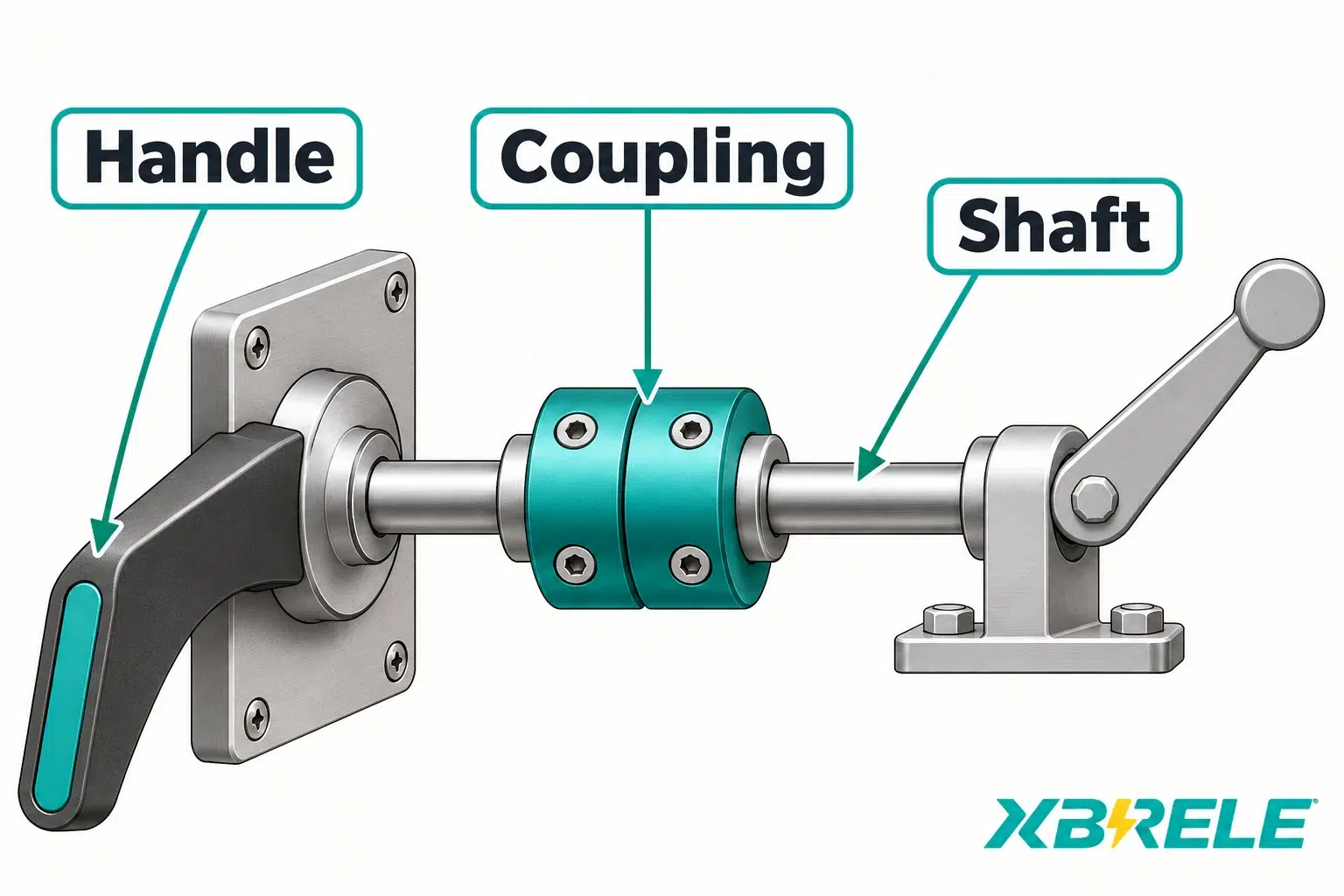
Review MV earthing-switch shaft direction, coupling and linkage geometry, interlock feedback and mounting interfaces before approving an installation or replacement.
An earthing switch may fit the panel’s mounting holes yet fail to reach the intended position because the drive direction, linkage geometry or feedback cam does not match the installed arrangement. Simply specifying voltage, phase spacing and a compatible model prefix does not guarantee that the drive shaft direction, linkage travel, actual blade positions, interlock logic and primary earth path will align with the panel design. This article helps OEM engineers review the complete mechanical-drive chain, establish unambiguous viewpoint conventions, verify linkage geometry through the full stroke, map interlocks to actual positions, separate mounting from earthing paths, and assemble a drawing-review handover that prevents installation holds.
In the EK6-type arrangement discussed here, fixed contacts, moving blades and a short-circuiting bridge form part of the designed primary earth path. Other constructions must be read from their own assembly drawings. Yet the mechanical drive chain includes several separate interfaces: the drive shaft that rotates within the switch bearing brackets, the coupling or gearbox that connects the shaft to the front-panel actuator, the front handle or motor operator that provides input, and the auxiliary contacts plus mechanical indicators that report position. Each interface has independent mechanical requirements. The drive chain transmits torque and motion; in this arrangement, the primary earth path carries its assigned electrical duty through the blades, bridge and specified flexible braided conductors to the ground bus. These two functions must not be confused.
ABB’s EK6 instructions, section 3, describe a particular design in which driver levers and toggle springs transmit mechanical force and bearing brackets require torsionally rigid mounting, while the earthing blades are electrically connected through stranded copper conductors to earth—a distinct path from the mechanical drive. A manual-operation panel and a motor-driven panel may use the same active switch contacts but specify different shaft orientation, coupling geometry, lever pivot location and feedback cam index because the drive side and actuator differ. Voltage rating, phase spacing and catalogue model alone do not define these interfaces.
This review addresses installation-interface design, not switching theory or operating procedures. For that scope you already require the manufacturer’s dimensional drawings, shaft connection details, linkage geometry, interlock truth table and primary earth-path connection diagram before releasing an order or accepting delivery.
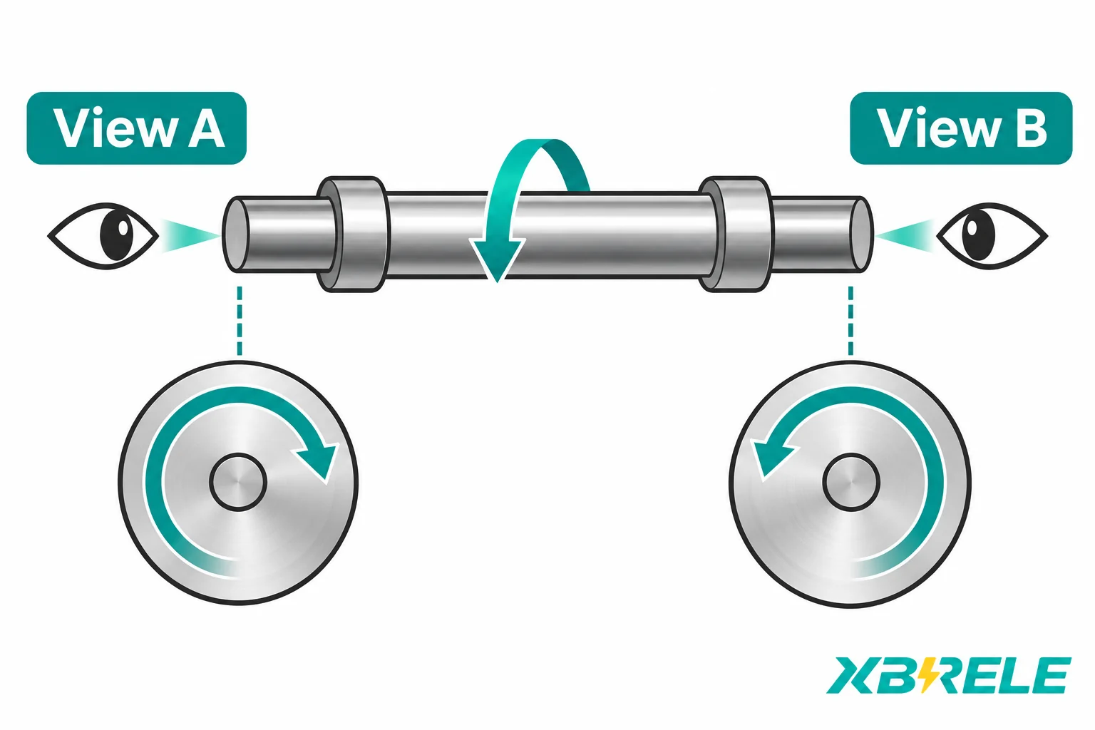
Describing the switch as “clockwise to close” is meaningless without specifying from which shaft end you are looking and the reference open or closed state. The same physical rotation viewed from the opposite shaft end appears to rotate in the opposite direction. If the front handle on the panel door rotates clockwise to close when viewed from the operator position, that rotation is transmitted through a coupling or bevel gearbox to the output shaft on the active switch. Record the input and output rotation separately from their named viewing ends. Gears and linkages can change the relationship between them; comparing clockwise labels on different shaft axes without those viewpoints is ambiguous. There is no universal closing direction or angular position.
Each interface must therefore record:
For example, two otherwise similar panels might use the same active-switch design but install the motor operator on opposite sides of the panel. One panel’s motor drives the shaft from the left end; the other drives from the right end. If both operators are ordered “clockwise to close” without a stated viewing end, the instruction may be interpreted as opposite physical rotations in the two installations. An engineering hold and manufacturer disposition are then required to resolve the mismatch before energization. Specifying direction always requires a named shaft end, a reference state and the rotation sense observed from that end.
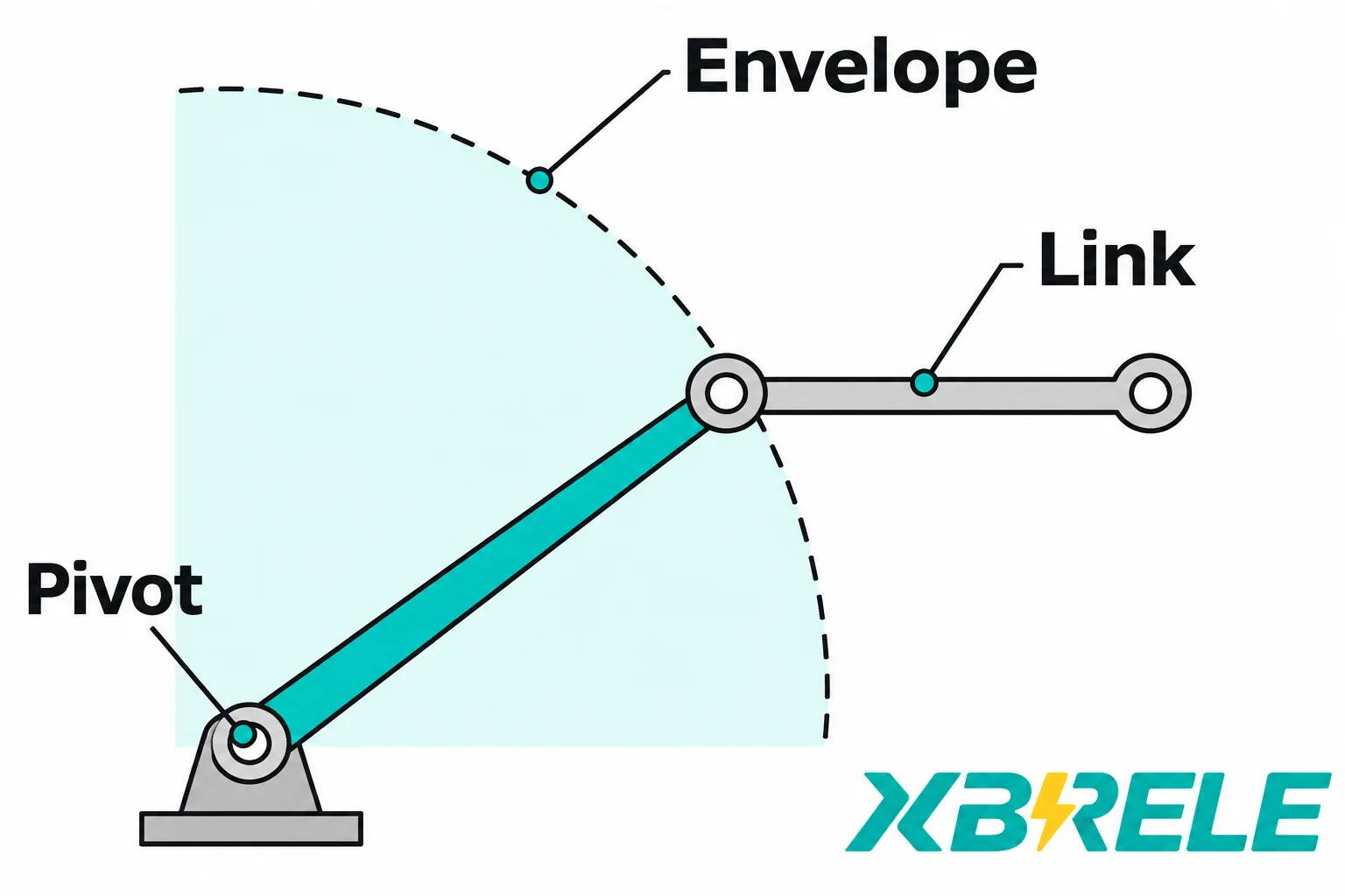
The linkage connecting the front actuator to the active switch comprises levers, connecting rods and pivots. Lever radius, connecting-rod length and pivot location determine the torque multiplication, stroke and potential dead-center conditions. Changing the lever hole changes the effective moment arm and the rod displacement for a given shaft rotation. Rod force and transmitted torque depend on the perpendicular lever arm, which varies through the motion. If the linkage approaches a straight-line configuration at either end of travel, small input motions produce little output and the mechanism may jam or require excessive force.
Backlash and compliance in the linkage allow the input to move before the blade responds. In a snap-action closing mechanism—such as the toggle-spring arrangement described in ABB EK6 documentation—the input drive rotation is not linearly related to contact angle throughout the stroke. The spring stores energy during the initial handle travel and releases it rapidly to snap the blade into the closed position. Opening behavior differs and may require sustained force. This means the input shaft angle is not a direct indicator of blade position during the stroke.
Verifying the linkage requires:
No universal torque value or connecting-rod length applies to all installations. Do not cut, redrill pivot holes or reindex levers based on assumed values. Use the manufacturer’s dimensional drawing and linkage geometry to confirm that the handle stroke matches the required blade travel and that the mechanism reaches the drawn fully closed position without obstruction.
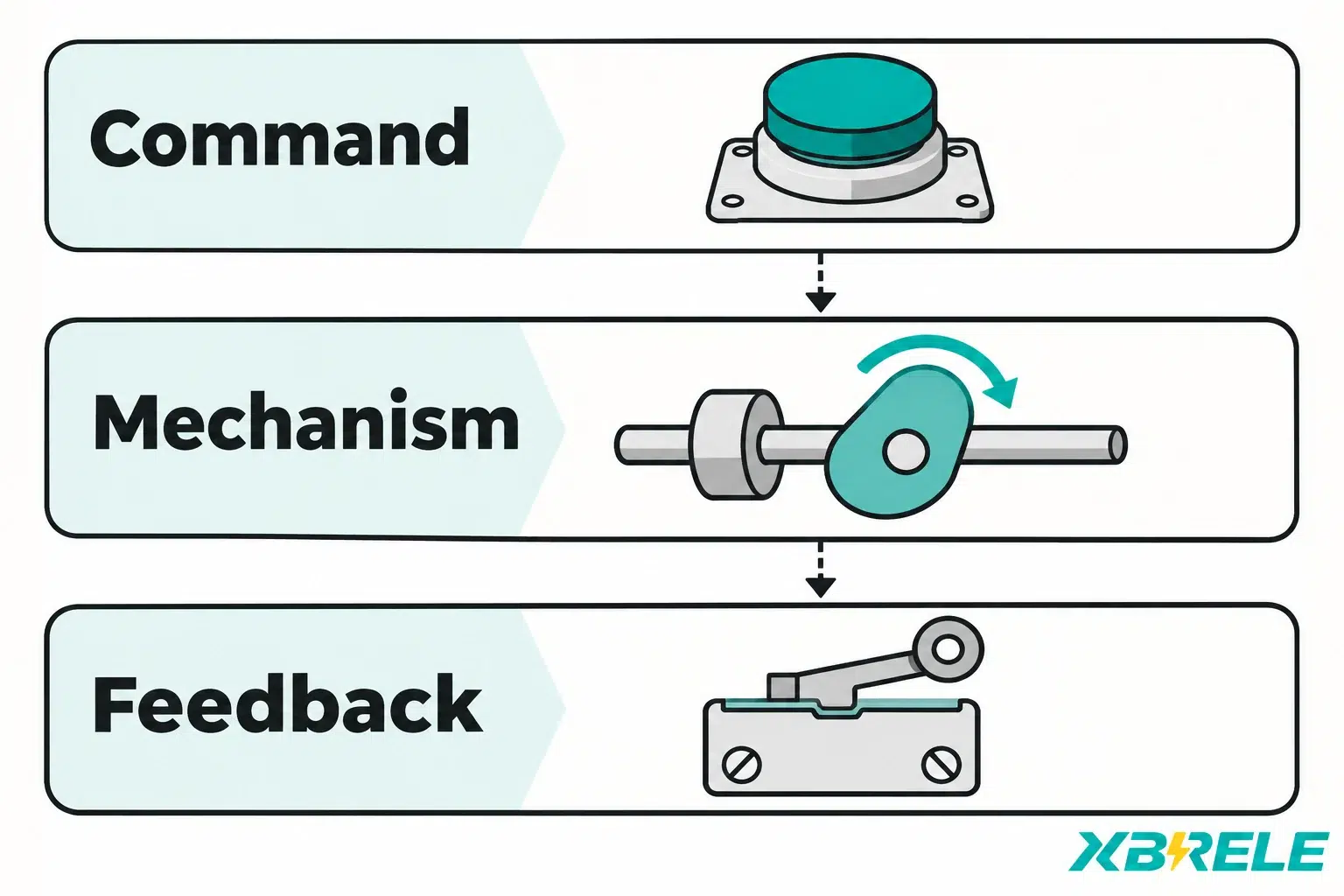
Actual blade position, mechanical position indication and auxiliary contact state are three separate sources of evidence. A drive command—whether from a front handle or a motor controller—is not proof that the blade has moved. Motor status—running, stopped or fault—is not proof of blade position. Interlock logic and annunciation must map to the actual state of the earthing switch.
IEC 62271-102:2018+AMD1:2022 CSV, the standard covering AC disconnectors and earthing switches for rated voltages above 1 000 V and service frequencies up to 60 Hz, is identified in the official revision summary as including position-indication/signalling requirements and mechanical-interlocking tests. The standard establishes that indication and interlocking are part of the functional design, not incidental. The installed panel’s matrix must prevent conflicting energization and unsafe access or movement according to its approved design. Validate each permitted and blocked action against actual positions and all required conditions; neither a universal auxiliary-contact assignment nor a dark voltage-presence lamp establishes permission.
Cam actuation and lost motion must be verified:
The following table summarizes the position-evidence requirements and fault cases:
| المنصب | Required evidence | Interlock response | Fault case |
|---|---|---|---|
| OPEN confirmed | Actual active-switch open position verified by the approved inspection, with the specified indications consistent | Apply the approved matrix and all other permissive conditions | Blade stuck partially open; feedback lost |
| CLOSED confirmed | Required contact engagement verified by the approved inspection, with the specified indications consistent | Prevent conflicting energization; apply the panel’s defined movement/access rules | Blade not fully engaged; feedback lost |
| متوسط | Actual active-switch position observed between its defined end positions | Block all conflicting operations until resolved | Handle forced; motor stalled; cam loose |
| غير معروف | Position unconfirmed: missing signal, disagreeing indications, or command without verified position | Inhibit unsafe requests; preserve required protective actions | Auxiliary-contact wiring fault; power loss |
Do not perform energized testing or bypass interlocks to “prove” position. Position confirmation during commissioning must use the manufacturer’s approved inspection procedure under outage conditions with qualified personnel. No live switching steps are part of installation acceptance.
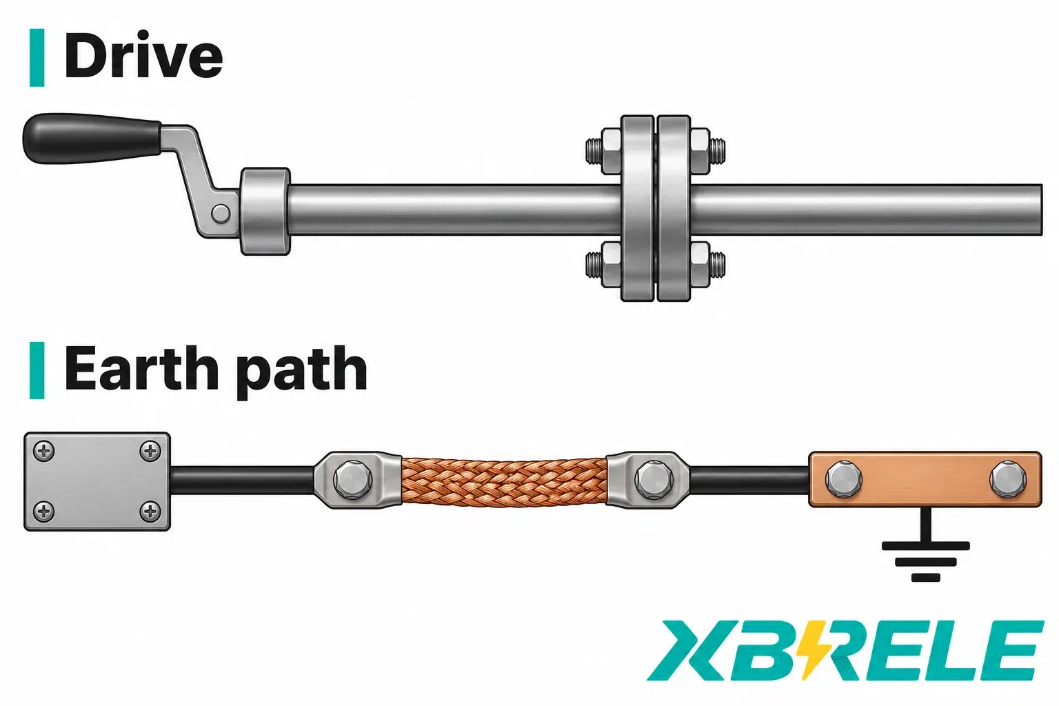
Mechanical mounting and the primary earth path are independent interfaces that must both be reviewed before installation release.
Mounting and alignment: Bearing brackets require rigid, flat mounting surfaces and accurate positioning so that the fixed contacts align with the moving blades per the dimensional drawing. Support insulation and phase-to-phase clearance are verified separately. Any misalignment in the mounting plane will force the blade to twist or bind during operation, increasing mechanical wear and potentially preventing full contact closure. The mounting-hole pattern, datum surfaces and torque specifications come from the manufacturer’s installation manual, not generic switchgear assembly instructions.
Primary earth path: In the described EK6-type arrangement, the earthing blades connect through a short-circuiting bridge and specified flexible braided conductors to the ground bus; the actual primary-path drawing governs the construction and connections for each assembly. This path is distinct from the mechanical drive. The drive coupling, shaft bearing and linkage rods are mechanical load-carrying elements; they must not be assumed to form a reliable fault-current path. The actual primary earth-path drawing shows the blade-to-bridge connection, the flexible braid attachment points (which allow blade movement without fatiguing the conductor), the ground-bus connection and the specified conductor construction and dimensions forming part of the verified short-circuit path. Verifying this path requires inspecting the braid attachment torque, confirming the braid route does not clash with moving parts, and checking the ground-bus connection integrity.
Making rating versus installation quality: A higher declared short-circuit making rating cannot compensate for misaligned contacts, inadequate mounting rigidity, or an incorrectly indexed interlock. The making rating is a type-test result that assumes correct installation per the manufacturer’s specification. If installation deviates—linkage adjusted to force closure, contacts not fully engaged, or a required earth connection omitted—the applicability of the declared performance is no longer established. No installation test-current threshold replaces the drawing review and mechanical inspection.
Before ordering or accepting an earthing-switch installation, compile the following information in a structured handover document or request-for-quotation table. This record ensures that all mechanical, electrical and interlock interfaces have been addressed and that the manufacturer’s dimensional drawing, the panel layout, the drive-side orientation and the interlock logic agree.
| Interface category | Required information |
|---|---|
| Model and drawing revision | Manufacturer, model designation (e.g., JN15, EK6, JN22), voltage rating, phase spacing, drawing revision number |
| Panel and drive side | Front/rear/left/right relative to lineup; drive-end shaft orientation; operator type (manual handle, manual/electrical, motor only) |
| Shaft direction and index | Viewpoint (named shaft end), rotation sense (CW/CCW from that viewpoint), open index angle, closed index angle, reference zero |
| Shaft connection | Diameter, keyway or spline profile, engagement length, axial retention method (e.g., retaining ring, set screw), coupling type |
| Linkage geometry | Lever radius and pivot location, connecting-rod length, swept envelope clearance, mechanical end stops, confirmed full-contact position |
| Mounting and fixed contacts | Mounting-hole pattern, datum surfaces, support-insulator type, fixed-contact location per dimensional drawing |
| Interlock matrix | Truth table mapping actual blade position (OPEN/CLOSED/intermediate/unknown) to interlock outputs; auxiliary-contact assignment |
| Position feedback | Mechanical indicator and auxiliary-contact cam actuation point, lost motion, supply voltage, normally-open or normally-closed logic |
| Primary earth path | Specified primary earth connections, flexible-braid routing and attachment where used, ground-bus termination, conductor construction, torque specification |
| Inspection and functional check | Manufacturer’s approved procedure for confirming full-contact engagement, interlock operation and earth-path continuity under outage |
Conditional failure cases: Consider two scenarios that illustrate the need for complete interface review:
Actuator fits but wrong closing direction: The motor operator mounts to the coupling and the shaft engages correctly. However, the motor was specified “clockwise to close” from the motor shaft end, while the panel drawing required “counterclockwise to close” from the same viewpoint. The motor runs, the coupling rotates, but the blade opens when the operator expects closure. This mismatch is not caught by a voltage rating or mounting-dimension check. Resolution requires the manufacturer’s approved disposition for the complete operator, limit, indication and interlock arrangement; a direction change cannot be treated as an isolated wiring alteration. An engineering hold is issued until the manufacturer provides a disposition and, if necessary, a replacement unit.
Motor limit made before blade engagement: The motor-operator travel limit switch is factory-set to stop the motor at a certain number of shaft rotations. However, the linkage in this installation has more backlash than the factory’s reference assembly, or the installer adjusted the linkage length slightly. As a result, the motor reaches its limit and stops قبل the blade achieves full contact with the fixed contact. The mechanical indicator shows CLOSED, but the contact pressure is insufficient and the short-circuit withstand is compromised. If the approved functional inspection finds a final-position mismatch, place the installation on hold. The manufacturer’s disposition must address the linkage, travel limits and feedback together, followed by the required verification under outage conditions with qualified personnel.
Both cases demonstrate that voltage rating, phase spacing and mounting-hole alignment are necessary but not sufficient. The complete installation interface—drive direction, linkage travel, actual blade position, interlock feedback and primary earth path—must be reviewed as an integrated system before the installation is released for energization.
For inquiries regarding earthing-switch families, mounting dimensions and drive-side configurations, consult the XBRELE earthing-switch catalogue or explore related switchgear component interfaces. To submit panel layout drawings, drive-chain schematics and interlock logic for review, visit the XBRELE contact page.
No. Similar voltage rating and phase spacing do not prove that coupling geometry, drive-side orientation, cam index or interlock auxiliary-contact assignment match. Even within the same model family, variations in shaft diameter, keyway profile, lever arm length, mechanical indicator cam angle and fixed-contact position may exist between different ordering codes. Interchangeability requires a complete drawing comparison covering shaft connection, linkage geometry, mounting datums, interlock truth table and primary earth-path connection. Without that comparison, an otherwise compatible unit may require custom coupling adapters, linkage reindexing or interlock-logic reprogramming—work that should be identified before ordering, not discovered during installation.
The direction is meaningless without a stated viewpoint. “Clockwise to close” must always specify from which shaft end you are observing the rotation and the reference state (open or closed position index). A complete instruction names the drive-end viewpoint, the reference OPEN index, the required CLOSED index and the permitted rotation between them, using the actual drawing values. The same physical rotation viewed from the opposite shaft end appears counterclockwise. If the front handle on the panel door rotates clockwise when you face the door, that input rotation is transmitted through a coupling or gearbox to the output shaft on the active switch; depending on the coupling type, the output shaft may rotate in the same direction or the opposite direction. Always record the panel orientation (front, rear, left, right), the shaft end used as the viewpoint and the index angles for open and closed positions on the actual installation drawing.
The auxiliary contact indicates the position of the feedback cam, not the direct position of the blade. Cam actuation and lost motion in the linkage mean the auxiliary contact may change state a few degrees before or after the blade itself reaches the fully closed position. In an accepted installation, the feedback’s defined actuation points and contact semantics have been verified against the required positions under the manufacturer’s criteria. However, if the linkage has been adjusted incorrectly, or if backlash and compliance allow the input shaft to rotate beyond the cam actuation point while the blade remains partially open, the auxiliary contact will indicate CLOSED even though the contact pressure is insufficient and the short-circuit withstand is compromised. The approved verification must account for where the feedback is taken and any common linkage or cam failure. Agreement between two indications driven by the same faulty shaft does not independently establish blade engagement. During commissioning, verify the cam index and full-contact position under outage conditions with the manufacturer’s approved inspection procedure, not by assuming the auxiliary contact alone is proof.
No. A larger motor or higher torque operator cannot correct underlying installation problems. If the linkage geometry causes a dead-center condition, if the blade is binding due to misaligned mounting, if the contacts are not reaching full engagement because the linkage was adjusted incorrectly, or if the mechanical end stop is set in the wrong position, applying more torque will either force the mechanism past its design limits (damaging pivots, bending levers or cracking insulators) or stall the motor without resolving the root cause. The making rating is a type-test result that assumes correct installation per the manufacturer’s dimensional drawing; it cannot be improved by increasing operator torque. If the switch jams or fails to close fully, stop the installation, place it on engineering hold and obtain a manufacturer disposition. The resolution typically involves correcting the mounting alignment, restoring the linkage to the specified geometry or replacing damaged components, not installing a more powerful operator.