هل تحتاج إلى المواصفات الكاملة؟
قم بتنزيل كتالوج منتجاتنا لعام 2025 للحصول على رسومات تفصيلية ومعايير تقنية لجميع مكونات المفاتيح الكهربائية.
احصل على الكتالوج
قم بتنزيل كتالوج منتجاتنا لعام 2025 للحصول على رسومات تفصيلية ومعايير تقنية لجميع مكونات المفاتيح الكهربائية.
احصل على الكتالوج قم بتنزيل كتالوج منتجاتنا لعام 2025 للحصول على رسومات تفصيلية ومعايير تقنية لجميع مكونات المفاتيح الكهربائية.
احصل على الكتالوج

Compare VPIS, VDS and VDIS functions, the IEC 62271-213 transition, and the coupling, interface and output checks needed before an MV replacement.
VPIS, VDS and VDIS are not three grades of the same box. They label three different jobs done at the switchgear front panel, and the last of them is now the specification framework under which the first two have been folded together. A VPIS provides information that voltage is present on the main circuit. A VDS exists so that the absence of operating voltage can be established, not merely assumed from a lamp that happens to be dark. A VDIS is the combined detecting-and-indicating system that the current IEC framework defines as one coordinated arrangement with a defined interface.
The practical consequence is what makes replacement difficult. The display in the panel cutout is one element of a measurement chain whose behaviour is set by the coupling element in the bushing or post insulator, the capacitance and routing of the connecting lead, and the load the indicator itself presents. A replacement must preserve the specified behavior of the coordinated chain; the required verification depends on what changes and on the manufacturer’s approved replacement arrangements.
The names come from different generations of standardisation, which is why they overlap awkwardly in everyday site language. VPIS stood for a voltage presence indicating system: its job is to provide information about the voltage condition of the main circuit, to warn the person at the panel that voltage is present. VDS stood for a voltage detecting system: its job is detection, and detection is written around the absence question — can the system show that operating voltage is not present?
A VDIS is not a third, better device. It is the newer single framework in which detecting and indicating are covered together, with one interface definition and an optional multipurpose output. For a project adopting IEC 62271-213:2021, specify VDIS and its required functions. VPIS and VDS remain useful identities for the installed legacy arrangement.
| المدة | Function it names | Legacy specification | The decision it drives |
|---|---|---|---|
| VPIS | Provides voltage-presence information about the main circuit | IEC 62271-206:2011 | Whether the panel gives a live-condition warning before access or operation |
| VDS | Detects and indicates presence or absence of operating voltage, built around the absence question | IEC 61243-5:1997 | Whether the installation is intended to support a decision that operating voltage is absent |
| VDIS | Combined detecting and indicating system, one interface, optional multipurpose output | IEC 62271-213:2021 | The current basis for new specification and for qualifying a coordinated replacement |
Two misconceptions cause most of the confusion in replacement enquiries.
The first is that a dark lamp proves the circuit is dead. It does not. On a presence-indicating arrangement, an unlit indicator is consistent with no voltage, but it is equally consistent with a failed lamp, a disconnected lead, a failed supply to the indicator electronics, or a reference connection that has come loose. The lamp is a reporting element at the end of a chain, and it can only report what reaches it. The same logic applies to a display that goes blank: blank is a state of the indicator, not a statement about the primary circuit.
The second is that every VDS is an external hand-held tester pointed at the panel. That is one arrangement, used in some switchgear families where a detector is offered separately. It is not a definition. Many VDS and VDIS installations are integrated: the coupling electrode, the lead, the detection electronics and the display form one installed assembly with no separate instrument involved. Drawing a general conclusion about “VDS = external tester” from one family’s documentation is how engineers end up ordering the wrong architecture for a retrofit.
These three statements are different, and the difference matters more than any naming argument:
A voltage detecting system is built to answer the second question. It is not built to certify the third. The current framework is explicit that a VDIS does not distinguish a circuit whose voltage is not present from a dead circuit at zero volts — those two conditions look the same to a threshold-based detector, and that is by design. If a work procedure needs the third statement, it needs the earthing and isolation evidence that goes with it, not a brighter display.

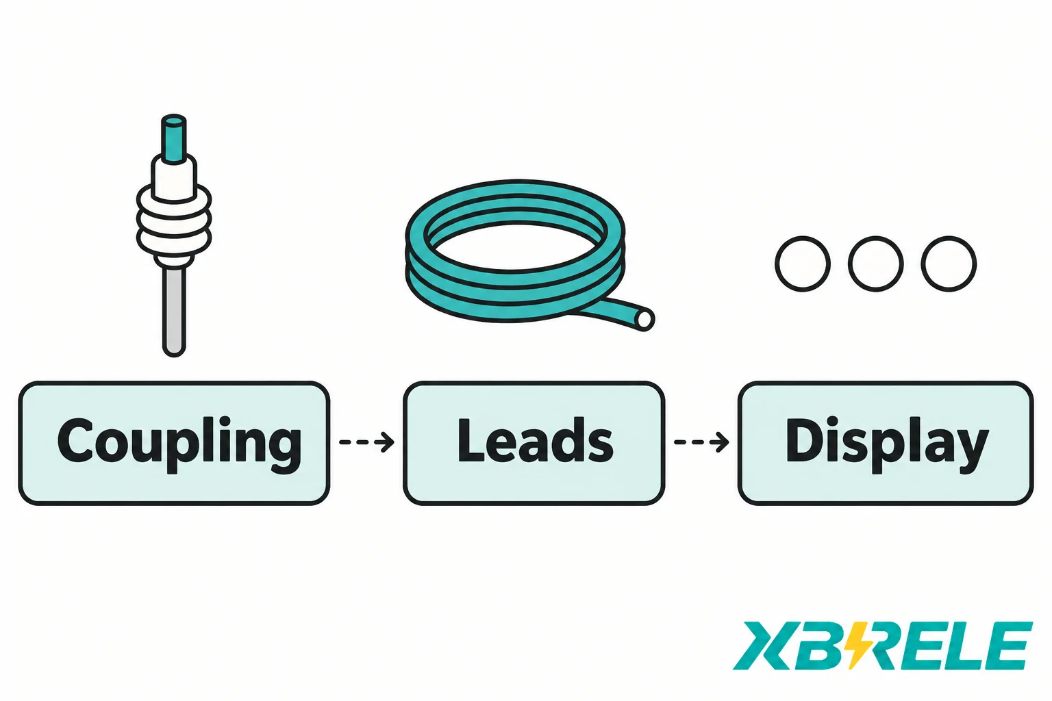
Draw the chain as three functional blocks and the replacement problem becomes obvious.
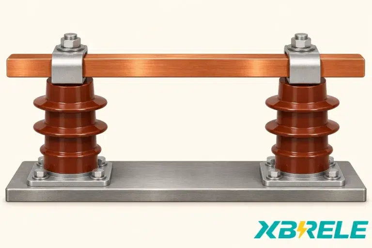
Coupling. Each phase needs a path from the primary conductor to the detection electronics. In the common medium-voltage case this is a capacitive electrode integrated into a post insulator, bushing or embedded pole — the same insulating component that already has to withstand the phase-to-earth voltage. The coupling capacitance between the high-voltage conductor and the sensing electrode passes a small displacement current into the specified secondary circuit.
Leads and interface. A screened or coaxial lead carries that current from the electrode to the device. The lead is not electrically neutral: its own capacitance to the earthed screen affects the secondary-side loading, and its screening and routing determine how much interference reaches the input. At the device end there is a connector or terminal arrangement — and, in the framework of the current standard, one defined interface.
Indicator and detection function. The device converts the input into a decision and a display. Internally it presents an input impedance, sometimes with a deliberate adjustment capacitance, and it compares the resulting quantity against thresholds.
Around those three blocks sit the earth reference and any limiting or protection elements, whose arrangement is part of the equipment design rather than an optional extra. The indicator measures with respect to the switchgear earth, so the reference path is part of the measurement, not just a safety connection. Any voltage-limiting and protection arrangement must remain as specified by the equipment manufacturer; its behavior cannot be inferred from the display alone.
An ideal capacitive-divider model helps explain the issue. If C1 is the primary coupling capacitance and the other terms are parallel secondary-side capacitances to earth, then:
This ideal model illustrates one reason compatibility matters; actual input impedance and protection elements require the manufacturer’s circuit data. A longer lead adds capacitance and reduces the indicated level. A device with a different input impedance changes the divider loading and may fall outside this ideal capacitive model. A replacement that expects an external adjustment capacitance the old installation never had, or that already includes one the old installation provided separately, shifts the whole operating point. The result is not necessarily a dead display — it is often a display that still lights, but lights at the wrong voltage, or fails to extinguish cleanly, or becomes marginal at the low end.
Not every chain is capacitive. The current scope covers capacitive, resistive and other coupling technologies, so installations can use other coupling principles and limiting arrangements. A capacitive-divider calculation tells you nothing useful about a resistive chain, and a device intended for one coupling principle is not automatically suitable for the other. This is one of the reasons why a catalogue description of “voltage presence indicator” is not enough to qualify a replacement.
The same primary voltage label appears on hardware built for completely different chains. Rated voltage tells you which system the equipment may be connected to; it says nothing about coupling capacitance, lead characteristics, input impedance, threshold set or interface. Two devices marked for the same system voltage and having the same bezel can be electrically incompatible.
The current position is straightforward. The first edition of IEC 62271-213, published in 2021, combines and replaces IEC 61243-5:1997 and IEC 62271-206:2011. It defines a single VDIS interface and an optional multipurpose output. Its scope covers a coupling system per phase, using capacitive, resistive or other technology, for systems above 1 kV at 16.7–60 Hz, and it addresses the detection and indication of the presence or absence of operating voltage. It does not claim to distinguish voltage that is not present, below 10 % of nominal, from a dead circuit at 0 V. Phase comparison is not part of it: that subject is covered by IEC 62271-215.
Three practical readings follow.
State the system and interface explicitly. For a project using this standard, specify VDIS and the required functions. Its standardized interface definition does not mean every primary coupling connector, signal output or mounting arrangement is interchangeable.
A replacement changes the specification basis. If the original installation was specified against IEC 61243-5 or IEC 62271-206, and the replacement is offered as compliant with IEC 62271-213, then you are moving between frameworks, not just between products. That is a legitimate thing to do — it is often the reason for the replacement — but the interface, the output function and the declared performance all need to be read in the new framework.
Standards replacement is not a retrofit mandate. The legacy publications being marked as replaced does not mean that every existing installation is unsafe, nor that replacement is legally required. Whether a site must move to the new edition depends on the project specification, on how and when the local standards body has adopted the edition, and on the asset owner’s own policy. Those are three separate questions that are frequently collapsed into one by a supplier’s marketing sentence. The engineering question — does the existing chain still do what the operating philosophy needs — is a fourth, and it is answered by inspection and records, not by a standard’s status page.
One boundary worth keeping sharp: IEC 62271-213 does not validate a phase-comparison accessory. If a panel carries phase-comparison sockets, or a replacement device offers phase comparison as an extra function, the appropriate system and interface approval comes from the phase-comparison side. Ordering a VDIS does not, on its own, re-qualify that function.
Matching a panel cutout addresses the mounting envelope. It cannot establish electrical compatibility or detection performance. What follows is the checklist that actually decides whether a candidate is viable.
| What to establish | Why it decides the outcome | Where it comes from |
|---|---|---|
| Switchgear type, OEM, panel drawing, original device model | Establishes the chain as designed, including the sensing circuit’s reference/earthing and limiting arrangements and how the leads are routed | Panel drawings, OEM documentation, the existing device’s nameplate |
| Nominal voltage and frequency | Sets the design point of the divider; the offered device’s documented operating range and permitted configuration must cover the actual system | Nameplate, system records, protection settings |
| Coupling principle and C1 value | Determines the divider ratio and the current available to the input | Sensor catalogue data, OEM data sheets, original type test records |
| Connecting lead type, length and capacitance | Adds to the denominator in the divider; screened construction and routing also affect interference behaviour | Panel wiring records, physical inspection |
| Interface type and permitted leads, connectors and terminations | Defines what the device will physically and electrically accept; a connector that mates is not the same as a connector with the same duty | Original device records; replacement manufacturer’s declared interface |
| Display and detection function, and self-test scope | Decides whether the installation provides presence information, an absence indication, or both, and what faults the device can report | Replacement manufacturer’s functional description |
| Mounting, IP rating and environment | Mechanical and environmental fit: door thickness, sealing, ambient temperature, condensation, vibration | Panel drawings, site conditions |
| Outputs, control supply and contact semantics | Determines what the remote system actually learns, and whether the output can be relied on for the purpose intended | Replacement device documentation, SCADA point list |
Four different questions are hidden in that table, and they must be answered separately. Mechanical fit asks whether the device sits correctly in the panel with proper sealing and access. Connector fit asks whether the lead terminates. Electrical match asks whether the divider — coupling, lead, input impedance, adjustment — produces the intended behaviour at the intended voltage. Verified function asks whether the assembled chain has been shown, by the manufacturer and by site acceptance, to perform as required.
The first two are cheap to check and the last two are where retrofits fail.
ال Kries CAPDIS-PI-HR_RR4 datasheet illustrates the point without needing any interpretation of its performance: the retrofit product’s ordering data explicitly require nominal voltage Un, the size of the coupling capacitor C1, and the existing interface type (HR, LRM and so on). A supplier that will not accept those three inputs cannot tell you whether its device matches your chain — it can only tell you that its device fits the hole.
ال Horstmann Wega documentation makes a related point about connectors. The product page and FAQ distinguish the coupling input, adjustment considerations and a dedicated signal output, and the manufacturer’s FAQ states that only the dedicated OUT port may forward the voltage signal, while the other connectors labelled IN are the switchgear coupling inputs. Identical-looking connectors on the same faceplate carry different duties. The implication for replacement work is general: never infer the duty of a connector from its shape, its pin count or its position on the panel.

Two temptations should be resisted. The first is improvising an adapter to mate a new device to an old lead. An adapter changes capacitance, screening and sometimes the reference path, and it is exactly the kind of change that is invisible afterwards. The second is trying to compensate for a mismatch by setting an adjustment capacitance from a rule of thumb. If the coupling capacitance is not known, the correct input is the record from the sensor manufacturer or the panel drawings — not a number chosen to make the display behave on the bench.
Modern devices commonly offer changeover contacts, sometimes a serial or network interface, so that voltage condition can be reported to SCADA. It is easy to assume that such a contact is a safe permissive for an interlocking or earthing scheme. It is not, unless someone has designed and verified it as one for that specific system.
The reason is that “the contact is closed” is an observation, not a meaning. Its meaning depends on which condition the device is mapping onto the contact, and on what the contact does when the device loses its auxiliary supply, loses its connection to a coupling electrode, fails a self-test, or recovers after a fault. A contact that opens on loss of supply looks the same to the remote logic as a contact that opens because voltage is absent. The same contact state could therefore mean reported absence of operating voltage or a loss of monitoring, depending on the design.
Any specification for remote reporting therefore needs explicit answers to a defined list of conditions:

Two information categories are being conflated in most of those bullets, and they should be separated in the design. Voltage state is what the chain reports about the primary circuit. System health is what the device reports about itself and its connections. Remote logic that receives only the first can be misled by a failure that silences the second; logic that receives only the second knows a detector is alive but nothing about the circuit. Where an installation matters, both are worth bringing back, and the point list should say which is which rather than leaving it to a commissioning engineer’s memory.
Two further cautions belong here. There is no universal NO/NC convention that makes a device’s contact interchangeable with another’s, so a replacement with a different default state can invert the sense of every downstream point without any visible change at the panel. And a self-test is a statement about coverage, not a guarantee about the whole chain: a device self-test may exercise the electronics, the display and part of the input path, but it may say nothing about the coupling electrode, the lead, or the reference connection. The right question to ask a manufacturer is not “does it self-test” but “what exactly does the self-test cover, and what does a pass and a fail each assert.”
The same discipline applies to a phase-comparison accessory. Its approval route runs through the phase-comparison framework, not through the VDIS specification, and a replacement device that happens to offer the function needs its system and interface compatibility confirmed in those terms.
Keep a replacement record that supports both the engineering decision and the order. A record assembled before the enquiry does three things: it lets a supplier answer with a matching device rather than a near one, it gives a reviewer something to check the proposal against, and it leaves the panel with a traceable history when the next replacement comes around.
A workable record contains:
Two conditional cases show how the record earns its keep.
Same cutout, different coupling capacitance. An indoor panel has an original indicator with a well-documented C1 from the sensor catalogue, and a candidate device that fits the cutout exactly and looks like a direct improvement. The candidate’s declared input arrangement assumes a different coupling capacitance range and expects an external adjustment element the panel does not have. The project should hold. The mechanical fit is satisfied, the connector may even mate, and the electrical match is unproven — which means the displayed thresholds would be unknown at the very voltages that matter. The correct next step is not an adapter or a guessed padding value; it is to obtain the C1 and the device’s declared input characteristics and let the manufacturer confirm or decline the combination.
Same coupling, different output semantics. A different panel has a chain that matches well on the electrical side, and the replacement offers the remote contact the operator wants. But the old device’s contact closed when voltage was present, while the new one closes when the system is healthy and opens on loss of supply — a defensible design, and completely different logic. Here the hardware fit and the divider both pass, and the failure would appear months later in an interlocking or alarm scheme. The record must capture the contact semantics explicitly and trigger a revalidation of the downstream logic, the point list and the alarm text before the panel returns to service.
XBRELE’s catalogue identifies CG5 capacitive sensors and their related indication use. That catalogue entry is a starting point for identifying a coupling element; it does not by itself establish a tested IEC 62271-213 VDIS comprising an existing sensor, an existing lead and a chosen display. Treat a sensor enquiry as a sensor enquiry.
Three routes are relevant. The capacitive sensor and post insulator range is where to start when the coupling element identity or C1 value is the missing piece. The wider switchgear parts directory covers related components when the replacement touches mounting, insulation or interconnection hardware. The contact page is where to submit the record described above.
When you submit, include the switchgear type and OEM, the original device model, the sensor identity and C1 if known, the interface type, the panel drawing reference, and photographs of the existing arrangement taken with the equipment isolated under the site’s own procedure — not with the panel live and the door open. State the functions you need to retain and any new ones you need. The reply can then be a compatibility discussion rather than a dimensional one.
No. An unlit indicator is consistent with no voltage, but it is equally consistent with a failed lamp, a broken lead, a failed control supply or a disturbed reference connection, unless the system provides additional validated diagnostic information. Presence-indicating arrangements are built to warn that voltage is there; silence from them is not evidence of absence. Establishing that operating voltage is absent is the job of a detecting function, and it still only takes you to a threshold rather than to a verified zero-volt, safe-to-access condition.
Only if the complete sensing chain and intended functions have documented compatibility. A VDIS is defined around a specific interface and its detection behaviour depends on the coupling capacitance, the lead and its own input characteristics. A device that fits the cutout and mates with the existing connector may still be electrically mismatched, and it may also change what the remote contacts mean. The practical test is whether a manufacturer will confirm compatibility against your stated Un, C1, lead and interface — not whether the new unit lights up when fitted.
No. Some switchgear families use a separate detector offered as an accessory, and that arrangement appears prominently in some manufacturers’ documentation, but it is one architecture rather than a definition. Many VDS and VDIS installations are integrated assemblies in which the coupling electrode, lead, electronics and display are permanently installed with no hand-held instrument involved. Assuming the external-tester pattern applies everywhere leads to specifying an inaccessible or non-existent accessory socket on a panel that never had one.
No. Phase comparison is handled separately, by IEC 62271-215. A device that offers phase-comparison sockets or an integrated comparison function in addition to voltage detection needs its phase-comparison capability qualified through the appropriate system and interface approval. Ordering a VDIS to the detection and indication framework does not re-validate a comparison accessory, and a retrofit that carries the accessory forward should show that function in its acceptance record separately from the voltage-state function.
“Operating voltage absent” is a threshold statement: the detected quantity has fallen below the level the system treats as operating voltage, judged against a boundary that the specified system defines. “Exact zero” is a physical claim about the circuit, and it is not something a threshold-based detector can make — the current framework states plainly that a VDIS does not distinguish a circuit whose voltage is not present from a dead circuit at 0 V. Neither statement is the same as “safe to touch,” which additionally depends on backfeed, parallel sources, induced voltage, trapped charge and the earthing state.