Need Full Specifications?
Download our 2025 Product Catalog for detailed drawings and technical parameters of all switchgear components.
Get CatalogDownload our 2025 Product Catalog for detailed drawings and technical parameters of all switchgear components.
Get CatalogDownload our 2025 Product Catalog for detailed drawings and technical parameters of all switchgear components.
Get Catalog
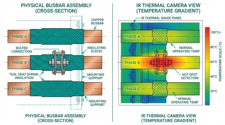
Busbar connections fail gradually. A properly torqued joint with clean contact surfaces carries rated current at 30–40°C above ambient. That same joint, undertorqued by 30%, runs 80–100°C above ambient within months as micro-gaps develop, contact resistance increases, and oxidation accelerates.
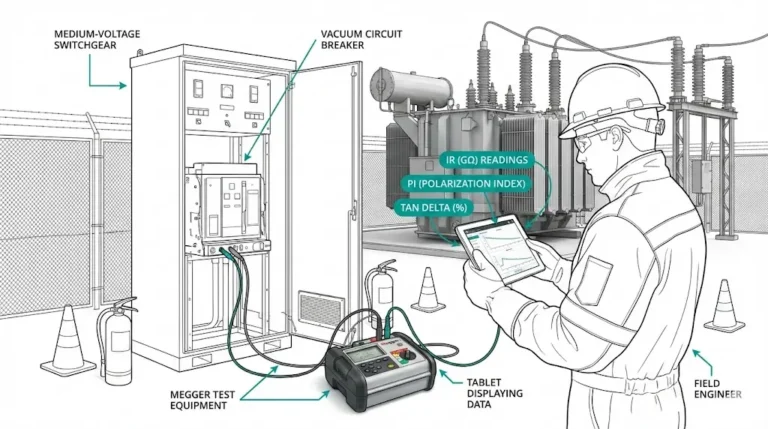
Hot busbar joints don’t announce themselves until thermal cameras catch them or infrared inspection reveals temperature differentials. By then, damage has started: annealing of copper reducing mechanical strength, oxidation reducing conductivity, progressive loosening from thermal cycling. The path from “slightly warm” to catastrophic failure shortens with each thermal cycle.
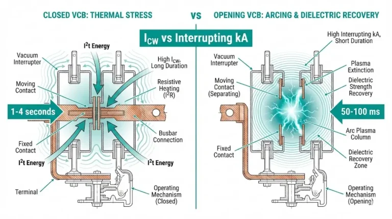
Medium-voltage switchgear busbar joints operate at currents from 630 A to 4,000 A. At these current levels, a 50% increase in contact resistance—from 10 μΩ to 15 μΩ—generates 2.25× more heat (P = I²R). A joint running 60°C over ambient at 1,600 A consumes roughly 400 W, enough to visibly glow under thermal imaging and rapidly degrade both the busbar and bolted connection.
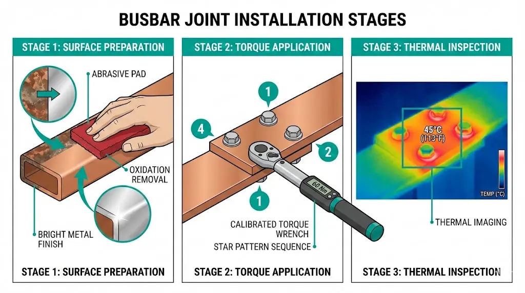
Preventing hot joints requires three elements executed correctly: proper surface preparation (removing oxidation and achieving metal-to-metal contact), correct torque application (creating sufficient contact pressure without damaging threads), and ongoing thermal monitoring (catching deterioration before failure).
This guide provides the specific procedures, torque values, and inspection criteria maintenance engineers need to install and maintain reliable busbar connections in vacuum circuit breaker switchgear and MV distribution systems rated 12–40.5 kV.
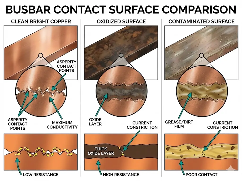
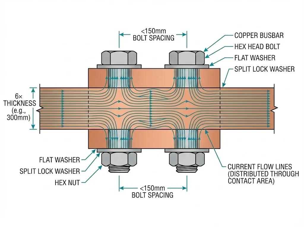
Electrical current crossing a bolted joint must pass through microscopic contact points where metal surfaces actually touch. Even machined flat surfaces contact only at asperity peaks—actual contact area is typically 1–10% of apparent joint surface area.
Contact resistance develops from:
Heat generation:
Power dissipated at joint: P = I² × R_contact
For a 1,600 A busbar joint:
That 128 W concentrated in a small joint volume creates localized temperatures exceeding 150°C—enough to anneal copper, melt plating, and accelerate oxidation.
Thermal cycling damage:
This positive feedback loop explains why hot joints deteriorate exponentially once started.
Copper oxidizes in minutes when exposed to air. Aluminum oxidizes even faster, forming tenacious aluminum oxide (Al₂O₃) with high electrical resistance.
For copper busbars:
For aluminum busbars:
Critical: Never mix dissimilar metals (copper-aluminum) without proper bimetallic transition washers/plates and joint compound. Galvanic corrosion rapidly degrades such joints.
Check flatness before assembly:
Warped busbars create uneven contact pressure—some areas make good contact while others gap, creating local hot spots even with correct overall torque.
Wrong fasteners compromise even perfect surface preparation.
For MV switchgear busbar joints:
Never use:
Flat washers:
Lock washers:
Application:
For aluminum busbars:
When to use:
Application:
Common products:
Correct torque creates metal-to-metal contact pressure while avoiding thread damage.
For copper busbar joints (indoor switchgear, clean dry conditions):
| Bolt Size | Grade 8.8/Class 5 | Grade 10.9/Class 8 |
|---|---|---|
| M8 | 22–25 N⋅m | 30–35 N⋅m |
| M10 | 40–50 N⋅m | 55–65 N⋅m |
| M12 | 70–85 N⋅m | 95–115 N⋅m |
| M16 | 150–180 N⋅m | 200–240 N⋅m |
| M20 | 300–360 N⋅m | 400–480 N⋅m |
For aluminum busbar joints:
Reduce torque by 15–20% compared to copper (softer metal, creeps under load)
| Bolt Size | Recommended Torque |
|---|---|
| M10 | 35–45 N⋅m |
| M12 | 60–75 N⋅m |
| M16 | 130–160 N⋅m |
Manufacturer specifications always override these general values.
Equipment required:
Procedure:
Torque wrench technique:
Overtorquing damage:
Undertorquing consequences:
Copper and aluminum both exhibit stress relaxation and creep under load.
Initial torquing: Creates elastic deformation in metal
Under load: Temperature cycles cause:
Result: 10–25% loss in clamping force within first weeks of operation
First re-torque: 48–72 hours after initial energization
Second re-torque: 30 days after commissioning
Subsequent intervals:
How to check:
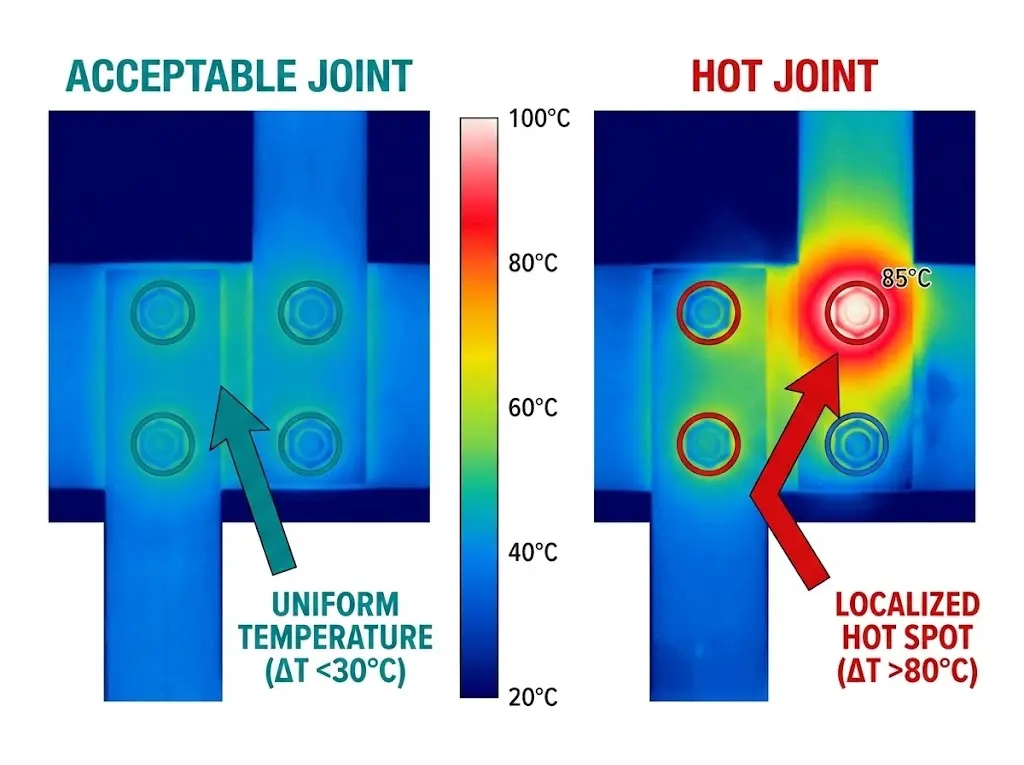
Thermal imaging catches degradation before catastrophic failure.
Equipment: Thermal imaging camera (FLIR, Fluke, etc.)
Inspection procedure:
Acceptance criteria:
| Temperature Rise (ΔT) | Assessment | Action |
|---|---|---|
| <30°C | Acceptable | Continue monitoring |
| 30–50°C | Elevated | Investigate during next outage, plan re-torque |
| 50–80°C | Hot joint | Schedule immediate corrective action |
| >80°C | Critical | Emergency shutdown, repair immediately |
Phase comparison:
In three-phase systems, compare similar joints across phases:
Uniform heating along busbar: Normal (I²R heating of conductor itself)
Localized hot spot at bolt:
Hot spot offset from bolt center:
One bolt hot, others normal in multi-bolt joint:
Progressive temperature gradient:
Annual inspection catches degradation before emergency failures.
Check for:
Vibration-prone installations:
Check for:
Frequency:
Procedure:
Document:
Equipment: Micro-ohmmeter (100 A+ test current)
Procedure:
Typical values:
Not typically performed for standard maintenance (thermal imaging more practical), but useful for troubleshooting specific hot joints or commissioning critical installations.
| Mistake | Consequence | Prevention |
|---|---|---|
| Skipping surface cleaning | Oxide layer causes high contact resistance | Always clean to bright metal before assembly |
| Using impact wrench for final torque | Overtorque, thread damage, uneven loading | Use calibrated torque wrench for final passes |
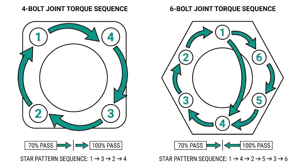
| Sequential torquing (1→2→3→4) | Joint distortion, uneven contact pressure | Always use star/cross pattern |
| Mixing copper/aluminum without joint compound | Galvanic corrosion, rapid failure | Use bimetallic transition plates or aluminum washers + compound |
| Single-pass torquing | Uneven bolt tension in multi-bolt joints | Use two-pass method (70% → 100%) |
| No re-torque after commissioning | Thermal cycling loosens joint | Re-torque after 48–72 hours operation |
| Over-lubricating bolt threads | Achieves higher tension than intended (torque spec assumes dry/lightly lubricated threads) | Apply compound only to contact surfaces, NOT threads |
| Reusing deformed washers | Uneven load distribution, poor contact | Replace washers if visibly deformed |
| Ignoring manufacturer torque specs | Incorrect clamping force for specific design | Always use manufacturer values if provided |
Joints carrying >2,000 A require extra attention.
Multi-bolt joints:
For wide busbars requiring multiple bolts:
Busbar overlap length:
Longer overlap distributes current, reduces current density at edges:
Silver or tin plating:
High-current busbars often plated:
Flexible braids for vibration:
Fixed busbar joints in vibration environments (generators, reciprocating equipment) crack from fatigue:
External Reference: IEC 62271-100 — IEC 62271-100 standard for high-voltage switchgear
Q1: Can I use an impact wrench to speed up busbar joint installation?
A: Use impact wrench only for initial snugging (30% final torque). ALWAYS use calibrated torque wrench for final torque passes—impact wrenches deliver inconsistent torque and frequently overtighten, damaging threads and yielding bolts.
Q2: How much does contact resistance increase due to oxidation on copper busbars?
A: Clean bright copper: ~5 μΩ contact resistance. Light tarnish: 15–25 μΩ. Heavy oxidation (dark brown/black): 50–200 μΩ. This 10–40× increase explains why surface cleaning is mandatory—oxidation alone can cause joint failure regardless of torque.
Q3: What torque should I use for stainless steel bolts in aluminum busbars?
A: Reduce standard aluminum torque by additional 10% (total 25–30% below copper spec). Stainless steel has higher friction coefficient than zinc-plated steel, achieving higher clamping force for same applied torque—risk of crushing aluminum if full torque applied.
Q4: How often should I perform thermal imaging on busbar joints?
A: Annually minimum for indoor installations, semi-annually for outdoor or harsh environments. Perform additional inspection after any fault event, overload condition, or maintenance work on adjacent equipment. Critical facilities (data centers, hospitals) may scan quarterly.
Q5: Can I repair a hot joint by simply re-torquing without disassembly?
A: If ΔT <50°C and bolts turn significantly when checked, re-torquing may suffice. If ΔT >50°C or bolts don’t turn (indicating oxidation/contamination rather than loose bolts), must disassemble, clean surfaces to bright metal, and re-assemble properly. Attempting to fix severe oxidation with torque alone compresses oxide layer but doesn’t remove it.
Q6: What’s the difference between joint compound and thread anti-seize?
A: Joint compound (e.g., Penetrox) contains conductive particles (zinc, copper) and prevents oxidation at contact surfaces—apply to busbar surfaces. Thread anti-seize (copper or nickel-based) prevents thread galling and eases future disassembly—apply to bolt threads. DO NOT confuse—using thread anti-seize on contact surfaces provides no electrical benefit and may increase contact resistance.
Q7: How do I handle dissimilar metal joints (copper busbar to aluminum equipment terminal)?
A: Use bimetallic transition washer/plate (copper one side, aluminum other side, explosion-bonded or mechanically joined). Apply aluminum-rated joint compound to aluminum side. Alternatively, use all-aluminum hardware (washers, bolts if possible) and compound on both surfaces. Never bolt copper directly to aluminum without transition—galvanic corrosion destroys joint in months.