Need Full Specifications?
Download our 2025 Product Catalog for detailed drawings and technical parameters of all switchgear components.
Get CatalogDownload our 2025 Product Catalog for detailed drawings and technical parameters of all switchgear components.
Get CatalogDownload our 2025 Product Catalog for detailed drawings and technical parameters of all switchgear components.
Get Catalog
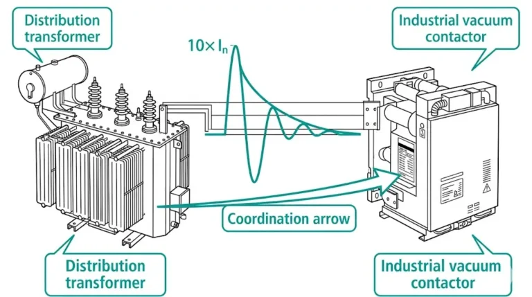
Capacitor duty contactors face operational demands that destroy standard switching devices within months. When a contactor energizes a discharged capacitor bank, inrush currents surge to 80–100 times nominal current in the first quarter cycle—a stress level that welds contacts, erodes surfaces, and triggers cascading failures across power factor correction systems.
This guide examines the physics behind capacitor switching stress, explains how detuning reactors modify contactor requirements, compares inrush limitation strategies, and provides field-proven diagnostic procedures for identifying failure modes before they cause unplanned outages.
Standard AC contactors rated for motor starting or resistive loads fail rapidly in capacitor switching service. The physics of capacitor energization creates electrical stresses exceeding typical design margins by an order of magnitude.
The inrush current problem
A discharged capacitor bank presents near-zero impedance at the instant of energization. Current magnitude is limited only by circuit inductance (typically 50–200 μH for bus connections) and system resistance. The resulting oscillatory inrush follows LC resonant behavior with frequencies commonly ranging from 2–15 kHz—far exceeding 50/60 Hz power frequency.
The peak inrush current magnitude can be expressed as: Ipeak = Vpeak × √(C/L), where Vpeak represents the instantaneous voltage at contact closure, C is the capacitor bank capacitance, and L is the total circuit inductance. For a typical 400V system with 500 μF capacitance and 100 μH inductance, theoretical inrush peaks can exceed 1,400 A from a 50 A nominal rated bank.
For a 200 kvar, 400 V capacitor bank drawing 290 A steady-state, first-cycle inrush can exceed 25 kA for 2–3 milliseconds. Standard motor contactors rated for 8–10× locked rotor current cannot survive this duty.
Transient recovery voltage at de-energization
When a contactor opens to de-energize a capacitor bank, current passes through zero but the capacitor retains charge. Voltage across opening contacts rises rapidly—transient recovery voltage (TRV) can exceed 2.0 per-unit within microseconds. If contact gap dielectric strength lags behind TRV rise, restrike occurs: the arc re-establishes, current flows again, and the cycle repeats. Multiple restrikes escalate voltage with each event.
According to IEC 62271-106, capacitor switching contactors must withstand at least 100 times rated current during inrush while maintaining contact integrity through 10,000 operations at full inrush levels.

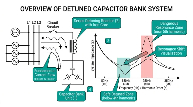
Detuned capacitor banks incorporate series reactors—typically 5.67%, 7%, or 14% impedance at 50 Hz—to shift resonant frequency below dominant harmonic orders. This configuration fundamentally alters contactor selection criteria.
Reduced inrush severity
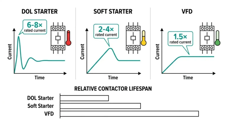
The series reactor limits di/dt during energization. Peak inrush drops from 100×+ to 20–30× rated current in properly detuned systems. However, this reduction comes with trade-offs that affect contactor sizing.
Increased steady-state current
Reactor voltage drop requires oversizing capacitors by 5–15% to deliver target kvar output. Contactors must handle this elevated continuous current. The relationship follows: I_actual = I_nominal / √(1-p), where p represents the detuning percentage.
| Detuning Factor | Tuning Frequency (50 Hz) | Target Harmonic Avoidance | Current Multiplier |
|---|---|---|---|
| 5.67% | 210 Hz | Below 5th (250 Hz) | 1.03× |
| 7% | 189 Hz | Below 5th with margin | 1.04× |
| 14% | 134 Hz | Below 3rd (150 Hz) | 1.08× |
Altered TRV profile
The reactor-capacitor L-C circuit modifies de-energization transient shape. TRV waveform frequency decreases, extending time-to-peak. Contactors must still handle TRV magnitude, but the slower rise rate reduces restrike probability in vacuum contactors designed for capacitor switching duty.
In installations with high 3rd harmonic content from LED lighting or VFDs without DC chokes, 14% detuning is increasingly common—requiring contactors rated for 8–10% higher continuous current.
Field experience across industrial power factor correction systems reveals three proven approaches to managing capacitor switching stress. Each involves distinct trade-offs between complexity, cost, and effectiveness.
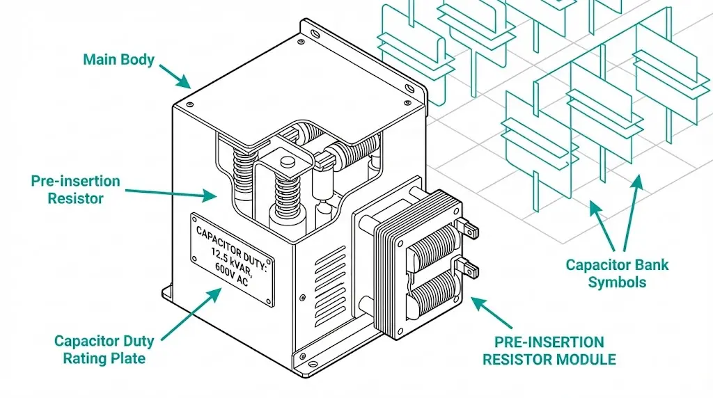
Pre-insertion resistors (PIR)
A resistor of 1–5 Ω is inserted in series during initial contact closure. After 10–20 ms, main contacts bypass the resistor. This approach reduces peak inrush to 10–20× rated current—a 70–85% reduction from uncontrolled switching.
CKG vacuum contactors with integrated pre-insertion resistors are widely deployed in medium-voltage capacitor bank applications where PIR coordination is factory-optimized.
Controlled switching (point-on-wave)
Synchronous closing timed to voltage zero-crossing eliminates the DC offset component of inrush current. This method achieves 90–95% inrush reduction but requires electronic controllers and consistent mechanism operating time—typically ±1 ms repeatability.
Permanent current-limiting reactor
A fixed series reactor remains in circuit permanently. Simple and reliable with no moving parts beyond the contactor itself. However, the reactor adds 2–4% continuous losses and requires dedicated space and cooling provisions.
| Strategy | Inrush Reduction | Complexity | Relative Cost | Maintenance Focus |
|---|---|---|---|---|
| Pre-insertion resistor | 70–85% | Medium | Medium | Resistor inspection |
| Controlled switching | 90–95% | High | High | Controller calibration |
| Permanent reactor | 50–70% | Low | Medium-High | Thermal monitoring |

[Expert Insight: Switching Strategy Selection]
- Back-to-back capacitor bank switching produces 5–10× higher inrush than isolated bank energization—factor this into strategy selection
- PIR failure is progressive: monitor resistor temperature during switching campaigns
- Controlled switching ROI improves dramatically above 50 operations per day
- Hybrid approaches (PIR + controlled switching) are emerging for critical installations
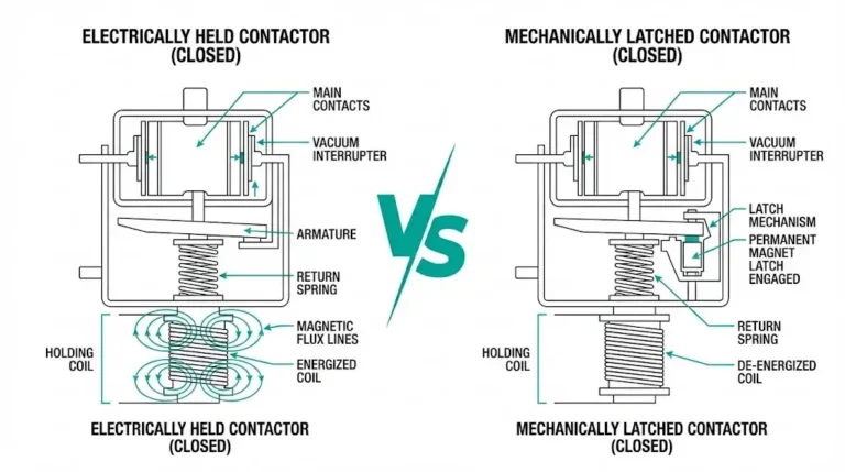
Vacuum contactors demonstrate measurably superior performance in capacitor switching applications. The physics of vacuum arc interruption directly addresses the failure mechanisms that destroy air-break designs.
Dielectric recovery rate
Vacuum gaps recover dielectric strength at >20 kV/μs after current zero—substantially faster than air gaps at 0.1–0.5 kV/μs. This rapid recovery prevents arc re-establishment during contact separation, limiting restrike probability to <0.1% in well-designed units versus 2–5% for air-break contactors.
Contact erosion resistance
Vacuum arcs constrict to small cathode spots rather than spreading across contact surfaces. Cu-Cr contact material loss measures 10–50× lower per operation compared to AgCdO or AgSnO₂ contacts in atmospheric environments. This translates directly to extended service intervals.
Restrike physics
After current interruption, TRV rises across the opening gap. If TRV exceeds dielectric strength before contacts reach full separation, restrike occurs. Vacuum interrupters with Cu-Cr contacts maintain dielectric strength even at partial contact separation distances of 2–4 mm, providing margin against restrike during the critical opening phase.
The compact vacuum arc chamber eliminates arc chutes and gas handling—simplifying maintenance while improving reliability in contaminated industrial environments.
From maintenance assessments across 200+ industrial power factor correction installations, four failure modes account for over 85% of capacitor duty contactor replacements. Early detection prevents cascading damage to capacitor banks and upstream protection systems.
Contact welding
Inrush currents exceeding contactor making capacity cause localized melting at temperatures above 1,080°C (copper melting point). Micro-welds progressively degrade switching performance until the contactor locks closed. Contact welding correlates strongly with inadequate pre-insertion resistor selection or worn damping components.
Symptoms: Contactor fails to open; capacitor bank remains energized; control circuit indicates “open” while power circuit remains closed.
Restrike damage
Multiple restrikes during opening generate voltage escalation. Each restrike adds energy to the system, potentially exceeding capacitor dielectric ratings. Capacitor bank failures attributed to “defective capacitors” often originate from contactor restrike events.
Symptoms: Capacitor can rupture; contactor shows internal arc tracking; fuses blow at de-energization rather than energization.
Pre-insertion resistor burnout
Exceeding resistor I²t rating through high switching frequency or undersizing causes progressive overheating. When the resistor fails open-circuit, subsequent closures see full uncontrolled inrush.
Symptoms: Gradual increase in measured inrush current; resistor discoloration visible during inspection; eventual contact welding following resistor failure.
Operating mechanism degradation
Frequent cycling combined with transient voltage spikes on control circuits stresses coil insulation and mechanical linkages. Coil resistance deviation >15% from nameplate indicates thermal degradation.
Symptoms: Delayed operation; failure to close consistently; audible mechanism hesitation.

Systematic inspection following documented procedures extends contactor service life while preventing catastrophic failures. This protocol applies to both scheduled maintenance and troubleshooting after operational anomalies.
Contact resistance measurement
Measure resistance across main poles using a micro-ohmmeter. Values exceeding 100 μΩ indicate significant erosion requiring evaluation against manufacturer erosion limits. Trending contact resistance over time provides early warning of approaching end-of-life.
Pre-insertion resistor verification
Where equipped, verify PIR integrity using continuity testing. Measure actual resistance value and compare to nameplate—deviation >20% suggests thermal damage. Inspect resistor housing for discoloration or cracking.
Vacuum bottle inspection
On medium-voltage units, inspect vacuum interrupter bottles for internal discoloration indicating contact material deposition. External deposits on ceramic envelopes suggest contamination requiring cleaning. JCZ series maintenance specifications provide detailed inspection criteria.
Mechanical linkage assessment
Check mechanical linkage free-play against manufacturer specifications—typically below 0.5 mm. Excessive play causes inconsistent contact timing, increasing restrike probability.
Operation counter review
Compare accumulated operations against rated mechanical endurance (typically 100,000–300,000 operations). Contactors approaching 80% of rated life warrant increased inspection frequency or proactive replacement planning.
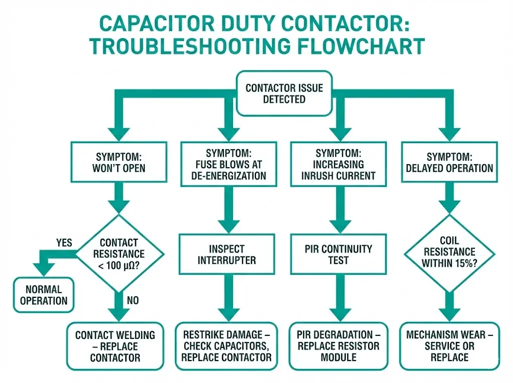
| Symptom | Likely Cause | First Diagnostic Step |
|---|---|---|
| Contactor won’t open | Contact welding | Measure contact resistance (<100 μΩ acceptable) |
| Capacitor fuse blows at de-energization | Restrike voltage escalation | Inspect interrupter; review TRV if monitoring available |
| Increasing inrush current trend | PIR degradation | Verify resistor continuity and value |
| Delayed or inconsistent operation | Mechanism wear or coil degradation | Measure coil resistance; check linkage free-play |
[Expert Insight: Maintenance Timing]
- Inspect after every 10,000 operations or annually, whichever comes first
- Auxiliary contact failure often precedes main contact problems—monitor control circuit anomalies
- Document contact resistance at each inspection to establish degradation trends
- Environmental contamination accelerates failure; increase frequency in dusty or corrosive atmospheres
Proper contactor selection prevents the failure modes described above. This checklist addresses the parameters that determine successful capacitor switching performance.
System voltage and insulation coordination
Match contactor rated voltage and basic insulation level (BIL) to system class: 7.2 kV, 12 kV, or 24 kV for medium-voltage applications. Altitude above 1,000 m requires voltage derating of approximately 1% per 100 m [VERIFY STANDARD: IEC 62271-1 clause for altitude correction factor].
Current calculations
Calculate steady-state current: I = kvar / (√3 × kV). For detuned banks, multiply by the current factor from the detuning table above. Select contactor continuous current rating with 10–15% margin.
Inrush current estimation
Isolated bank switching typically produces 50–100× rated current inrush. Back-to-back switching between parallel banks can generate 200×+ rated current due to discharge from adjacent energized banks. Verify contactor making current rating exceeds calculated worst-case inrush.
Switching frequency classification
| Application Type | Operations per Day | Recommended Contactor |
|---|---|---|
| Manual PFC | <10 | Standard capacitor contactor |
| Automatic PFC | 20–50 | High-endurance capacitor contactor |
| Fast-response PFC | >100 | Vacuum contactor mandatory |
Environmental considerations
Ambient temperature above 40°C requires current derating or improved ventilation. Contaminated environments benefit from vacuum contactors’ sealed interrupter design. High humidity installations need enhanced insulation specifications.
For capacitor bank installations requiring reliable, low-maintenance switching performance:
CKG series vacuum contactors feature integrated pre-insertion resistors optimized for medium-voltage capacitor bank duty. Factory-coordinated PIR timing eliminates field adjustment requirements.
JCZ series provides compact solutions for indoor switchgear with electrical endurance ratings exceeding 100,000 operations at full capacitor switching duty.
Custom engineering support addresses detuned reactor coordination, back-to-back bank configurations, and installations in extreme ambient conditions.
→ Contact XBRELE’s engineering team to discuss capacitor switching application requirements and receive sizing recommendations based on your specific installation parameters.
Q: What current rating should a capacitor duty contactor have?
A: Select a contactor with making current capacity of at least 100× rated current for isolated banks; back-to-back configurations between parallel banks may require 200×+ making current capability due to discharge from adjacent energized capacitors.
Q: Can standard motor contactors switch capacitor banks?
A: Motor contactors lack the making current capacity and restrike withstand required for capacitor service—using them typically results in contact welding within weeks to months depending on switching frequency.
Q: How does a detuning reactor affect contactor selection?
A: Detuning reactors reduce inrush severity to 20–30× rated current but increase steady-state current by 3–8% depending on detuning percentage, requiring corresponding adjustment in contactor continuous current rating.
Q: Why do vacuum contactors have lower restrike rates?
A: Vacuum gaps recover dielectric strength at >20 kV/μs compared to 0.1–0.5 kV/μs for air gaps, allowing the contact gap to withstand transient recovery voltage before restrike can occur.
Q: How often should capacitor duty contactors be inspected?
A: Perform inspection after every 10,000 operations or annually—whichever occurs first—with increased frequency in contaminated environments or for contactors approaching 80% of rated mechanical life.
Q: What causes pre-insertion resistors to fail?
A: PIR failure results from exceeding the resistor’s energy rating (I²t) through high switching frequency, resistor undersizing for the bank’s inrush energy, or inadequate cooling in enclosed installations.
Q: When is controlled switching worth the additional investment?
A: Controlled switching provides favorable return on investment for automatic PFC systems exceeding 50 operations per day, where the 90–95% inrush reduction substantially extends contact life and reduces capacitor stress compared to PIR-only approaches.