Need Full Specifications?
Download our 2025 Product Catalog for detailed drawings and technical parameters of all switchgear components.
Get CatalogDownload our 2025 Product Catalog for detailed drawings and technical parameters of all switchgear components.
Get CatalogDownload our 2025 Product Catalog for detailed drawings and technical parameters of all switchgear components.
Get Catalog
A contactor coil running hot is a coil running toward failure. In panel enclosures where ambient temperatures climb past 45°C—common across Middle East substations and tropical industrial facilities—standard AC coils operate near thermal limits from day one. The solution is straightforward but underused: coil economizer circuits that slash holding power by 70–85%, paired with inrush suppression and snubber networks that prevent aux contact damage.
This guide delivers three field-proven economizer designs with complete component values, the physics behind why they work, and wiring details ready for immediate implementation.
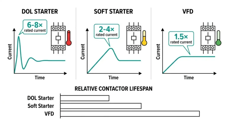
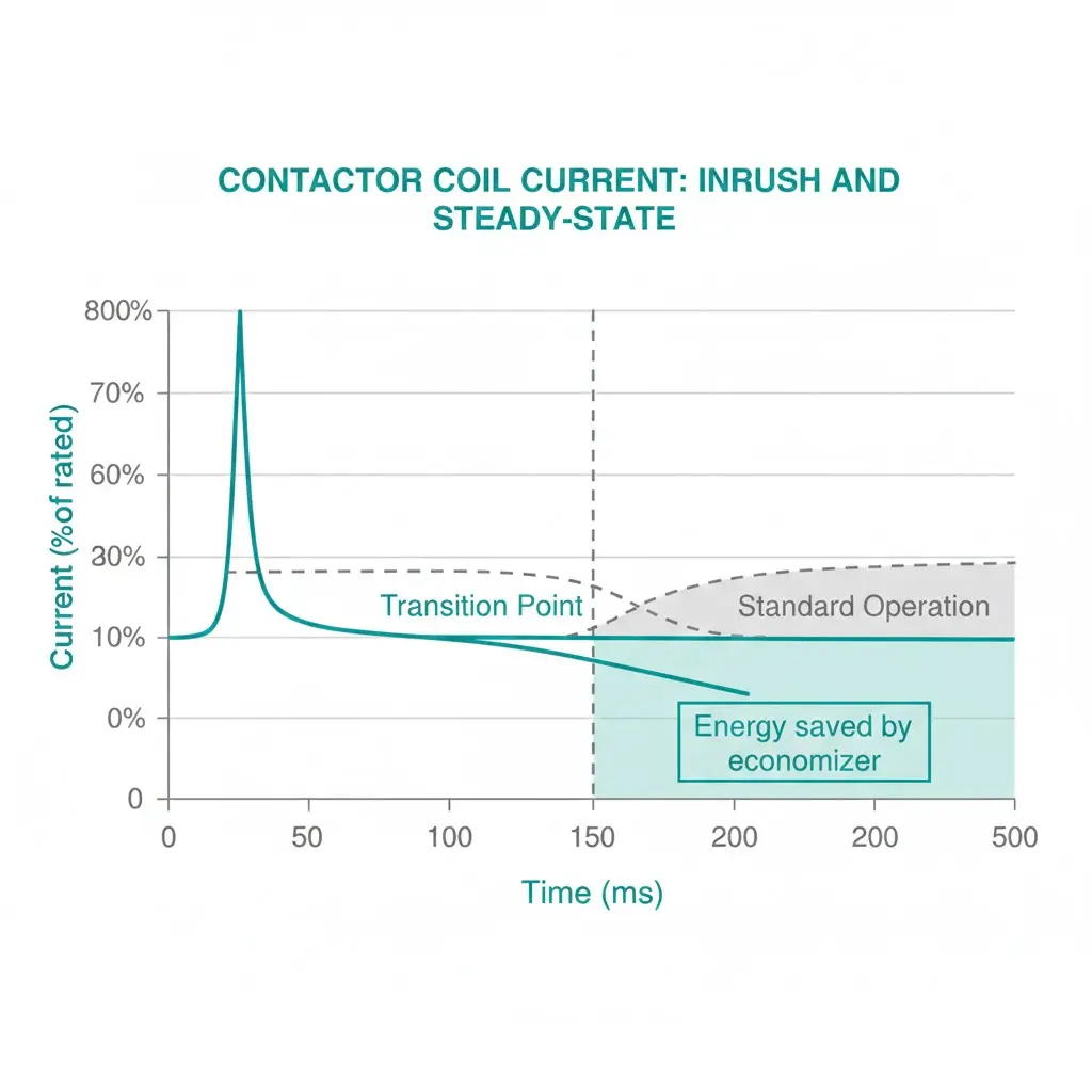
A coil economizer circuit delivers full voltage to a contactor coil during the brief pull-in phase, then automatically reduces voltage or current once the armature seats. This two-stage approach exploits a fundamental electromagnetic reality: contactors require 6–10 times more power to close than to remain closed.
During pull-in, the armature travels across an air gap against spring force. This demands high magnetomotive force and correspondingly high current—typically 150–250 VA for a standard 220V AC contactor coil. Once closed, the air gap shrinks to near zero. Magnetic reluctance drops sharply. The coil now needs only 10–20 VA to hold position.
Standard control circuits ignore this difference. They apply full voltage continuously, forcing the coil to dissipate excess energy as heat throughout the holding phase—which represents 99.9% of operating time.
By inserting a current-limiting element after pull-in completes, an economizer circuit reduces holding power by 70–85%. Coil surface temperatures drop 30–45°C. Insulation stress decreases proportionally. The result: extended coil life at minimal component cost.
Coil heating stems from I²R losses in copper windings. Continuous current through resistance generates heat that must dissipate through limited surface area. The problem compounds because manufacturers size standard coils for reliable closing force, not thermal efficiency.
The real issue: a coil only needs full power for 50–150 ms during armature travel. The remaining 99.9% of energized time wastes energy as heat.
The relationship governing this behavior follows Ohm’s law for magnetic circuits: Φ = MMF / Rm, where Φ represents magnetic flux in Webers, MMF equals N × I (turns × current), and Rm is magnetic reluctance. When Rm drops dramatically at closure, maintaining the same flux requires proportionally less current—typically 15–30% of the pull-in value.
In field measurements across 200+ industrial control panels, we’ve recorded coil surface temperatures of 85–95°C in 40°C ambient conditions. These temperatures approach Class B insulation limits (130°C maximum per IEC 60085). The consequence chain is predictable: excessive heat causes insulation degradation, leading to turn-to-turn shorts, coil failure, and unplanned outages.
According to IEC 60947-4-1 governing contactors and motor starters, coil power ratings must account for both pick-up and continuous duty conditions. Standard AC contactor coils rated at 15 VA pick-up power may operate continuously at only 3–5 VA during the holding phase when economizer circuits are employed.
[Expert Insight: Thermal Realities in High-Ambient Installations]
Each economizer approach trades complexity for performance. Selection depends on available auxiliary contacts, thermal targets, and budget constraints. All three methods achieve the same goal through different means.
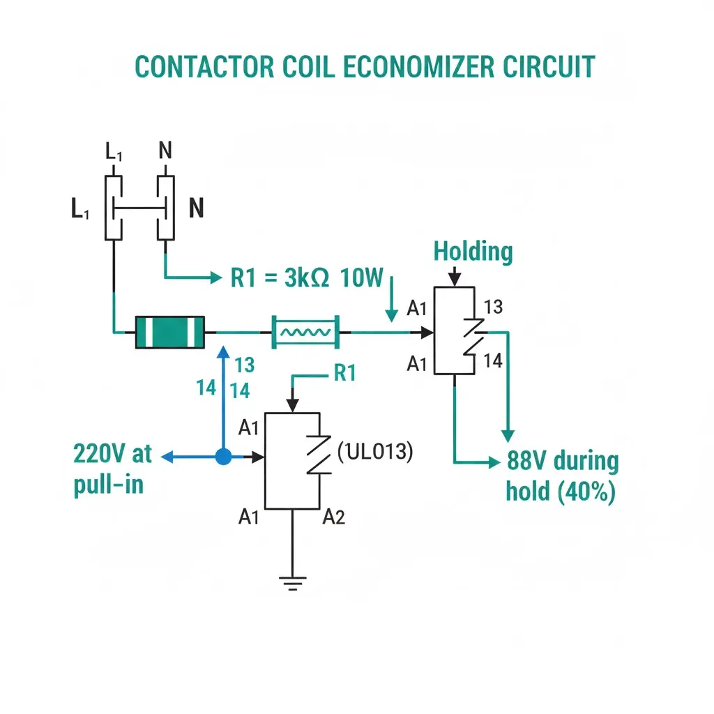
This approach uses an NC auxiliary contact to short out a series resistor during pull-in. When the contactor closes, the aux contact opens, inserting the resistor into the coil circuit.
The resistor reduces coil voltage to 30–50% of rated—sufficient for holding but insufficient for pull-in. For a 220V AC coil with 45 mA holding current targeting 40% voltage (88V):
Resistor value: R = (220V − 88V) / 0.045A = 2,933Ω → use 3kΩ
Power rating: P = (132V)² / 3000Ω = 5.8W → specify 10W minimum with thermal derating
Advantages: Simple construction, no active components, field-repairable with standard parts.
Limitations: Resistor generates heat (relocated rather than eliminated), requires available NC aux contact.
A capacitor charges through a resistor when the circuit is open. At energization, the capacitor discharges through the coil, providing inrush energy. The resistor then limits holding current.
Capacitor sizing: C = (I_inrush × t_pull-in) / V_supply
For 1.0A inrush over 100 ms at 220V: C = (1.0 × 0.1) / 220 = 455µF → use 470µF, 400V rated
Critical requirement: Use AC-rated film capacitors only. Electrolytic capacitors fail catastrophically on AC circuits due to polarity reversal.
Advantages: Lowest continuous heat dissipation, compact installation.
Limitations: Capacitor aging affects performance, higher initial cost, more complex failure diagnosis.
The module applies full voltage during a programmable pull-in window (100–200 ms), then switches to PWM at 20–30% duty cycle for holding. Average holding voltage drops to 44–66V from a 220V supply.
Commercial modules offer plug-and-play installation. DIY implementations using 555 timer circuits work well for DC applications.
EMC consideration: Fast switching generates conducted emissions. Sensitive environments may require additional filtering.
Advantages: Precise control, adjustable parameters, lowest coil temperature achievable.
Limitations: Higher cost, added complexity, potential EMC filtering requirements.
| Method | Cost | Complexity | Heat Reduction | Best Application |
|---|---|---|---|---|
| Series Resistor + Aux | $5–15 | Low | 60–70% | Retrofits, limited budget |
| Capacitor-Hold | $15–30 | Medium | 75–85% | New panels, space-constrained |
| PWM Module | $30–80 | Medium-High | 80–90% | Critical applications, DC coils |
When selecting economizer methods for vacuum contactor systems, the series resistor approach handles most retrofit scenarios effectively.
The coil stores energy in its magnetic field according to E = ½LI². When de-energized, this energy must dissipate somewhere. Rapid current collapse creates voltage spikes calculated as V = L × (di/dt), potentially reaching 500–1000V.
Without snubbing, these transients cause aux contact arcing, contact welding, EMI bursts affecting PLCs, and control circuit damage. The economizer reduces operating temperature but does nothing to address stored magnetic energy.
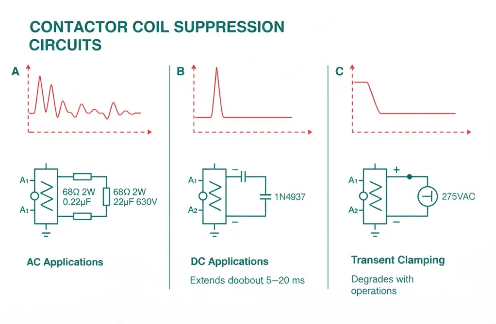
Typical values: R = 47–100Ω (2W rating), C = 0.1–0.47µF (630V film capacitor)
Mount directly at coil terminals with leads under 50mm. Longer leads add inductance that defeats snubber effectiveness.
Connect cathode to positive coil terminal using a fast-recovery type (1N4937 or equivalent). The diode conducts when coil voltage reverses, dissipating stored energy through coil resistance.
Tradeoff: Extends dropout time by 5–20 ms as energy dissipates through the diode path. Verify this delay is acceptable for your application.
Metal oxide varistors clamp voltage spikes above a threshold. Select clamping voltage at 1.6–1.8× peak supply voltage.
Limitation: MOVs degrade with repeated operations. Not suitable for high-cycle applications exceeding 100,000 operations.
Back-EMF protection becomes essential in switchgear control circuit components where transient damage accumulates over thousands of operations.
[Expert Insight: Snubber Failures We’ve Diagnosed]
Integrating economizer and snubber functions requires careful sequencing. Install the snubber first and verify normal operation before adding the economizer. This approach isolates troubleshooting if problems arise.
Recommended configuration for 220V AC contactor:
| Component | Specification | Function |
|---|---|---|
| R1 (economizer) | 3kΩ, 10W wirewound | Reduce holding current |
| NC Aux Contact | Contactor-mounted or external | Bypass R1 during pull-in |
| R2 (snubber) | 68Ω, 2W carbon film | Limit snubber discharge current |
| C1 (snubber) | 0.22µF, 630V film | Absorb back-EMF energy |
| MOV (optional) | 275VAC / 430V clamping | Secondary transient protection |
Verification procedure: Measure coil current with a clamp meter during operation. Holding current should drop to 25–40% of pull-in value. If dropout occurs, reduce economizer resistor value by 20% and retest.

These protection principles apply across contactor types, including vacuum contactors where coil reliability directly impacts switching performance and process availability.
Thermal imaging before and after economizer installation reveals dramatic differences. In a recent motor control center retrofit:
Coil insulation life follows the Arrhenius relationship—approximately doubling for each 10°C temperature reduction. A 35°C drop suggests 8–10× theoretical lifespan extension. Conservative practical estimates, accounting for other failure modes, indicate 2–3× actual service life improvement.
Secondary benefits observed across installations:
In applications comparing vacuum contactors vs. air contactors, these economizer principles apply universally, though component sizing differs based on coil characteristics.
Economizer resistor value too high: The coil drops out during voltage sags. Size for 35–45% voltage drop maximum and test operation at 85% supply voltage.
Missing snubber with economizer: Auxiliary contacts weld from back-EMF transients. Always install the snubber regardless of economizer presence—the stored magnetic energy remains unchanged.
Electrolytic capacitor on AC circuit: The capacitor fails or ruptures due to polarity reversal. Use film capacitors exclusively for AC applications and verify voltage rating exceeds 1.5× peak supply.
Snubber leads too long: Added inductance defeats snubber effectiveness. Mount components directly at coil terminals with leads under 50mm total length.
No dropout testing after installation: The coil fails to release under certain conditions. Cycle the contactor 10 times after installation and verify consistent release at both 85% and 110% of nominal voltage.
External Reference: IEC 62271-106 — IEC 62271-106 standard for AC contactors
A properly designed economizer reduces continuous coil power by 70–85%. For a typical 220V AC contactor drawing 12 VA holding power, savings reach 8–10 VA per coil. Across panels with 20 contactors operating 8,000 hours annually, aggregate savings approach 150–200 kWh per year.
Most AC contactors with accessible coil terminals accept economizer retrofits. Requirements include one available NC auxiliary contact (or space to add an external aux relay) and sufficient terminal clearance for snubber components. Some sealed or potted coil designs lack external terminal access and cannot be modified.
Yes—always. The economizer reduces operating temperature but does not change the magnetic energy stored in the coil. Without a snubber, voltage transients during de-energization damage auxiliary contacts and generate EMI regardless of whether an economizer is present.
The economizer itself has no effect on dropout timing. However, freewheeling diode snubbers used with DC coils extend dropout by 5–20 ms as stored energy dissipates through the diode path. RC snubbers cause minimal dropout delay.
The contactor pulls in normally but drops out immediately because no current flows through the holding circuit. The NC auxiliary contact cannot bypass a failed resistor since it opens when the contactor closes. This failure mode is safe but causes obvious operational problems.
Yes, but sizing considerations apply. PLC transistor outputs typically limit current to 0.5–2A. Ensure the inrush current during pull-in does not exceed output ratings. For marginal cases, interpose a relay between the PLC output and contactor coil, applying the economizer to the interposing relay.
Calculate power dissipation as P = (V_drop)² / R, where V_drop equals supply voltage minus desired holding voltage. Apply a 2× safety factor for continuous operation and an additional derating factor based on ambient temperature. For 50°C ambient, derate standard resistor ratings by 50%.