Need Full Specifications?
Download our 2025 Product Catalog for detailed drawings and technical parameters of all switchgear components.
Get CatalogDownload our 2025 Product Catalog for detailed drawings and technical parameters of all switchgear components.
Get CatalogDownload our 2025 Product Catalog for detailed drawings and technical parameters of all switchgear components.
Get Catalog
Every relay coil, contactor coil, and solenoid stores energy in its magnetic field during normal operation. The moment a control switch opens or a PLC output de-energizes, that stored energy must dissipate—and physics dictates exactly how destructive that process becomes without proper intervention.
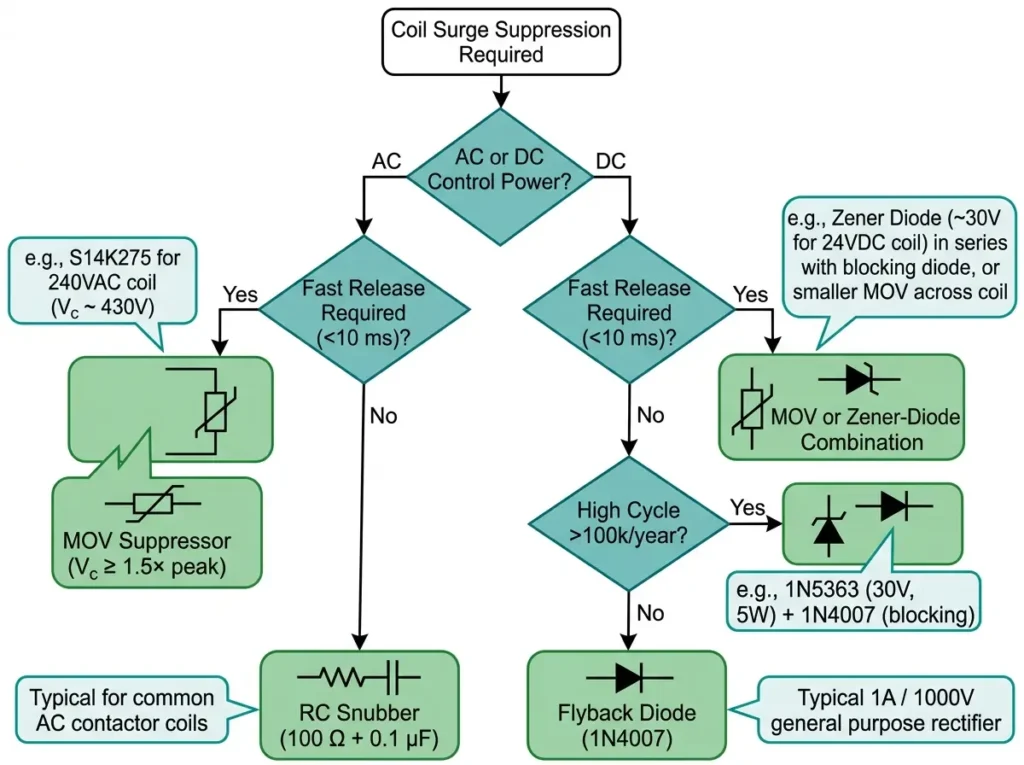
Three surge suppression technologies dominate industrial practice: metal oxide varistors (MOVs), RC snubber networks, and freewheeling diodes. Each operates through distinct mechanisms, and selecting incorrectly causes either inadequate transient protection or unacceptably slow coil release. This comparison guide provides the engineering logic for matching suppressor type to AC or DC control power in relay and contactor applications.
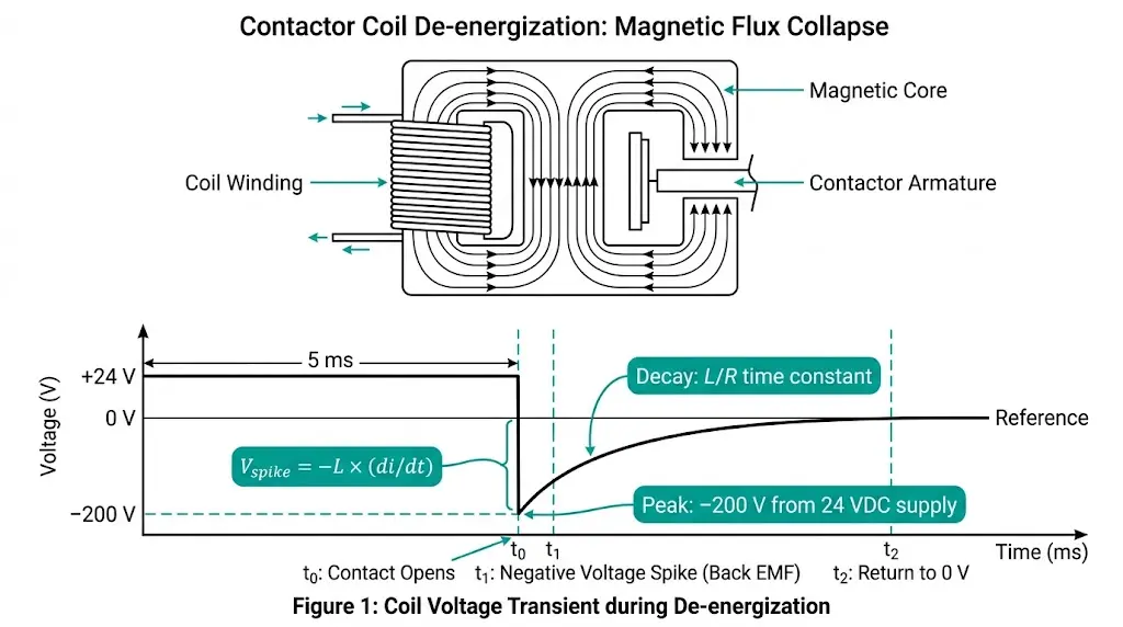
When current through an electromagnetic coil suddenly interrupts, the collapsing magnetic field induces a voltage spike that can exceed 10–20 times the supply voltage. This back-EMF phenomenon follows a fundamental electromagnetic relationship:
Vspike = −L × (di/dt)
Where L represents coil inductance (typically 0.1–2 H for industrial relays) and di/dt is the rate of current change during contact opening. When a mechanical contact separates in 1–3 ms, the di/dt value becomes extremely large—producing transients that destroy semiconductors and erode contacts.
Consider a typical 24 VDC contactor coil with 2 H inductance carrying 100 mA. During a 1 ms interruption, the induced spike reaches approximately 200 V—more than eight times the supply voltage. Larger industrial coils routinely generate spikes of 500–1,500 V without suppression.
These transients cause three primary failure modes:
In mining conveyor control systems, unsuppressed coil transients have triggered false sensor readings up to 15 meters from the source relay. The comparison between MOV, RC, and diode methods centers on how each device handles this transient energy while balancing response time against release delay.
[Expert Insight: Field Observations on Transient Damage]
Metal oxide varistors function as voltage-dependent resistors constructed from zinc oxide (ZnO) grain boundaries. Below their clamping threshold, MOVs present high impedance exceeding 1 MΩ—effectively invisible to the circuit. When transient voltage exceeds the clamping level, the MOV transitions to low impedance within nanoseconds, shunting surge energy away from sensitive components.
Key MOV characteristics:
For a 24 VDC coil application, select an MOV with clamping voltage of 39–47 V (1.6–2× supply). The MOV remains inactive during normal operation but clamps transients to safe levels during de-energization. This minimal intervention produces negligible effect on coil release timing—typically adding less than 2 ms delay.
The primary limitation involves degradation. Each surge absorption event slightly damages the ZnO grain structure, gradually increasing leakage current and shifting clamping characteristics. High-cycle applications exceeding 100,000 annual operations may require periodic MOV replacement or oversized ratings to extend service life.
MOV devices suit applications requiring fast dropout response where some residual transient (clamped to 1.5–2× supply) remains acceptable. Safety interlock circuits and emergency stop relays benefit from MOV protection due to minimal timing impact.
RC snubber circuits combine a resistor and capacitor in series across the coil terminals. The capacitor absorbs initial transient energy while the resistor dampens oscillations and limits discharge current. This combination provides effective arc quenching particularly suited to AC coil applications.
Typical RC component values for contactor coils:
The RC time constant determines suppression characteristics. For critical damping, calculate R = √(L/C) where L represents coil inductance. Practical applications often use empirical starting values of 100 Ω paired with 0.1 μF, then adjust based on oscilloscope measurements of actual transient behavior.
RC networks offer unlimited cycle life since passive components don’t degrade from surge absorption. They also provide superior EMI reduction compared to MOVs—the capacitor slows voltage rise rate (dV/dt), reducing high-frequency emissions that couple into adjacent wiring.
The trade-off involves release timing and continuous power dissipation. On AC circuits, the capacitor charges and discharges each half-cycle, drawing continuous leakage current (typically 5–15 mA at 230 VAC). On DC circuits, the capacitor maintains coil voltage momentarily after the control switch opens, extending release time by 5–15 ms depending on component values.
RC snubbers excel in applications where cycle life and EMI performance outweigh timing sensitivity. Motor starter auxiliary contacts and indicator relay circuits commonly use RC protection.
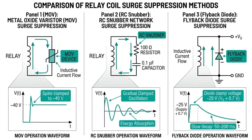
Freewheeling diodes create a closed current path for the collapsing magnetic field energy, allowing coil current to circulate and decay naturally through the winding resistance. When the control switch opens, stored magnetic energy converts to circulating current rather than voltage spike—the diode clamps transient voltage to approximately 0.7 V above supply (forward diode drop).
Diode selection requirements:
This method provides the most complete transient suppression available—virtually eliminating voltage spikes that damage semiconductors. A 24 VDC coil protected by a freewheeling diode produces a transient of only 24.7 V during de-energization versus 200+ V unprotected.
The critical limitation involves release timing. With the diode conducting, coil current decays according to the L/R time constant of the winding itself—typically 50–200 ms for industrial contactors. This represents a 3–10× increase over unprotected release time.
According to IEC 60947-5-1 governing control circuit devices, extended release times from diode suppression may violate safety interlock timing requirements. Emergency stop circuits and machine safety applications per IEC 60204-1 typically cannot tolerate release delays exceeding 10–15 ms.
Absolute restriction: Freewheeling diodes cannot function on AC circuits. During each negative half-cycle, the diode becomes forward-biased, creating a short circuit that causes immediate diode failure and potential coil damage. This misapplication accounts for approximately 15% of suppressor failures encountered during field troubleshooting.
Diode suppression suits DC control circuits where release timing is non-critical—auxiliary indication relays, status outputs, and non-safety sequencing applications.
[Expert Insight: Diode Suppression Timing Impact]
The fundamental selection decision requires matching suppressor characteristics to circuit requirements. This comparison matrix consolidates performance parameters for direct evaluation:
| Parameter | MOV | RC Snubber | Freewheeling Diode |
|---|---|---|---|
| AC circuit compatible | Yes | Yes | No |
| DC circuit compatible | Yes | Yes (with timing impact) | Yes |
| Transient clamping voltage | 1.5–2× supply | Gradual reduction | ~1 V above supply |
| Response time | <25 ns | 1–10 µs | <1 µs |
| Release time impact | Minimal (<2 ms) | Moderate (5–15 ms) | Significant (50–200 ms) |
| Cycle life | Limited (degrades) | Unlimited | Unlimited |
| EMI suppression | Good | Excellent | Good |
| Typical cost | Low | Medium | Lowest |
| Physical size | Small (12×15 mm disc) | Larger (25×35 mm module) | Small |
Selection by application type:
| Application | AC Circuit | DC Circuit |
|---|---|---|
| Safety interlocks / E-stop | MOV | MOV or TVS diode |
| Motor starter auxiliaries | RC snubber | RC snubber |
| Indicator / status relays | RC snubber | Freewheeling diode |
| High-cycle (>100k/year) | RC snubber | Diode with zener |
| PLC output protection | MOV | MOV |
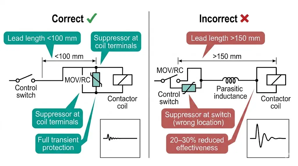
Proper installation determines whether surge suppression actually protects the circuit or merely occupies panel space. Lead length between suppressor and coil terminals represents the most critical—and most frequently violated—installation parameter.
Lead length effects:
Every centimeter of wire adds parasitic inductance (approximately 10 nH/cm for typical control wiring). This inductance sits between the suppressor and the transient source, reducing protection effectiveness. Field measurements confirm that suppressor leads exceeding 150 mm reduce clamping performance by 20–30%.
Correct installation practice:
Common mistakes and consequences:
| Mistake | Consequence | Prevention |
|---|---|---|
| Suppressor at switch instead of coil | Reduced effectiveness, continued contact erosion | Always mount at coil terminals |
| Diode installed on AC circuit | Immediate diode failure, potential coil damage | Verify AC/DC before installation |
| MOV rating too close to operating voltage | Premature degradation, increased leakage | Select clamping voltage ≥1.5× nominal |
| RC capacitor undersized voltage rating | Capacitor failure under transient | Use ≥2× peak voltage rating |
| Reversed diode polarity | Short circuit, fuse operation | Verify cathode orientation |
For RC snubbers, calculate actual resistor power dissipation. In AC circuits, the capacitor charges/discharges continuously, producing heat in the resistor according to P = ½CV²f. A 0.1 µF capacitor at 230 VAC/50 Hz dissipates approximately 0.26 W—specify minimum 0.5 W resistor rating with margin for temperature rise.
Medium-voltage switching equipment presents specific surge suppression requirements due to higher coil power ratings and critical timing constraints. Control circuits for vacuum contactors and vacuum circuit breakers demand careful suppressor selection to maintain protection coordination.
Vacuum contactor applications:
Operating coils in vacuum contactors typically draw 50–200 mA at 110–230 VAC or 24–110 VDC. High-cycle applications—capacitor bank switching, motor starting duty—accumulate hundreds of thousands of operations annually. RC snubbers provide the preferred solution for AC-controlled units, offering unlimited cycle life without timing penalties.
For JCZ-series vacuum contactors in capacitor switching service, fast dropout timing prevents contact welding during bank de-energization. MOV suppression maintains release characteristics while providing adequate transient clamping.
Vacuum circuit breaker applications:
Trip coil circuits require especially careful consideration. Protection coordination depends on consistent, fast breaker operation—extended release times from improper suppression can allow fault current to persist beyond coordination limits.
Standard practice for VS1-series indoor VCB installations:
DC control circuits powered from station batteries (typically 110 VDC or 220 VDC) commonly use zener-diode combinations. The zener increases clamping voltage above a simple freewheeling diode, accelerating current decay while still preventing damaging transients from reaching solid-state control modules.
Proper coil surge suppression represents one element of reliable switchgear control system design. XBRELE supplies vacuum circuit breakers and vacuum contactors with factory-engineered control circuits incorporating correctly specified protection components.
Our technical team provides:
For medium-voltage switching equipment with properly protected control circuits, contact XBRELE’s engineering team for specification support on new installations or existing system upgrades.
What happens if I install a flyback diode on an AC coil?
The diode conducts during each negative half-cycle, creating a short circuit path that typically destroys the diode within seconds and may damage the coil winding. AC circuits require bidirectional suppression—use MOV or RC snubber networks instead.
How do I determine if my existing MOV suppressor needs replacement?
Measure leakage current at nominal voltage; values exceeding manufacturer specifications (typically >1 mA at rated voltage) indicate degradation. Alternatively, compare clamping voltage during a controlled test transient against original specifications—increases beyond 10% suggest replacement.
Can I combine multiple suppression methods for better protection?
Yes, but with careful consideration. MOV plus RC combinations provide both fast clamping and dV/dt reduction. However, parallel diodes with MOVs on DC circuits can create interaction issues—the diode conducts first, potentially leaving the MOV unexercised and subject to degradation from other system transients.
Why does my relay still arc despite having surge suppression installed?
Common causes include excessive lead length (suppressor mounted away from coil), degraded MOV no longer clamping effectively, or suppressor rating mismatched to actual coil voltage. Verify mounting location first—field experience shows lead inductance causes more suppressor failures than component defects.
Do solid-state relay outputs require coil suppression even without mechanical contacts?
Yes. Solid-state outputs eliminate contact arcing but remain vulnerable to back-EMF damage. Transistor outputs typically withstand 30–50 V maximum; a 24 VDC coil can generate 200–400 V spikes. Suppression protects the semiconductor junction regardless of switching technology.
What suppressor type provides the longest service life in high-cycle applications?
RC snubber networks and freewheeling diodes offer unlimited cycle life since passive components don’t degrade from repetitive surge absorption. MOVs degrade with cumulative energy absorption—applications exceeding 100,000 annual operations benefit from oversized MOV ratings or alternative suppression methods.
How does ambient temperature affect suppressor selection?
MOV leakage current increases approximately 0.5% per °C above 25°C, affecting both performance and aging rate. Electrolytic capacitors in some RC assemblies lose capacitance below −20°C and age rapidly above 70°C. Film capacitor RC networks and silicon diodes maintain stable performance across −40°C to +85°C industrial ranges.